


Servicios Personalizados
Revista
Articulo
 Inglés (pdf)
  Artículo en XML
 Referencias del artículo
 Enviar artículo por email
Indicadores
 Citado por SciELO
 Accesos
Links relacionados
 Similares en SciELO
Compartir

 Permalink
Ingeniería mecánica, tecnología y desarrollo
versión impresa ISSN 1665-7381
Ingenier. mecáni. tecnolog. desarroll vol.3 no.6 México mar. 2011
Artículos
Laminar Horseshoe Vortices Upstream of a Short Cylinder Normal to a Flat Plate
Rodríguez y Domínguez Marcos Matthaeus*1, Romero-Méndez Ricardo*1 De Lange Dirk Frederik*1 and Hernández-Guerrero Abel*2
*1School of Engineering, Universidad Autónoma de San Luis Potosí, San Luis Potosí, 78290, México.
*2Department of Mechanical Engineering, Universidad de Guanajuato, Salamanca, Guanajuato, 36730, México.
Fecha de recepción: 11-01-2011
Fecha de aceptación: 25-02-2011
Abstract
A flow visualization experiment was performed in order to characterize the laminar horseshoe vortex system that appears upstream of the ¡unction of a short cylinder and a single flat plate parallel to the flow direction. The experiments were performed in a water tunnel and the technique used for flow visualization was laser illumination of seeded particles whose traces were captured using long exposure photograph. Geometrical and flow parameters, such as Reynolds number and height-to-diameter ratio of the cylinders, are varied during the experiments and the appearance of the flow regimes is determined as a function of these parameters. The behavior of vortex systems is analyzed. Additional to the types of horseshoe vortex systems reported in investigations with tall cylinders, a chaotic type of vortex system was observed for this case. This chaotic horseshoe vortex system occurs only in short cylinders and for sufficiently high Reynolds numbers. Information about the frequency of appearance of periodic vortex systems is presented, from which we could define a cylinder height beyond which the flow behavior becomes independent of height. Information of the position of the main vortex closer to the cylinder and the position of the stagnation point over the cylinder is also reported.
Keywords: Horseshoe vortex, short cylinder, separation effect, chaotic vortex system, periodic behavior.
Resumen
Este artículo reporta experimentos de visualización realizados para caracterizar el vórtice de herradura que se presenta aguas arriba de la zona de unión de un cilindro corto colocado normal a una placa plana paralela al flujo. Los experimentos fueron realizados en un túnel de agua y el método de visualización empleado es la iluminación por láser de partículas micrométricas; las imágenes de este flujo fueron capturadas por medio de fotografías de exposición prolongada. En este estudio los parámetros geométricos y de flujo, tales como el número de Reynolds y la razón de altura a diámetro de los cilindros se varían, y la aparición de los regímenes de flujo se determina como función de estos parámetros, siendo analizado el comportamiento del sistema de vórtices que aparece. A diferencia de los resultados encontrados en el caso de cilindros altos, en el caso de cilindros cortos se encontró un sistema caótico de vórtices, el cual aparece en el caso de cilindros muy cortos y a números de Reynolds suficientemente grandes. También se presenta información acerca de la frecuencia de aparición de vórtices en el caso de sistemas de vórtices periódicos y acerca de la posición del vórtice principal más cercano al cilindro y del punto de estancamiento. A partir de estos resultados se puede encontrar la altura del cilindro a partir de la cual el sistema de vórtices se vuelve independiente de la altura del cilindro.
Palabras Clave: Vórtice de herradura, cilindro corto, efecto de la separación, sistema de vórtices caóticos, comportamiento periódico.
Introduction
The junction of a straight cylinder and a flat plate parallel to a flow is a very common configuration in many situations, such as in the vertical supports of a bridge that are seated on a riverbed, the intersection of tubes and plates in a heat exchanger or the base of buildings. The horseshoe vortex that is formed at the intersection of a protruding object and a flat plate is responsible of the erosion that occurs near the base of vertical supports of bridges, as well as of the increase in heat transfer coefficient in the intersection of a tube and a plate in a heat exchanger; the characterization of the horseshoe vortex system is important for the design and improvement of some engineering devices such as those mentioned before. An interesting feature of horseshoe vortex systems is that as the parameters, such as Reynolds number and geometrical parameters change, the flow takes on different and unusual forms.
Several researchers have described vortex systems under several situations. Schwind (1962) made experiments upstream of a wedge located on top of a flat plate, finding different systems of horseshoe vortices depending on the fluid velocity. These regimes included a separation of the boundary layer without observable vortex structures for the lower velocities, while for a little increase of velocity a single clockwise rotating vortex was seen. As the flow velocity was increased further, the number of vortices increased, and an oscillatory vortex system was evident, and merging of vortices was seen. Norman (1972) studied the flow around cylinders and short obstacles by means of smoke visualization; he examined the vortices upstream of the obstacle and proposed models for description of the flow patterns. For a particular case of Reynolds number the core of the horseshoe vortex was almost stationary, located upstream of the cylinder. He also observed an oscillatory behavior of the horseshoe vortex system, starting at almost constant values of Reynolds number based on the size of the obstacle. Baker (1979) studied experimentally the horseshoe vortex that is formed around the base of a cylinder by a laminar boundary layer that has separated. He used a wind tunnel and smoke visualization, observed vortex oscillations and took velocity measurements. He encountered different flow patterns depending upon the flow speed and cylinder size with more vortices appearing as the flow velocity was increased. Above a certain velocity, the entire horseshoe vortex system became oscillatory in a regular manner. At still higher velocities the flow became unsteady and turbulent. In a more recent paper, Baker (1991) studied the oscillation of laminar horseshoe vortex systems, classifying them into two types: (a) oscillations due to an oscillation of the entire separated flow system upstream of the cylinder and (b) horseshoe vortex oscillations due to an oscillation of the vortex core of the primary vortex. These hypotheses were used to identify how the frequency of oscillation varied and to what parameters this frequency was sensitive. The author found that oscillations of type (b) were first observed and these oscillations triggered the stronger oscillations of type (a).
A paper by Simpson (2001) provides a review of the investigations that have studied juncture flows, both over streamlined and blunt bodies. He reviews the computational methods used to capture the flow features of horseshoe vortex systems. This author also reviews some work on the control, modification, or elimination of such vortices.
Several investigations have recently analyzed the flow around short blunt bodies protruding from a flat plate: Thomas (1985) was the first to point out the possible effect of height-to-width ratio on the nature of the horseshoe vortex system, Seal et al. (1995) studied the vortex system at a rectangular block-flat plate juncture. Tsutsui et al. (2000) performed an experimental study of the flow and heat transfer around a cylindrical protuberance with a height to diameter ratio of 0.35 mounted on a flat plate, having determined the local drag coefficient and heat transfer around the protuberance. In a second paper Tsutsui and Kawahara (2006) studied the heat transfer characteristics of a low aspect ratio cylindrical protuberance immersed in a turbulent boundary layer, Pattenden et al. (2005) studied the turbulent flow over a unit aspect ratio circular cylinder mounted on a flat plate by using PIV and surface pressure measurements, Lin et al. (2002) conducted an experimental investigation of horseshoe vortex flows near the juncture of a vertical plate and a base plate, the Reynolds number was varied in the range 400 to 1000 and the height-to-width ratios from 0.5 to 4.0. For the flow conditions of their experiments, they recognized four major categories defined as (a) steady vortex system, (b) periodic oscillation vortex system with small displacement, (c) periodic breakaway vortex system, and (d) turbulent-like vortex system. Lin et al. (2003) presented a simultaneous PIV and LDV experimental investigation of periodic horseshoe vortex system near the juncture of a plate and a square cylinder, finding the same vortex system classifications described by Lin et al. (2002), identifying the turbulent-like vortex systems as chaotic. Recently, some researchers have continued experimental investigations of horseshoe vortex systems: Wei et al. (2008) have focused their interest on the effect that the section shapes of the cylinders have on the nature of the horseshoe vortex system. Wang et al. (2009) have introduced rods upstream of the cylinder to suppress the appearance of horseshoe vortices.
From the previous literature review, it is noticeable that the case of laminar vortex systems near the juncture of a short cylinder mounted on a flat plate requires to be further studied, since it may be of interest in applications such as design of extended surfaces used in heat exchangers. For this reason the present study concentrates in the analysis of this flow situation. This investigation employs qualitative information obtained by a non-intrusive technique such as seeding of neutrally buoyant particles in order to obtain a picture of the instantaneous velocity field of the domain of interest.
Experimental Apparatus and Method
Test Conditions and Flow Visualization Technique
Qualitative flow visualizations and measurements were performed for the flow occurring upstream of a short cylinder mounted normal to a flat plate. The experiments were performed using a horizontal flow visualization water tunnel which has a test section constructed of tempered glass windows to permit the maximum viewing of the model. The test section of the water tunnel is 0.381 m high, 0.508 m wide and 1.5 m long. The flow stability at the entrance of the test section is achieved using several flow conditioning elements. The contraction section of the water tunnel has an area ratio of 6:1; this geometry provides good velocity distribution, turbulence reduction, and avoidance of local separation and vorticity development. The range of velocities that is possible goes from 0.02 to 0.3 m/s, and a particular velocity within this range can be selected by varying the pump rotational speed by means of a variable-frequency drive.
Figure 1 shows a schematic of the experimental model and light disposition used in the experiments. In Figure 1 the fluid moves from left to right. The model was suspended inside the test section by attaching it to the frame of the water tunnel. A Nylamid cylinder of constant diameter (D=0.05 m) was mounted normal to a transparent acrylic flat plate (0.35 m wide, 1.2 m long and 3 mm thick) at several distances from the leading edge of the plate. In order to reduce perturbations that could affect the development of the boundary layer along the plate, the leading edge of the plate was streamlined. To show the effect of the height-to-width ratio of the normal cylinders, several cylinder heights were chosen (ranging from 1 cm to 8 cm).
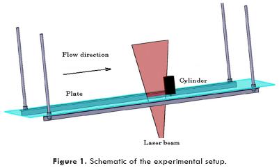
This investigation uses the seeding of reflective micrometric particles in order to visualize the flow. These particles are hollow glass spheres coated with silver to allow the best light reflection; in addition to this advantage, the particles are small enough to approximately follow the fluid paths. The visualization particles are illuminated with the light emitted from a 30 mW He-Ne laser lamp, which has been opened into a light sheet by a cylindrical lens. The laser light was cast through the bottom of the water tunnel to illuminate a fan-shaped plane that serves to keep track of the two-dimensional motion of seeded particles on a symmetry vertical plane ahead of the cylinder. The room where the experiments took place was completely darkened in order to avoid the presence of any light source other than the laser light sheet.
A reflex photographic camera with a 50 mm f/2.5 compact macro lens and a black and white photographic film was used to capture the streaks traced by the suspended particles. Exposure times of 1/15 and 1 /8 of a second are chosen as the right times for the illumination and velocity conditions of the experiment. Extended developing times were used in order to sensitize the negative to the presence of very dim light. The images presented in this paper were digitized after printing the photographs taken during the experiments. Direct observation of the vortex system is also made with the help of video recordings that were later analyzed in detail.
Experimental Conditions
The cylinder diameter, D, was used as the characteristic length for defining the relevant nondimensional parameters for this study. Other geometric dimensions of importance are the cylinder height, h, and the distance from leading edge of the plate to cylinder center, l. The important flow parameter is the velocity, V. Having defined the characteristic length, the velocities to be tested, and the dimensions of the different cylinders tested, the nondimensional parameters for the experiments are the following: height-to-diameter ratio, H=h/D, ranging from 0.2 to 1.6, ratio distance from tube center to leading edge of plate to diameter, L=l/D, from 5 to 20, tube diameter based Reynolds number, Re=VD/n (where n is the kinematic viscosity of the fluid), ranging from 1400 to 5000.
The experiments were conducted by fixing the position of a cylinder of a given diameter and height and increasing the speed within the established range of Reynolds number values. We started with the shortest cylinder (H=0.2) and proceeded with taller cylinders with increases of height until we ended up with the tallest cylinder (H=1.6). We studied the effect that Reynolds number, cylinder height and distance from leading edge of plate have on the nature of the vortex system upstream of the cylinder. Although in most cases used a value L=15, we also explored the effect of the distance from the leading edge of the plate. Frequency response of vortex systems was expressed in terms of Strouhal numbers, St=ωD/V, where ω is the frequency of appearance of vortices.
The frequency of appearance of vortices was determined from the time needed to see 20 vortices disappear, then averaging the period of disappearance of each vortex. It is easier to see vortices disappear, because it always occurs in the same position for a given flow condition. The time was measured by a chronometer. As an example, in a typical case, it takes about a minute to count 20 vortices disappear. Considering an uncertainty of 1 /2 of a second in the pushing of the stop button of the chronometer, then the uncertainty in the measurement of the period is 0.83%, not very different to the uncertainty in the measurement of frequency.
The position of the vortices center of rotation and stagnation point of the vortex system was determined by measuring directly in printed photographs with the help of a digital caliper. The combined standard uncertainty of this measurement of vortex center positions and stagnation point was estimated to be 3.78%.
A detailed description of the results will be given in the next section.
Results
Experimental validation
The results were validated by repeating part of the experiments performed by Baker (1979). An experiment especially used for validation was that of a single cylinder mounted over a flat plate. To this end, a cylinder with H=0.5 was located at different positions from the leading edge expressed by the cylinder diameter-to-thickness ratio of the boundary layer at that position, D/t, where t is the boundary layer thickness (δ99%) determined according to the Blasius definition, and the nature of the vortex system was observed. Four different cases were observed within the range tested: steady systems with two, four and six vortices, and unsteady vortex systems. Figure 2 shows a comparison of the results of this validation experiment and the map of behavior reported by Baker (1979). Very good agreement is observed between our experiment and that of Baker (1979).
Flow visualization
Five different flow patterns were observed, and the appearance of these flow patterns depended on the Reynolds number and ratios H=h/D and L=l/D. The vortex systems that were identified are: (i) steady, (ii) oscillatory, (iii) amalgamating, (iv) breakaway and (v) chaotic vortex systems. In some cases the transition from one system to the subsequent system was observed. Figure 3 shows the ranges of appearance of these vortex systems for L=15. The general tendency is to have steady systems for small heights of cylinder and low Reynolds numbers. Comparing these results with those for tall cylinders, presented by Pérez-Gutiérrez et al. (2006), the possibility that the flow has to evade the obstacle when this is short, stabilizes the flow when Re is small, but also may produce a chaotic behavior for moderately high Reynolds numbers. As reported by Rodríguez et al. (2006), chaotic systems are not present when the cylinder is confined between two plates, and so the interaction of the vortex with the main flow on top of the cylinder may have a destabilizing effect on the vortex system. There is a thin belt of oscillatory systems that occur for slightly larger Reynolds numbers and heights than those encountered when the flow is steady. Chaotic systems appear for large Re and H ≤ 0.8. When H= 1 or when the cylinder is taller than its height chaotic systems no longer appear, and for that case the next system that appears as Re is increased is the amalgamating vortex system, which later gives way to breakaway vortex systems.
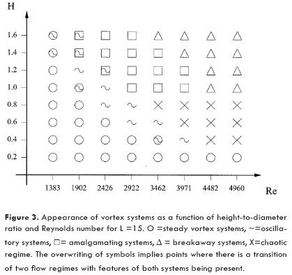
By approaching the cylinder to the leading edge of the plate, for instance L = 5, there is a predominance of steady vortex systems, and disappearance of chaotic systems. In the case L=20, chaotic systems appear at even smaller Reynolds numbers. For all cases tested, chaotic systems are restricted to cylinders that are shorter than its diameter.
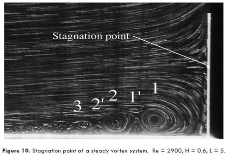
Steady systems appear at smaller Re and H. These systems are characterized by one or more vortices, each of which has a fixed center of rotation. There are main vortices, which start with the vortex nearest to the cylinder, that rotate in a clockwise sense (or whose upper tangential velocity component is in the same direction as the main flow), and secondary vortices that rotate in the opposite sense, which are formed between two main vortices or after a main vortex. In the photographs presented in this investigation main vortices are identified with plain numbers, with vortex 1 being the closest to the cylinder; secondary vortices with primed numbers and the same numbering convention is used.
The simpler steady vortex systems evidence a single vortex 1 and, in some cases, an accompanying vortex 1', the more complex steady vortex systems have at least six vortices. The cylinder height is determinant for the appearance of vortices, for instance cylinders with H = 0.2 do not allow the appearance of long chains of vortices, but for cylinders where H equals or is larger than 0.4 steady systems grow in number of vortices as Re is increased; for a fixed Re, the number of vortices grows as the height of the cylinder is increased. Figure 4 shows how for Re=2900 and H=0.2 (Figure 4 a)) is appreciable the presence of two main vortices, but for taller cylinders (Figures 4 b) and c)) the number of observable main vortices increases to 3, where it stays even if the cylinder is taller. It is important to see in the sequence a) to c) the position of the cores of the vortices is displaced away from the cylinder as the cylinder height is increased.
Oscillatory systems are periodic vortex systems that show slight spatial oscillation of the vortex cores accompanied by periodic decrease and growth of the size of the vortices according to the approaching or moving apart of adjacent main vortices, which may move in opposite directions. In general, vortex 2 approaches or moves away from vortex 1, giving way to the decrease or increase in size of vortex 1'. The intensity of vortex 2 may produce i) a slight oscillation of vortex 1, which is the behavior that presents immediately after the system loses its steadiness due to increases of Re or H, ii) collisions with vortex 1, where vortex 2 may disappear, or iii) a behavior that is similar to that of amalgamating vortex systems, where vortex 2 tries to swallow vortex 1, but since this is still too big, vortex 2 disintegrates and is replaced by a new vortex 2 that is born in the same place where it used to be the old vortex 2.
In the sequence of Figure 5a)-b) the behavior of an oscillatory vortex system is shown. Vortex 1 shrinks considerably from 5a) to 5b) but keeps an almost fixed core position, while in 5b) vortex 2 has come the closer to the cylinder, competing with and weakening vortex 1. It is important to mention that, in our observations, oscillatory systems always were formed by at least three main vortices.
Amalgamating vortex systems are periodic systems where the vortices first appear in the boundary layer separation region with a very elliptic shape, and acquire a circular shape as they get closer to the cylinder. The lifecycle of amalgamating vortices is as follows: they first grow while moving toward the cylinder, reaching a peak in size, after which they shrink while moving further towards the cylinder, when they reach their nearest point to the cylinder, start a back motion in which they reduce their size considerably, finally they are swallowed by vortex 2 that was born after vortex 1. For a given H, as the Reynolds number is increased, the vortex gets closer to the cylinder and becomes smaller and the back motion is shorter.
Figure 6 shows the evolution and lifecycle of an amalgamating vortex identified with an asterisk, from its birth to the moment it is swallowed by the vortex that was born the next cycle. In this sequence of photographs the progress in time corresponds to 1/8 of the life period of a vortex. It is noticeable that the back motion of the vortex is faster that the downstream motion of the vortex. It is also worth mentioning that the secondary vortex that appears between two steady or unsteady main vortices has disappeared for this case. This particular vortex system is practically on the verge of becoming of another vortex system: the breakaway vortex system; this can be asserted from the short back motion of the vortex and its considerable reduction in size.
When the back motion of vortex 1 is reduced to zero distance and the vortex dies by itself in the position closer to the cylinder instead of being swallowed by the incoming vortex, the vortex system is considered as a breakaway vortex system. The way the vortices are born is similar to what happens in amalgamating vortex systems.
Flow structures without an identifiable pattern were observed in the chaotic regime. Turbulent-like chaotic vortices were observed previously by Lin et al. (2002). The lifetime of the vortices that appear in a random fashion is short, the system is very unstable, and there was not identified any behavior that could give a qualitative indication of periodicity related to Re or H. Figure 7 shows photographs corresponding to a chaotic vortex system, all of the photographs taken for the same flow and geometric parameters but at different moments.
Periodic Behavior of Vortex Systems
Oscillatory, amalgamating and breakaway vortices are periodic systems with varying frequency of appearance of vortices. As shown in Figure 8, around Re =2900 their periodic behavior becomes independent of the cylinder height. As seen in Figure 3, for H=0.6 and H=0.8 chaotic systems begin immediately after oscillatory systems, and that is why the lines for those cases are truncated in Figure 8.
Given the similitude of the curves of cases H= 1.4 and H= 1.6, it is considered that for L=15, the vortex system periodic behavior becomes independent of the cylinder height when H ≥ 1.4.
Position of vortex 1.
Figure 9 indicates the position of the core of vortex 1 as a function of Re and H for L=15. It is seen that for short cylinders, 0.2≤H≤0.6, the position of the vortex respect to the cylinder is almost constant. As the height is increased, 0.8≤H ≤2.0, the main vortex distance to the cylinder decreases gradually with Re. One of the factors that may be causing this effect is the decrease in boundary layer thickness as the Reynolds is increased. It is also observed that for cylinders where H>0.8, the vortex gets closer to the cylinder as the height is increased up to H= 1.4, but for sufficiently tall cylinders, H ≥ 1.4, the position of the vortex becomes independent of the height.
Position of stagnation point.
A stagnation point that marks the boundary that splits the incoming fluid in two - the fluid that forms the horseshoe vortex system and the remaining fluid - was found for all cases. Figure 10 illustrates how this stagnation point presents in the flow. It is important to mention that the position of the stagnation point for a given set of parameters (Re, H and L) remains fixed; this is true even for the cases of unsteady, amalgamating, breakaway or chaotic vortex systems, where the position of the vortex cores is time dependent. Figure 11 shows the variation of the position of the stagnation point as a function of Re and H for a fixed value L=15. It can be seen that as Re is increased there is a monotonic decrease of the distance from the plate at which the stagnation point appears. It can also be seen that, for a fixed Re, the distance at which the stagnation point occurs grows monotonically for growing H, but stabilizes when H ≈ 1.4.
Conclusion
For the configuration studied in this paper, the height-to-diameter ratio as well as flow conditions have an important effect on the behavior of vortex systems. Five different flow regimes were observed in the experiments: steady, oscillatory, amalgamating, breakaway and chaotic vortex systems, although combinations of some of these were also observed in the parametric border region of some systems. Unlike the flow behavior of horseshoe vortices near sufficiently tall cylinders, the possibility that the flow has to evade the obstacle when this is short stabilizes the flow when Re is small, but also may produce a chaotic behavior for moderately high Reynolds numbers, caused by interaction of the main flow and the vortex system. The chaotic behavior of horseshoe vortices, reported previously by Lin et al. (2002), appears only when the cylinder height is a little less than its diameter when L=15; in this flow behavior flow structures without an identifiable pattern are observed, the lifetime of the vortices, that appear in a random fashion, is short, the system is very unstable, and it is not possible to identify a tendency that could give a qualitative indication of periodicity related to Re or H. The frequency of appearance of periodic vortices was also studied, finding that the Strouhal number becomes independent of the cylinder height for sufficiently tall cylinders (in this case H≥ 1.4 when L= 15). Additionally, the position of the main vortex 1 core also becomes independent of height for sufficiently tall cylinders. The position of the stagnation point on the cylinder presents a monotonic growth but seems to become independent of H for sufficiently tall cylinders.
Acknowledgments
The authors would like to acknowledge the support of the Mexican National Council for Science and Technology (CONACYT), under grant 84618. The authors also thank Mr. Manuel Lozano for his help and advice during the course of the experimental investigation.
References
Baker C.J., "The laminar horseshoe vortex", Journal of Fluid Mechanics, 95, 347-367, 1979. [ Links ]
Baker C.J., "The oscillation of horseshoe vortex systems", Journal of Fluids Engineering, 113, 489-495, 1991. [ Links ]
Rodríguez y Domínguez, M., Romero-Mendez R., Ramos-Palau M., Perez-Gutierrez F.G., "The laminar horseshoe vortex upstream of a short-cylinder confined in a channel formed by a pair of parallel plates", Journal of Visualization, 9, 309-318, 2006. [ Links ]
Lin C., Chiu P. H., Shieh S.J., "Characteristics of horseshoe vortex system near a vertical plate-base plate juncture", Experimental Thermal and Fluid Science, 27, 25-46, 2002. [ Links ]
Lin C., Lai W. J., Chang K.A., "Simultaneous particle image velocimetry and laser Doppler velocimetry measurements of periodical oscillatory horseshoe vortex system near square cylinder-base plate juncture", Journal of Engineering Mechanics-ASCE, 129, 1173-1188, 2003. [ Links ]
Norman R.S., "On obstacle generated secondary flows in laminar boundary layers and transition to turbulence", Ph.D. Dissertation, Illinois Institute of Technology, 1972. [ Links ]
Pattenden R. J., Turnock S. R., Zhang X., "Measurements of the flow over a low-aspect ratio cylinder mounted on a ground plane", Experiments in Fluids, 39, 10-21, 2005. [ Links ]
Pérez-Gutiérrez F.G., Romero-Mendez R., Dominguez M.M.R., Ramos-Palau M., Cardenas-Galindo A., "Flow visualization of the flow near the junction of a long cylinder and a flat plate", Ingeniería Hidráulica en México, 21, 105-113, 2006 (in Spanish). [ Links ]
Schwind R., "The three dimensional boundary layer near a strut", Technical report, Gas Turbine Laboratory, MIT, 1962. [ Links ]
Seal C.V., Smith C.R., Akin O. and Rockwell D., "Quantitative characteristics of a laminar unsteady necklace vortex system at a rectangular block-flat plate juncture", Journal of Fluid Mechanics, 286, 117-135, 1995. [ Links ]
Simpson R.L., "Junction flows", Annual Review of Fluid Mechanics, 33, 415-443, 2001. [ Links ]
Thomas S.W., "The unsteady characteristics of laminar juncture flow", Physics of Fluids, 30, 283-285, 1987. [ Links ]
Tsutsui T., Igarashi T., Nakamura H., "Fluid flow and heat transfer around a cylindrical protuberance mounted on a flat plate boundary layer", JSME International Journal, Journal Series B-Fluids and Thermal Engineering, 43, 279-287, 2000. [ Links ]
Tsutsui T., Kawahara M., "Heat transfer around a cylindrical protuberance mounted in a plane turbulent boundary layer", Journal of Heat Transfer-Transactions of the ASME, 128, 153-161, 2006. [ Links ]
Wang, J.M., Bi, W.T., Wei Q.D., "Effects of an upstream inclined rod on the circular cylinder-flat plate ¡unction flow", Experiments in Fluids, 46, 1093-1104, 2009. [ Links ]
Wei Q.D., Wang J.M., Chen G., Lu Z.B., Bi W.T., "Modification of ¡unction flows by altering the section shapes of the cylinders", Journal of Visualization, 11, 115-124, 2008. [ Links ]

