 , grouped in a six-dimensional array 1:
On the Nature of the Cartesian Stiffness Matrix
Jorge Angeles
Department of Mechanical Engineering & Centre for Intelligent Machines McGill University. angeles@cim.mcgill.ca
Fecha de recepción: 25-03-10 ]]> Fecha de aceptación: 28-04-10
Abstract
The 6x6 stiffness matrix pertaining to a rigid body mounted on a linearly elastic suspension is revisited here, with the aim of shedding light on its nature via its associated eigenvalue problem. The discussion is based on screw theory and the eigenvalue problem thus arising, in its generalized form. The eigenvalues of the stiffness matrix are shown to occur in real, symmetric pairs, something that has been somehow overlooked in the literature, the product of each eigenvalue by the pitch of its corresponding eigenvector being shown to be non-negative.
Key words: Screw theory, stiffness matrix, multibody systems, eigenscrews, eigenpitches.
Resumen
En este artículo se revisa la matriz de rigidez, de 6 x 6, asociada a un cuerpo rígido montado sobre una suspensión linealmente elástica, con el objeto de aclarar sus propiedades intrínsecas. Para este fin, se recurre a la teoría de torsores y a la forma generalizada del problema de autovalores de esta matriz. Se demuestra que los autovalores aparecen en pares reales y simétricos, y que el producto de cada autovalor por su paso de torsor correspondiente es no-negativo.
Palabras clave: Teoría de torsores, matriz de rigidez, sistemas poliarticulados, torsores propios, pasos (de torsor) propios.
]]> Introduction
The subject of the paper is the Cartesian stiffness matrix in multibody system dynamics, i.e., the 6 x 6 stiffness matrix pertaining to a rigid body mounted on a linearly elastic suspension. This matrix is becoming increasingly important in the design of modern mechanical systems, such as compliant mechanisms, microelectromechanical systems (MEMS) and extremely fast robots. In these systems one body is much stiffer than its counterparts that couple it to a rigid base. In this case, the mathematical model of the system can be formulated under the assumption that the body in question is rigid, while the flexible bodies are massless. Furthermore, in an elastostatic analysis of the system, one can make abstraction of the mass of the rigid body and focus on the elastic behavior of the suspension. In general, the rigid body is free to undergo six-degree-of-freedom motion with respect to the base. Because of the elastic suspension, every displacement of the body entails a wrench—a force and a concomitant moment. Moreover, the rigid-body displacement can be modelled as a "small-amplitude" displacement screw (SADS). Under these conditions, the potential energy of the system a) is entirely stored in the suspension and b) becomes a quadratic form in the SADS. If the pose—position and orientation—of the rigid body is defined from that at which the potential energy of the suspension is zero, then the components of the SADS can be regarded as the generalized coordinates of the mechanical system—body plus suspension—at hand. The Hessian matrix of the potential energy with respect to the foregoing generalized coordinates is defined as the system Cartesian stiffness matrix, represented by K. Since the potential energy cannot be negative, K is a symmetric, positive-semidefinite or positive-definite matrix.
Research has been reported on both the analysis and the synthesis of the Cartesian stiffness matrix. Loncaric (1987) used the concept of generalized spring to refer to the Cartesian stiffness matrix. In the literature, the elastic suspension is more often than not modelled as a parallel array of simple translational springs (Griffis and Duffy, 1993).
The stiffness matrix is of the utmost importance in robotics, where a (scalar) performance index is sought that measures how stiff a robot composed of rigid bodies coupled by actuated elastic joints at a prescribed posture is. A plausible candidate would be a norm of the stiffness matrix. Problem is, the Cartesian stiffness matrix has entries with disparate physical units, and hence, does not admit a norm. To cope with this quandary, in connection with the inertia matrix in robotics, Kövecses and Ebrahimi (2009) proposed a decomposition of the inertia matrix that naturally leads to a change of variables in which the resulting matrix is dimensionally homogeneous. The same concept can be applied to the stiffness matrix if a norm of this matrix is needed. However, the issue of performance index lies outside the scope of this paper and is, hence, left aside.
While the Cartesian stiffness matrix has been the object of intensive research, its properties have not as yet been fully investigated. Indeed, an in-depth study of the eigenvalue problem associated with the Cartesian stiffness matrix is still missing in the literature, yet it is essential to elucidate the nature of the stiffness matrix. Because of the positive semidefiniteness of the matrix, its eigenvalues are bound to be real and non-negative, its eigenvectors mutually orthogonal; however, in the realm of screw theory, orthogonality is meaningless. As recognized by Ding and Selig (2004), the eigenvalue problem at stake is mechanically significant only if formulated in a generalized form, which leads to a natural mechanical interpretation of the eigenvalues and eigenvectors of the stiffness matrix. With this formulation, the eigenvectors of the stiffness matrix turn out to be mutually reciprocal, in the screw-theoretical sense. In the foregoing reference, Ding and Selig include a historical outline of the study of the Cartesian matrix, that goes back to Ball and von Mises. Recent studies have focused on the synthesis of a prescribed6 x 6 stiffness matrix, and its physical realization by means of unidirectional linearly elastic springes. For example, Ciblak and Lipkin (1999) proposed a method of synthesizing a linearly elastic suspension composed of simple translational springs with prescribed stiffness matrix. An important area of application of the concept is the design of compliant mechanisms, where progress has been recently reported (Kim, 2008; Su, Dorozhkin and Vance, 2009). Huang and Schimmels (1998; 2000) laid out the condition for the feasibility of a Cartesian stiffness matrix realizable by unidirectional springs. Most works in the literature limit their scope to springs of this kind. Ding and Selig (2004) went a step further, to compute the Cartesian stiffness matrix of a more general suspension, namely, a coiled spring, using a finite element model. Interestingly, the compliance matrix obtained by Ding and Selig verifies Huang and Schimmels' condition for the stiffness matrix. However, no general result along these lines has been reported.
In this paper the intention is to contribute to the understanding of the nature of the Cartesian stiffness matrix. The concepts are illustrated with a numerical example that arose from the design of microaccelerometers.
Background on Screw Theory
The pose of a rigid body is given by the position of one point of the body, termed the landmark point—usually chosen as the centre of mass of the body in dynamics—and its orientation in a given reference frame F. To simplify matters, it is customary to define a reference pose as that at which the landmark point finds itself at the origin O of F. Under these conditions, the components of the displacement screw represent the generalized coordinates of the body, and hence, of the body-suspension system.
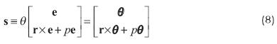
A general displacement of a rigid body, termed screw displacement, involves both a translation of its landmark point that takes the point from O to a new position ρ, of position vector p, and a rotation that takes the body to a new attitude, represented by the rotation matrix Q. Prior to introducing the screw displacement it is convenient to introduce the Plücker coordinates of a line , grouped in a six-dimensional array 1:

in which e is the unit vector denoting the direction of and μ is the moment of the line, which can be interpreted as the moment of a unit force whose line of action is , with respect to the origin O. Hence, if r denotes the position vector of a point R of , μ = r x e. However, since these six coordinates are subjected to the two quadratic constraints of eq.(1), a line is defined uniquely by four independent real numbers. It is far more convenient to work with the whole six dependent coordinates than with an independent quadruplet drawn from the given six. A unit screw  is defined as a line supplied with a pitch p
 , namely,

The pose of the body can be represented by a pair (p, Q). According to Euler's Theorem (Synge, 1960), a rigid-body rotation about a point is characterized by an axis of direction given by a unit vector e and an angle q about the axis, which passes through the foregoing point. It is known that Q takes the form (Angeles, 2007)

where 1 is the 3x3 identity matrix, while E is the cross-product matrix (CPM) of e, defined as

for any three-dimensional vector v. The reference pose of the body is, thus, given by the pair (0, 1), where 0 is the three-dimensional zero vector.
In linear elastostatics, the assumption is made that the rigid-body displacement is of "small amplitude", meaning that angle θ in Q is small, and hence, cos θ ≈ 1 and sin θ ≈ θ, the "small-angle" rotation matrix thus becoming

The unit screw given in eq.(2) is said to be represented in ray coordinates. An alternative representation, in axis coordinates, is given by

The difference between the two representations is, thus, the order in which the unit vector and the moment appear. Which representation is in use will be indicated by subscript a for axis coordinates, the absence of a subscript indicating ray coordinates. The passage from one representation to the other is given by the 6x6 permutation matrix Γ, defined in block-form as

where 1 was defined above, while O is the 3 x 3 zero matrix.
A "small"-amplitude screw displacement s is obtained upon multiplying the foregoing unit screw by a "small" amplitude θ, with the significance of an angular displacement, i.e.,
A mechanical interpretation of the unit screw is more readily understood in the realm of kinematics. Indeed, if the unit screw of eq.(2) is multiplied by an arbitrary amplitude ω with units of angular velocity, then the rigid-body twist t is obtained, namely,

are points of minimum velocity-norm, being termed, in this case, the instant-screw axis (ISA). It is noteworthy that the screw displacement and the twist are concepts pertaining to a rigid body, not to a specific point of the body. By the same token, the "small"-amplitude screw displacement s can be interpreted as composed of one upper block that represents the "small"-rotation matrix Θ, its lower block representing the "small" displacement of the point of the body that coincides with the origin O in its original pose. That is, the "small"-amplitude screw comprises information on the displacement field of the body, its lower block denoting the displacement of the point of the body located originally at the origin O. Now, given that Θ and θ are isomorphic to each other, the latter will be preferred over the former when representing a "small"-amplitude displacement. Germane to the concept of twist is that of wrench, the concurrent action of a force and a moment on a rigid body. If the unit screw of eq.(2) is multiplied by an amplitude F with units of force, then the wrench w is obtained:

with f = Fe; the wrench can alternatively be represented as

where f is the force, n the moment acting on the rigid body. Notice that both twist and wrench are given in ray coordinates. One would like to obtain the power developed by w on the body, which undergoes a twist t, by means of the inner product of the two six-dimensional arrays. A problem occurs here, however, as the product thus resulting is physically meaningless. In order to cope with this quandary, the power Π is obtained not as the inner product of the two six-dimensional arrays, but as their reciprocal product:

which rightfully produces the sum of the power developed by the moment and that developed by the force. Notice that, for the above expression to be meaningful, both the twist and the wrench must be defined at the same point.
As a consequence of the above discussion, orthogonality of screws is meaningless. Its counterpart is reciprocity: Two screws are said to be reciprocal with respect to each other if their reciprocal product vanishes.
]]> The Generalized Eigenvalue Problem in Elastostatics
Given the dimensional heterogeneity of the entries of the Cartesian stiffness matrix, it will prove convenient to partition K in four 3 x 3 blocks, namely,

where Krr is the rotational stiffness submatrix, with units of tor-sional stiffness (Nm), Ktt is the translational stiffness submatrix (N/m) and Krt is the coupling stiffness submatrix (N). Under a SADS s given to the rigid body, the suspension responds with a wrench w = Ks. Now, in trying to compute the eigenvalues and the eigenvectors of the stiffness matrix, the simple eigenvalue problem leads to inconsistent units. To solve this inconsistency, the eigenvalue problem associated with the stiffness matrix is formulated in a generalized form, namely,

where, for i = 1, . . . , 6,

with K given in eq.(13), while k is a unit screw, playing the role of a unit eigenvector of K. In block-expanded form,

whence it is apparent that the units of the eigenvalue k should be N, in order for the right-hand sides of eqs.( 16 & 17) to be consistent with their left-hand counterparts.
]]> Now we have a similar result to the symmetric eigenvalue problem:Theorem 1 The eigenvalues of K are real and the product k ip i, with ki and pi denoting the ith eigenvalue and the pitch of the ith eigenscrew, respectively, is non-negative, while the eigenvectors  are mutually reciprocal.
Proof: Multiply both sides of eq.( 14) by  from the left, to obitain twice the potential energy stored in the suspension, which is, hence, non-negative, i.e.,

Moreover, let ki be the jth eigenscrew, of eigenvalue kj ≠ ki, which thus obeys

Upon multiplying both sides of eq.( 14) by  from the left and, likewise, both sides of eq.(19) by , the two relations below are obtained:

By virtue of the symmetry of K, the two left-hand sides of the foregoing equations are identical, and hence, the right-hand sides are also, which leads to

Γki = Γki, and hence, the above equation leads to 
Because of the assumption that ki≠ kj, the foregoing equation implies that

thereby proving that every pair of eigenscrews associated with distinct eigenvalues of K is mutually reciprocal. For brevity, the ki values are henceforth termed the eigenforces, the products ki ≡ ki pi the eigenstiffnesses, and pi the eigenpitches. Repeated eigenvalues entail as many mutually reciprocal eigenscrews.
Further results are proven below that will need preliminary relations: a change of coordinates involves, in screw theory, both a change of orientation and a change of origin. The change of coordinates is given by what is known as a similarity transformation in linear algebra, namely, a change of basis for a vector space. A major difference between linear algebra and screw theory is to be highlighted: while the latter involves a change of frame, and hence, includes a change of origin, the former involves a change of basis, but no change of origin. In fact, the concept of origin does not pertain to linear algebra. Its counterpart is the zero vector, which is unique for a given vector space, regardless of the basis.
Let Q and d denote the rotation matrix and the translation that carries a frame A into a new frame B, with the axes of the latter being those of the former under a rotation Q, and the origin of B being that of A translated by vector d. Let, moreover, D = CPM(d). The matrix that transforms the components of a unit screw , as given by eq.(2), from B-coordinates into A-coordinates, henceforth represented by S, is given by (Pradeep, Yoder and Mukudan, 1989):

its inverse being


The corresponding change in axis-coordinates can be proven to be

where, in light of its definition, Γ = Γ-1 , and hence,

Under the foregoing change of frame, the stiffness matrix changes according with

which looks like a similarity transformation of linear algebra, except for Γ.
By extension of the linear-algebraic concept of similarity transformation, relations (24), (25) and (27) will be henceforth referred to as a similarity transformation—all three constitute such a transformation.
]]> When the off-diagonal block Krt of the stiffness matrix vanishes, the matrix is said to be decoupled. Decoupling, however, is not an intrinsic property, which means that it can be achieved by a similarity transformation, i.e., by a change of frame, as guaranteed by the result below:Theorem 2 The stiffness matrix can be decoupled by a similarity transformation involving only a shift of origin.
Proof: For compactness, let K'rf, K'rt and K'tt denote the blocks of [K]A, their unprimed versions those of [K]B. These are displayed below:

whence the decoupling condition, K'rt = O, follows:
QtDQKtt=-Krt
As there is no other condition to meet, Q can be freely chosen as 1, which thus leads to

whence D can be computed by inversion of Ktt. This is not a good idea because a) D must be skew-symmetric and b) Ktt can be semidefinite, and hence, singular. A solution for D that guarantees skew-symmetry relies on the concept of axial vector and the axial vector of the product of a skewsymmetric matrix by an arbitrary matrix (Angeles, 2007)1. Upon taking the axial vector of both sides of eq.(28), with krt denoting the axial vector of Krt, and recalling that D = CPM(d), one obtains


with the denominator D defined as

It is apparent from the above relations that M fails to be invertible under at least one of two conditions: a) tr(Ktt)=0 and b) Ktt is a rank-one matrix, meaning that, out of its three non-negative eigenvalues, only one is non-zero. Now, under a), M =-(1/2)Ktt, which can still be inverted if Ktt is nonsingular. If this is not the case, then eq.(29) represents less than three constraints to be obeyed by d, which means that there are one or two degrees of freedom to choose it so as to decuple K. If b), then Ktt can be expressed as  , where kt is the product of the unit eigenvector of Ktt associated with its nonzero eigenvalue times this eigenvalue. Moreover,
  , and eq.(29) becomes

The above term in parentheses can be shown to reduce to (Angeles, 2007)

which is singular, its null space being spanned by kt. To find a unique value of d, then, it is necessary to impose one more condition. If this condition is that d be of minimum Euclidean norm, then the condition is equivalent to stating that d be orthogonal to kt , i.e.,

 being needed for dimensional consistency in the ensuing calculations. Upon adjoining the foregoing equation to the first three, an "overdetermined"2 system of four equations in three unknowns is obtained, namely,
The "least-square approximation" of the foregoing system is given by the left Moore- Penrose generalized inverse of A.
However, A turns out to be isotropic3, and hence,

Therefore,

whence d, in case b), turns out to be

In summary, then, it is always possible to find a displacement of the origin of the given coordinate frame that will decouple the stiffness matrix, without any change of orientation of the frame, thereby completing the proof.
]]> One more result is now proven:Theorem 3 The eigenvalues of the stiffness matrix occur in real, symmetric pairs.
Proof: It is known from linear algebra that the characteristic polynomial of a matrix is invariant under a similarity transformation. For an arbitrary stiffness matrix, invoking Theorem 2, it is always possible to decouple the matrix. Hence, without loss of generality, the stiffness matrix will be assumed decoupled, and hence, its characteristic equation becomes
det(K-kΓ)=0
Upon block-expansion, the characteristic polynomial becomes

By resorting to the expression for the determinant of a matrix given by blocks (Zwillinger, 2002), and under the assumption that Krr is nonsingular4, then

whence it is apparent that the characteristic polynomial is obtained upon expansion of the second determinant of the foregoing equation, i.e.,

Computation of the Eigenscrews from the Eigenvectors/values
Scientific software provides a solution to both the simple and the generalized eigenvalue problems. From this solution, the eigenscrews can be readily extracted, as explained below.
Let λi and λi denote the six-dimensional ith generalized eigenvector returned from an eigenvalue solver and its corresponding eigenvalue. The eigenscrews ki and their corresponding amplitudes, or eigenforces, ki, are now calculated from the set  , using the relation

the second equation following because Γ is non-singular. To find the factors of the left-hand side of the foregoing equation it will be convenient to express it in block-form:

where the blocks of kiwere defined in eq.(15). Upon equating the upper blocks of the above equation, expressions for eiand ki are readily obtained:


Finally, an expression for pi is derived from the lower block of eq.(32), when rewriting the equation at hand in the form

where Ei = CPM(ei), thereby obtaining a system of three scalar equations for the three unknowns of pi. Problem is, the matrix coefficient Ei is singular, its null space being spanned by ei. This means that eq.(35) does not yield one unique point on the screw axis, but rather a set of points, all lying on a line parallel to ei5. In order to find a unique solution to eq.(35), then, an additional condition must be imposed on the solution, e.g., that pi be of minimum magnitude, which geometrically means finding the point of the ith screw axis i closest to the origin. This additional condition can be expressed as

Now, if eq.(36) is adjoined to eq.(35), an "overdetermined" linear system of four equations in three unknowns is obtained, of the form

with


thereby completing the desired calculations.
Example 1 Shown in Fig. 1 is a depiction of a biaxial accelero-meter, of what has been dubbed simplicial architecture. The instrument, designed for fabrication with MEMS technology (Cardou et al., 2008), entails three limbs and a monolithic structure, with flexure joints. The structure is designed using silicon, which has a Young modulus E =1.618 x 10⁵ MPa, a Poisson ratio v = 0.222 and a density p = 2.33 x 10⁻¹⁵ kg/ (μm3. Moreover, the structural design aims to allow for two-degree-of-freedom motion to the triangular proofmass, under pure translation in the plane of the figure. Due to the flexibility of the flexure hinges of the underlying compliant mechanism, however, motion of the proofmass in the other four directions occur, but these are parasitical; they are possible only under excitation frequencies much higher than those of the planar translations. Finally, the plate is an equilateral triangle of side l = 10.00 mm, while the regular hexagon has a side L = 10.40 mm. It is required to find the eigenvalues and eigenscrews of the accelerometer stiffness matrix.

Solution: The stiffness matrix was computed by means of a finite element analysis (FEA), conducted with ANSYS. To this end, unit forces along the coordinate axes were successively applied at the centroid O of the triangle, and the SADS induced by these forces were recorded. A similar computational experiment was conducted with a unit moment about the z-axis. The results produced the blocks of the stiffness matrix given below:

A generalized eigenvalue problem was solved using Maple, which yielded the six eigenvalues arrayed in vector λ and the six eigenvectors arrayed columnwise in matrix Λ:

and
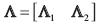
where

whence the six eigenforces are obtained, with five digits, as

the corresponding eigenpitches being, with four digits,
]]>
Notice that the eigenvalues returned by the eigensolver convey misleading information: the numerical values of two are close to three times those of the other four; this may lead one to think that the system is much stiffer in two "directions" than in the other four. However, the eigenforces and eigenpitches reveal that there are, in fact, four "directions" much stiffer than the other two. The four "directions" in question are those of the parasitical motions.
Further, the six unit vectors ei are given in the 3x6 array E below—not to be confused with CPM(e)!—as
E=[E1E2]
where

The six eigenscrews are now displayed in a 6 x 6 array S:
S = [ S1 S2 ]
where
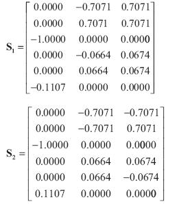
i closest to the origin are all zero. Therefore, all screw axes pass through the centroid O of the proofmass. Not only this. Four screw axes lie in the x-y plane, two on the z axis, which is in agreement with the symmetric layout of the structure. However, contrary to one's intuition, one cannot speak of principal translational and rotational stiffnesses, as none of the eigenpitches is either zero—for rotational motion—or infinite—for transbtional motion. All six eigenpitches are finite and nonzero, although four are one order of magnitude smaller than the other two. These correspond to the parasitical motions.
Conclusions
The generalized eigenvalue problem associated with the Cartesian stiffness matrix was revisited. The eigenvalues of the matrix were found to have the physical interpretation of forces, for which reason they are termed eigenforces. The eigenvectors, represented as unit screws, are termed eigenscrews. Further, the generalized eigenvalues, and hence, the eigenforces, were proven to occur in real, symmetric pairs, while the product of each eigenvalue by the pitch of its corresponding eigenscrew was shown to be non-negative. A procedure was proposed to calculate the eigenscrews from the generalized eigenvalues and eigenvectors returned by a numerical eigensolver, as available in scientific software. A numerical example was included, pertaining to the stiffness analysis of an accelerometer of millimetric dimensions, to illustrate the concepts discussed here. It should be apparent that the paper objective, to contribute to the understanding of the intrinsic properties of the Cartesian stiffness matrix, was met.
Acknowledgements
The research work reported here has been funded by Canada's Natural Sciences and Engineering Research Council, Quebec's Fond québécois de la recherche sur la nature et les technologies and a James McGill Professorship.
References
Angeles, J., 1998, "The application of dual algebra to kinematic analysis," in Angeles, J. and Zakhariev, E. (editors), Computational Methods in Mechanical Systems, Springer-Verlag, Heidelberg, Vol. 161, pp. 3-31. [ Links ]
Angeles, J., 2007, Fundamentals of Robotic Mechanical Systems. Theory, Methods and Algorithms, Springer, New York. [ Links ]
Ciblak, N. and Lipkin, H., 1999, "Synthesis of Cartesian stiffness for robotic applications," Proc. IEEE Int. Conf. Robotics and Automation, Detroit, MI, pp. 2147-2152. [ Links ]
Ding, X. and Selig, J,M,m 2004, "On the compliance of coiled springs," Int. J. Mechanical Sciences, Vol. 46, pp. 703-727. [ Links ]
Griffis, M. and Duffy, J., 1993, "Global stiffness modeling of a class of simple compliant couplings," Mechanism and Machine Theory, Vol. 28, No. 2, pp. 207-224. [ Links ]
Huang, S. and Schimmels, J.M., 1998, "The bounds and realization of spatial stiffnesses achieved with simple springs connected in parallel," IEEE Transactions on Robotics and Automation, Vol. 14, No. 3, pp. 466-475. [ Links ]
Huang, S. and Schimmels, J.M., 2000, "The bounds and realization of spatial compliances achieved with simple serial elastic mechanisms," IEEE Transactions on Robotics and Automation, Vol. 16, No. 1, pp. 99-103. [ Links ]
Kim, C.J., 2008, "Functional characterization of compliant building blocks utilizing eigentwists and eigenwrenches," Proc. ASME International Design Engineering Technical Conferences & Computers and Information in Engineering Conference, DETC2008-49267, Brooklyn, NY, Aug. 3-6. [ Links ]
Kövecses, J. and Ebrahimi, S., 2009, "Parameter analysis and normalization for the dynamics and design of multibody systems," ASME J. Computational and Nonlinear Dynamics, Vol. 4, pp. 031008-1-031008-10. [ Links ]
Loncaric, J., 1987, "Normal forms of stiffness and compliance matrices," IEEE J. Robotics and Automation, Vol. RA-3, No. 6, pp. 567-572. [ Links ]
Su, H.-J., Dorozhkin, D.V. and Vance, J.M., 2009, "A screw theory approach for the conceptual design of flexible joints for compliant mechanisms," ASME J. Mechanisms and Robotics, Vol. 1, pp. 041-009-1-041-009-8. [ Links ]
Synge, J.L., 1960, "Classical Dynamics", in Flügge, S. (editor), Encyclopedia of Physics, Vol. III/1, Springer-Verlag, Berlin, pp. 1-225. [ Links ]
Zwillinger, D. (editor), 2002, CRC Standard Mathematical Tables and Formulae, 31st Ed., CRC Press, Troy, NY. [ Links ]
1 these concepts are limited to 3.
2Overdeterminacy is only formal, as the four equations are consistent.
3Its singular values are all identical to each other.
]]> 4If Krr turns out to be singular, then an alternative formula is available, that relies on the nonsingularity of Ktt.5The reader can readily realize that, if one particular solution p of eq. (35) has been found, then pi + αei, with α ∈ , also verifies the above equation.