


 nueva página del texto (beta)
 Inglés (pdf)
 Artículo en XML
 Referencias del artículo
 Enviar artículo por email
 Citado por SciELO
  Similares en
SciELO
Similares en
SciELO 
 Permalink
1. Introduction
Packaging and containers industries widely use polymers due to their excellent mechanical properties, thermal properties, and chemical resistance 1. For the fabrication of polymeric parts, the injection molding process is one of the most important, and it is used to process more than 1/3 of all plastic pieces 2), (3. This manufacturing process is widely used in civil and mechanical construction, automotive components, aerospace, aeronautical industries, transportation equipment, and household products 4. Product and part design are essential areas related to plastic injection molding design, all of which contribute to the quality of the molded product and production efficiency 5. This process involves many process parameters such as melt temperature, gate design, filling, and cooling times strongly affect both part quality and cycle time 6.
The injection molding process comprises four essential stages: mold cavity filling, melt packing, solidification (cooling), and ejection 7. Although one of the most critical stages in the cycle is the cooling time, it plays a crucial role in injection molding by taking more than half of the molding cycle time and affecting the plastic part's final quality and mold productivity 8.
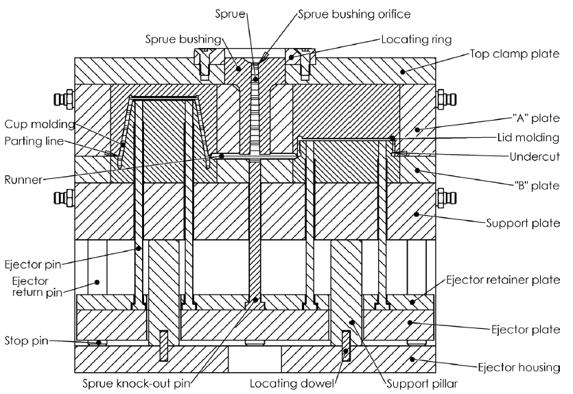
The general mold design has two parts: the creation of the part and the design of the mold 9. The mold design includes the mold base, designing the core and cavity, components, coolant channels, creating returning pin, adding ejector pin, creating gate and runner, adding locating ring and sprue bushing in sequence 10.
A two-plate mold with some of the essential components and parts is shown in Figure 1 11.
Generally, the cooling mold pars are manufactured by standard processes that consist of a pattern of drilled holes to pass coolant through the mold plates and connected by hoses to form a continuous pathway 10. Many different cooling systems designs are used in practice. While many molds use straight lines, such designs are often not optimal 11. The layout of the cooling channels is currently carried out by experienced designers who usually take as a reference set of geometric criteria based on their experience and related to dimensional values of depth and separation between channels 12. When the injection process is completed, the filling time is only 20%, while the proportion for cooling is about 80%, so the cooling system is essential amongst the injection mold design factors 13.
Computers have aided the plastic injection mold design for an extended life cycle. Various authors have developed program systems that help engineers design part, mold, and selection injection molding parameters. 14. In many times the process to repair or redesign is not documented, and it depends on the experience and judgment of the designer + or the mold tooling room. Frequently, the repair or redesign of mold pieces inferred the development of new geometries, the manufacture of the same components but longer dimensions, or the exploration of new manufacturing processes and materials 15. In the case of redesigning applying additive manufacturing, there are plenty of opportunities, benefits, and freedoms, especially at the design part level 16.
The development of new mold pieces without the theoretical basis is complicated, mainly due to the lack of knowledge of the correct gain of efficiency or improved qualities. Therefore, the latest are fundamental reasons to implement a methodology to validate the Computer-Aided-Design (CAD) stage and ensure the efficiency of the repair or redesign process.
Mold reparations take a long time, especially the parts in contact with high wear due to closing pressures, wrong operation, or poor maintenance. When mold has worn out, the mold shut off areas show signs like dragging, compaction, rounded edges, or analyzing the injected part, where the presence of quality defects like a difference in thickness, heat marks, gas marks, scratches is evident or surface finishes. The reparation complexity and scope will depend on the size and construction of the mold. Generally, molds are tools designed and planned for a long-life cycle to facilitate the maintenance, repair, and replace components like spare parts. For example, a plastic part quality generates defects due to a wear insert at the cavity that needs to be repaired. In this case, it is easier to manufacture and adjust it rather than manufacture the entire cavity and adjust with components.
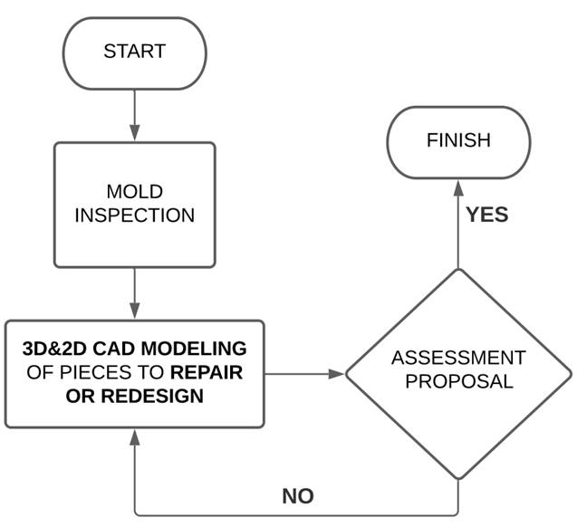
Repair workshops worldwide are scarce; hence when injection molds are simple with two or three plates, it is easier and cheaper to manufacture a new mold due to the complexity involved in repairing molds. On the contrary, it is easier to repair damaged parts by cutting molds to continue producing plastic parts due to complexity. Some of the main objectives and activities as a mold tooling room are repair molds, improving efficiency or product quality by a mold modification that can include the manufacture or redesign of new pieces, product updates, or injection runner system improvements. Getting better efficiency is an objective to follow in our mold reparations and redesigns. One of the most common workflows that consist of repairing or redesigning mold parts is shown in Figure 2. The process is short and effective when the reparation is easy, but the current approach is insufficient when considerable reparations or redesigns are needed.
Some methodologies have been successfully applied in additive manufacturing, as mentioned in 15. In the reference, the authors introduce a study case to create a Design for Additive Manufacture (DfAM) from a conventional manufacturing piece or an automated process to redesign mold cooling pieces 12. Generally, the implemented and documented methods are applied to the design and manufacture of molds and mold pieces, but no processes help in the redesign and repair of molds 15.
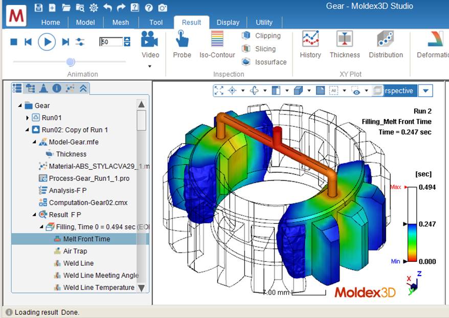
CAD software is helpful to design mold pieces and perform modifications that help model a correct mold part. However, CAD software and experience are not enough when it comes to new parts design. From this point, it is necessary to look for new engineering tools that give certainty that the redesigned part will behave as expected and improve in aspects such as the efficiency of the mold reflected in the quality of the final plastic product. After extensive research, commercial Computer Aided-Engineering (CAE) packages such as Moldex3D 17 or MOLDFLOW 18 are now widely used in practice to analyze a given part design o mold design 19. The CAE methods can predict temperature, pressures, times to improve the CAD stage and mold efficiency by simulating the injection plastic process 20. For example, Figure 3 shows an injection process simulation in Moldex3D.
A typical redesign process at the tooling workshop is implementing Hot Runner Systems (HRS) to old molds with Cold Runner Systems (CRS). HRS provides better parameters for injection molding and makes the most efficient process, an excellent reason to implement in almost all new molds 22. In the implementation of HRS, the engineering design have to consider a temperature increase, flow rate, turbulences by corners, injection point profiles, overheating in some pieces, into others 23. In practice, the implementation of HRS is necessary to redesign the cooling system, gate profile, and sprue bushings to avoid heating problems and make the most efficient injection process. CAE packages are widely used in the new cooling system design in HRS implementation 24.
In filling imbalance problems, CAE Software is widely used. The flows of molten polymers in injection molds are unsteady, non-Newtonian, and non-isothermal flows occur at very high deformation rates. Such complex flows can only be modeled numerically, e.g., using FEM (Finite element method) computations 25. It is necessary to remember that some factors like injection polymer melt pressure, temperature, shear rate, and others during the mold filling process will affect the melt rheological properties 26. In this context, a CAE tool can help predict the behavior to avoid quality problems.
The CAD-CAE integration system does not lead to modifying the analyzed model as an analysis result but predicts the behavior of the piece simulated 27. The following section presents the structured methodology proposed for redesigning and repairing mold parts implementing the CAE Validation.
2. Methodology to implement CAE Validation
Computational technologies are a widely used and essential tool for the engineering field, such as plastic mold design. Without a doubt, every facet of design, analysis, simulation, and manufacturing improves with the help of CAE techniques 28. However, the current repair and redesign plastic mold parts process rarely has a validation stage because sometimes new mold concepts are copied and applied to molds with old ideas, or repair is done based on the judgment and experience of the designer. Generally speaking, this practice can improve or worsen the mold's performance, so validating the CAD models through a Computer-Aided Engineering (CAE) stage is necessary to improve cooling parts, plastic flow, robustness, and others.
As is mentioned in 29, each mold designed has its process and specific knowledge. The initial stage design defines costs, delivery time, and mold manufacturability 30. In the process of redesigning and repairing plastic mold pieces, it is similar; the first step consists of analyzing the scope to set general objectives to achieve by the designer.
As an essential process of production and because of mold and product design, in 31, the authors perform a study about Taguchi's design of experiments to determine the optimal process parameters for injection molding to determinate mainly melt temperature, injection pressures, packing pressures, packing time, and cooling time.
The last examples are some of many methodologies to implement in the design of plastic products, plastic injection mold, or injection process, but now, applying these processes to the daily repair tasks may not work in the same way and provide good results. Therefore, the latest is a reason to develop an especial methodology to implement in our current redesign and repair process.
2.1 Redesign process methodology
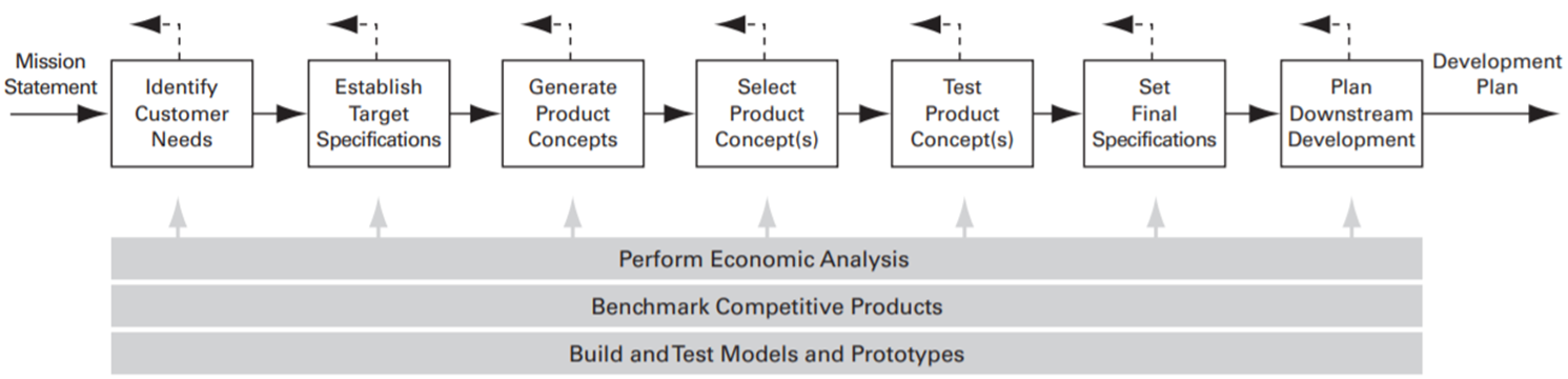
The proposed methodology is based on the front-end process for concept development. For example, see Figure 4, containing numerous interrelated activities, roughly ordered 32 and the already existing process (mentioned in the flow diagram in Figure 2) taking the essential stages, such as inspection and CAD modeling. Then to strengthen and improve the process, different locations were added.
The base of the current repair process is to define the scope, objectives, and specifications firstly achieved with the modeling and experience. The following steps correspond to implementing the validation stage through a CAE application, which should guide the way forward; it means adding extra steps for the prototyping and selection before CAE simulations. Based on the general lineal process of the design shown in Figure 5 33, the different stages through product design from a "Problem Identification" to "Result in Documents" are followed.
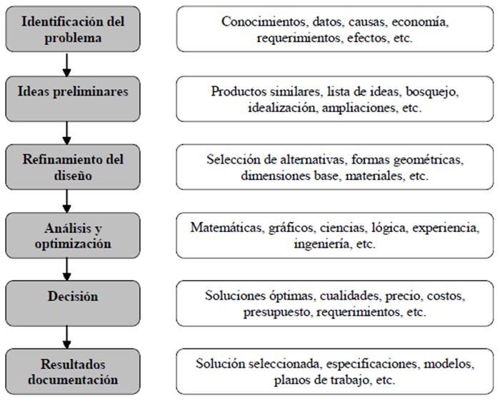
Next is depicted the proposed methodology to implement in the redesigning and repairing process, Figure 6.
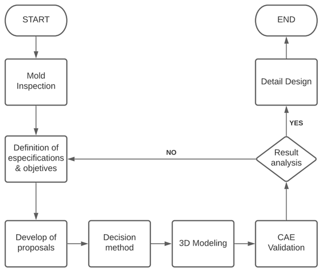
The first step is the physical inspection of the mold and plastic part, with the respective documentation for the final stages. After mold inspection, the second step is" Establish specifications and objectives" that help define the scope of the repair, considering the current conditions of the mold, characteristics of the plastic part, and behavior of the tooling in production. The final stage corresponds with why repair or implement the redesign, focusing on one or more problems.
The specifications and definitions of the CAD problems are established under features related to improvement and validation 12. In addition, it is necessary to define specific materials and geometries as they are redesigned into new parts.
Once the proposal is defined, the next step, "Prototypes selection," is used to choose the best option (by a decision matrix method). That allows identifying, analyzing, and evaluating the different proposals raised 32 and selecting the best one that sticks to the repairing program, cost, machinability, and other aspects to consider.
The CAD model is defined with the CAE system's necessary characteristics to make decisions 5. The fifth step consists of the Prototypes debugging: "CAE Validation," which, by applying temperatures, pressures, injection, or mold conditions, it is possible to know if the CAD product concept will behave according to the proposed stage two. This stage helps know if the specified materials and geometries are adequate to meet the objectives and specifications previously set up or achieve a theoretical gain in cooling efficiency or part robustness.
The sixth step is crucial for the process: "Result from the analysis." This step is based on the analysis, and the decision to continue must be taken towards the final stage or return to step two and redefine the problem. Although this may not always be the case, if the analysis of results is not consistent, it is possible to return to the previous step and validate that the boundary conditions were correctly applied, in this way, ensuring the integrity of the results.
Once a CAE stage has validated the results, the methodology finishes in the seventh step, "Detail design," which includes the complete specification of the geometry, materials, and tolerances of all unique parts of the product. This stage provides product control documents, that is, the drawings or files that describe the geometry of the pieces (32); in the operation of redesign or repair, the assessment is an important file.
3. A repair case study
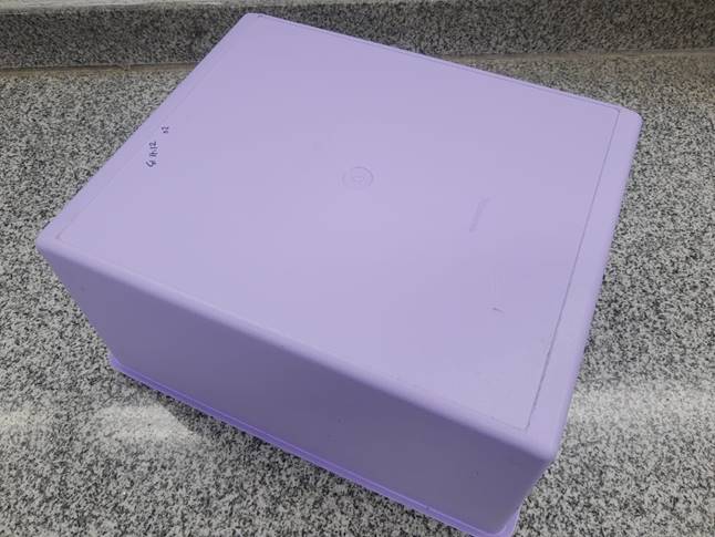
In this case, a base cavity insert redesign is achieved through two objectives: update the hot runner injection system and improve the cooling at this piece. From the literature, it is very well known that changing the injection system from cold runner to hot runner will increase the heat transfer. Hence it is necessary to redesign the cooling system. The proposed methodology in Figure 6 is used in this case study to prove the new stages. Due to that, the first stage, "Mold Inspection," must be a physical activity and has no changes in process (see Figure 2); this case study will start in step two, "Definition of specifications and objectives." The plastic product to analyze is a 30 liters capacity rectangular container, see Figure 7.
3.1 Definition of specifications and objectives
After "Mold Inspection," it is possible to start the establishment of the Objectives and Specifications:
Specifications:
1. Keep original sizes of the piece; it must consider a refurbish to assembly.
2. The surface molding finishes must be the same.
3. Apply the newest design standards.
Objectives:
1. Make three independent flow water-cooling circuits.
2. Keep an almost equal heat transfer on molding surfaces.
3. Know the gain heat transfer.
4. Make the CAE validation with two different materials in sprue bushing.
The specifications and objectives were established by mold repair and redesign pieces experience; the designer can add more during the process.
3.2 Develop of proposals
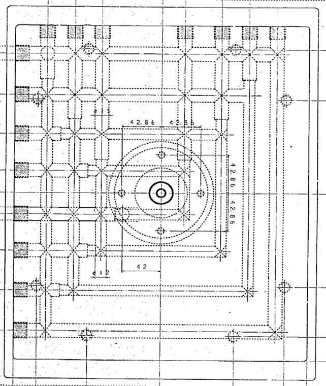
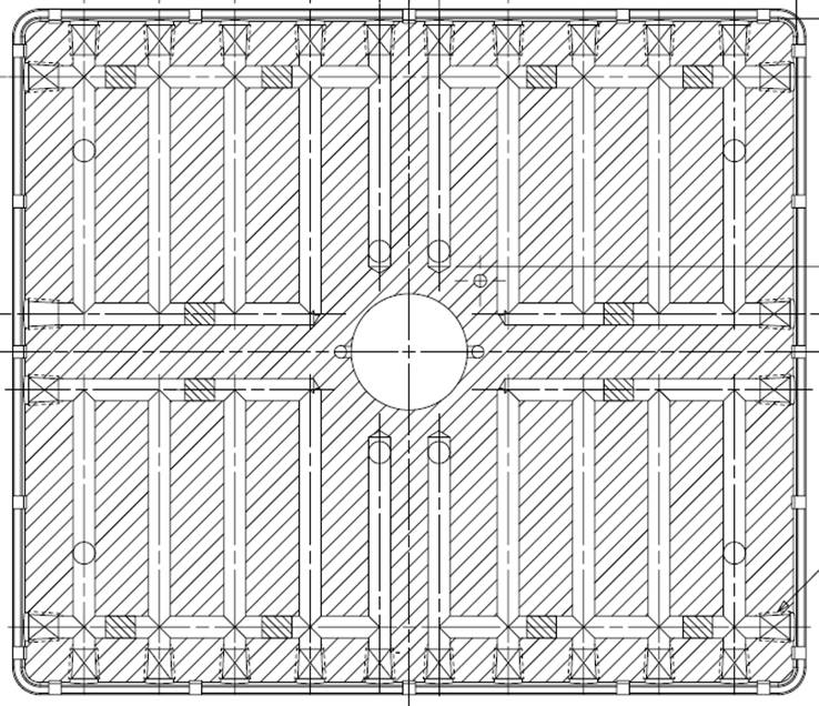
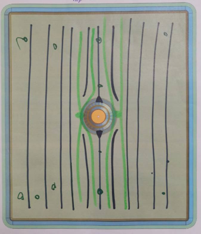
The original design (the original cavity, made in 1989, is shown in Figure 8.) offers a piece with a "grid" of holes and copper plugs to create a flow water circuit; in this design, the sprue bushing does not have a water-cooling.
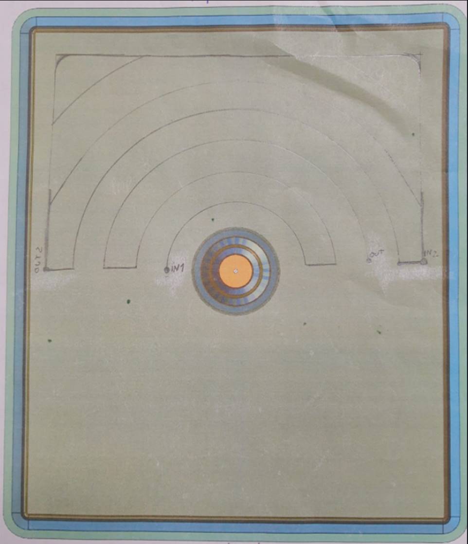
The cooling circuit shown in Figure 9, once implemented in a similar plastic product of 20 liters of capacity, produced the cycle time was improved in 8 seconds, with the advantage of an evident reduction of the quality defects.
Uniform flow distribution helps improve the thermal conductivity of coolant, cooler parts, and heat transfer applications in medical, fuel cells, solar panels 34. However, having a maldistribution in high heat flux cooler parts will be a reason to decrease efficiency systems 35.
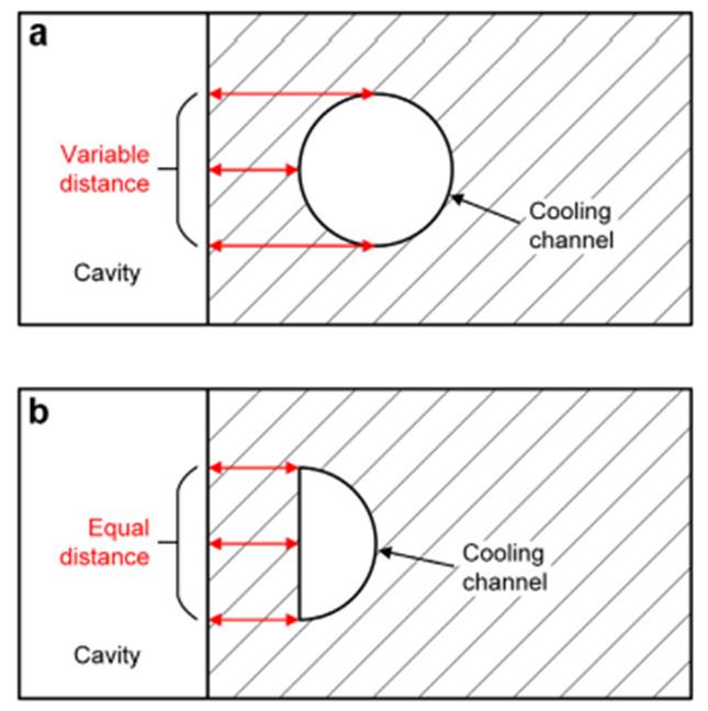
Although circular cross-sections are the most common profiles 10, additive manufacturing explores other non-circular section cooling profiles such as square, rectangular, diamond elliptical, trapezoidal, and other polygons 36. Notwithstanding, this manufacturing technique is expensive. This research considers two cross-section cooling profiles: circular and half-circular (see Figure 10). In the first case, Figure 10a has a non-constant distance between the molding surface and the CC (cooling channel) surface; this problem could be solved by a parallel section CC to the molding surface as shown in Figure 10b, further, to enhance the uniformity of heat dissipation 37.
The proposals consider keeping the original sizes but manufactured in two pieces to make an internal continuous water channel. In general, the fabrication of old parts corresponded to one steel piece.
As a sub-step, sketches were developed to analyze different ways to improve the system cooling in configurations and cross-section profiles. Finally, the CAD models are defined the coolant inlet and outlet.
The parts' manufacturing dimensions are 420.0 x 380.0 x 85.0 mm; it is then expensive to use additive manufacturing to create an internal cooling system. The solution to this inconvenience is to divide the mold part into two pieces: base cavity and insert Figure 18. This manufacturing method helps to design a particular channel configuration, as shown in the following proposal sketches.
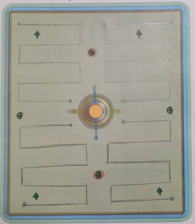
The first proposal consists of two parts and two milled channels. It is necessary to think about the simplest way to refresh the cavity base, with two inlet/outlet and sprue cooling circuits. The inconvenience of this configuration could be the distance route; probably at a medium distance, the water is hot, see Figure 11. Finally, the proposed channel profile is rectangular.
Regarding proposal two: it considers four circuit drilled channels. Here, the main idea is due to a similar product geometry in its container and good cooling results obtained to implement these drilled hole configurations (see Figure 12).
Proposal 3 comes from various equal distributions 35; the main problem is the space between the inlet/outlet water; in this case, there is no way to the coolant, see Figure 13.
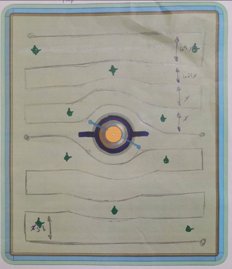
Fourth proposal: considers two parts and the circular milled channels taking advantage of the plastic distribution inside the cavity. It is needed to remark that the cooling configuration is made by a radius from the center to edges to get a better heat distribution by the rectangular profile channel to the injected plastic flow, as shown in Figure 14.
3.3 Decision Method
Concept selection is an extensive process that can include sub-iterative stages associated with concept generation and testing. A design team can refine and improve concepts by ways such as concepts screening and scoring 32.
Once the general concept of the scheme has been developed, it is necessary to carry out the process of selecting one or two proposals to perform the numerical simulation for the new mold part.
The process of "Concept Screening" aims to narrow the number of concepts quickly and improve them. Table 1 shows the scoring.
Table 1 The concept screening matrix.
| Concepts | |||||
|---|---|---|---|---|---|
| Selection criteria | Old cooling (REF) | 4 Circuit drilled channels | 2 parts, 2 milled chanels | 2 parts, manifoldequal distribution | 2 parts, circular milled chanels |
| Economic | |||||
| Use of steel | 0 | 0 | - | - | - |
| Manufacturing hours | 0 | 0 | - | - | - |
| Fitting hours | 0 | 0 | - | - | - |
| Temper | 0 | 0 | - | - | - |
| Manufacturing | |||||
| Facility to manufacture | 0 | 0 | 0 | 0 | 0 |
| Design | |||||
| Cooling set | 0 | - | - | + | + |
| Cooling channel profile | 0 | - | + | + | |
| Inovative | 0 | 0 | + | + | + |
| Facility to Inlet | 0 | + | + | - | + |
| Facility to Outlet | 0 | + | + | - | + |
| Use update standard | 0 | - | + | + | + |
| Fitting process | |||||
| Facility to fitting | 0 | 0 | - | - | - |
| Use of Plugs | 0 | - | + | + | + |
| Sum +´s | 2 | 6 | 5 | 7 | |
| 1S6um 0´s | 14 | 8 | 1 | 1 | 1 |
| Sum -´s | 4 | 8 | 8 | 6 | |
| Net Score | 0 | -2 | -2 | -3 | 1 |
| Rank | 2 | 2 | 3 | 1 | |
| Continue? | YES | YES | NO | YES | |
The selection process in the screening matrix is based on general information to delete or improve the proposals. The characteristics to evaluate the "Scoring process" are more specific and help a team choose one or two options for the following product development stage. Because the variables involved are economical, manufacturing, fitting, and design, it is impossible to place an Equitable evaluation scale. Generally, it is easiest to focus a discussion by rating all the concepts concerning one criterion at a time, as shown in Table 2.
Table 2 Rate the concepts
| Relative perotmance | Rating |
|---|---|
| Much worse than reference | 1 |
| Worse than reference | 2 |
| Same as reference | 3 |
| Betrher than reference | 4 |
| Much better than reference | 5 |
Table 3 presents the final scoring selection matrix.
Table 3 The scoring matrix.
| Concepts | |||||||||
|---|---|---|---|---|---|---|---|---|---|
| Old Cooling (REF) | 4 Circuit drilled channels | 2 parts, 2 milled chanels | 2 parts, circular milled chanels | ||||||
| Selection criteria | Wheight | Rating | Score | Rating | Score | Rating | Score | Rating | Score |
| Economic | 40% | 0 | |||||||
| Use of steel | 5 | 3 | 0.15 | 3 | 0.15 | 2 | 0.1 | 2 | 0.1 |
| Manufacturing hours | 10 | 3 | 0.3 | 3 | 0.3 | 2 | 0.2 | 1 | 0.1 |
| Fitting hours | 10 | 3 | 0.3 | 3 | 0.3 | 2 | 0.2 | 2 | 0.2 |
| Meteorology hours | 5 | 33 | 0.15 | 3 | 0.15 | 2 | 0.1 | 2 | 0.1 |
| Temper | 10 | 3 | 0.3 | 3 | 0.3 | 3 | 0.3 | 3 | 0.3 |
| Manufacturing | 10% | ||||||||
| Facility to manufacture | 10 | 3 | 0.3 | 3 | 0.3 | 2 | 0.2 | 2 | 0.2 |
| Design | 40% | ||||||||
| Cooling set | 10 | 3 | 0.3 | 4 | 0.4 | 2 | 0.2 | 5 | 0.5 |
| Cooling channel profile | 10 | 3 | 0.3 | 3 | 0.3 | 5 | 0.5 | 5 | 0.5 |
| Inovative | 5 | 3 | 0.15 | 3 | 0.15 | 4 | 0.2 | 5 | 0.25 |
| Facility to Inlet | 5 | 3 | 0.15 | 4 | 0.2 | 2 | 0.1 | 5 | 0.25 |
| Facility to Outlet | 5 | 3 | 0.15 | 4 | 0.2 | 2 | 0.1 | 5 | 0.25 |
| Use update standard | 5 | 3 | 0.15 | 3 | 0.15 | 4 | 0.2 | 5 | 0.25 |
| Fitting process | 10% | ||||||||
| Facility to fitting | 5 | 3 | 0.15 | 3 | 0.15 | 4 | 0.2 | 4 | 0.2 |
| Use of Plugs | 5 | 3 | 0.15 | 3 | 0.15 | 5 | 0.25 | 5 | 0.25 |
| Next Score | 3 | 3.2 | 2.85 | 3.45 | |||||
| Rank | 3 | 2 | 4 | 1 | |||||
| Coninue? | To simulate | To simulate | NO | To simulate | |||||
According to the scoring selection matrix, the best proposal to simulate is the fourth concept which considers two parts and circular milled channels. However, as mentioned previously, the implemented idea in proposal two is similar to a previous product. Therefore, a numerical simulation of the current cooling system will be performed as a reference.
3.4 Develop 3D models
The geometries considered in the following proposals were developed in the CAD software of the company Siemens, denominated NX 12 38.
Proposal 1
Here the consideration goes to the original design (see Figure 8); in this way, the correct heat distribution could be known and give another reason to redesign the current cooling system knowing the zones with bad heat transfer, to implement the new HR system.
Proposal 2
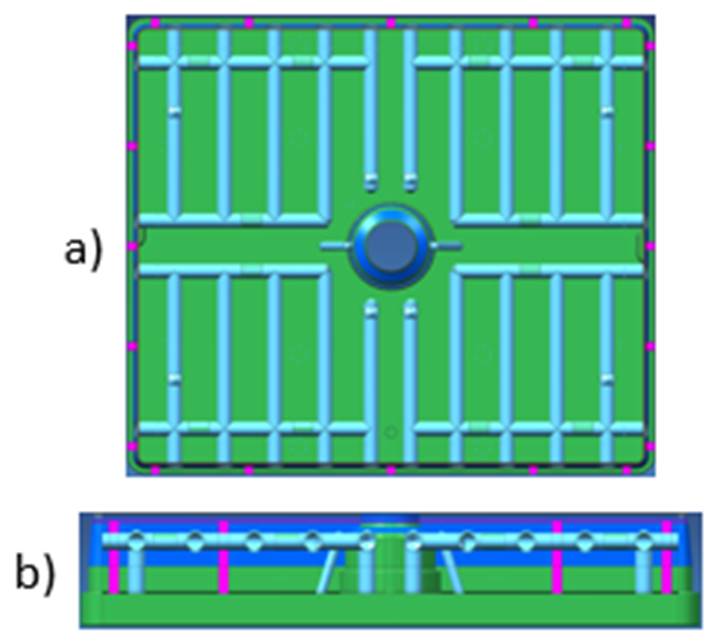
In this proposal, drilled holes are made through the steel piece to create a continuous water circuit, manufacturing in one steel piece; see Figure 15a to Top view and Figure 15b for cross-section view.
Proposal 3
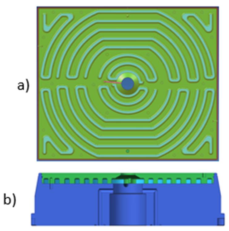
The cooling circuit set designed in this consideration needs to have a correct fix configuration and a balanced inlet/outlet water; Top view and a cross-section view are shown in Figure 16a and Figure 16b as corresponding.
3.5 CAE validation
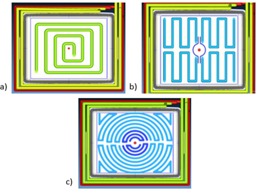
The objective of the simulation is to know the temperatures of plastic, flow, and cooling behavior to analyze if a new cooling system will be good or bad. The numerical simulations were performed in Moldex3D, software for injection plastic simulation. First, the cooling and product were modeled to a case setting. Second, the proposed cooling cases, current cavity, and core cooling had to be modeled according to original specifications. Next, Figure 17a presents the current circuit cooling modeled in green; then, Figure 17b shows the final cooling proposal 2 with sprue bushing cooling and four inlet/outlet. Finally, Figure 17c shows the milled circular cooling circuit of proposal 3.
The numerical simulation mesh was performed, as shown in Table 4.
Table 4 Characteristics of the numerical simulation meshes.
| Simulathion Cases | ||||
|---|---|---|---|---|
| Case | Proposal | Mesh type | Solid mesh elements | Part element |
| 1 | Current cooling system | Solid | 12,336,957 | 1,906,919 |
| 2 | 4circit drilled holes | Solid | 12,697,834 | 2,046,808 |
| 3 | Circular circuit, milled channels | Solid | 13 719 226 | 2,046,808 |
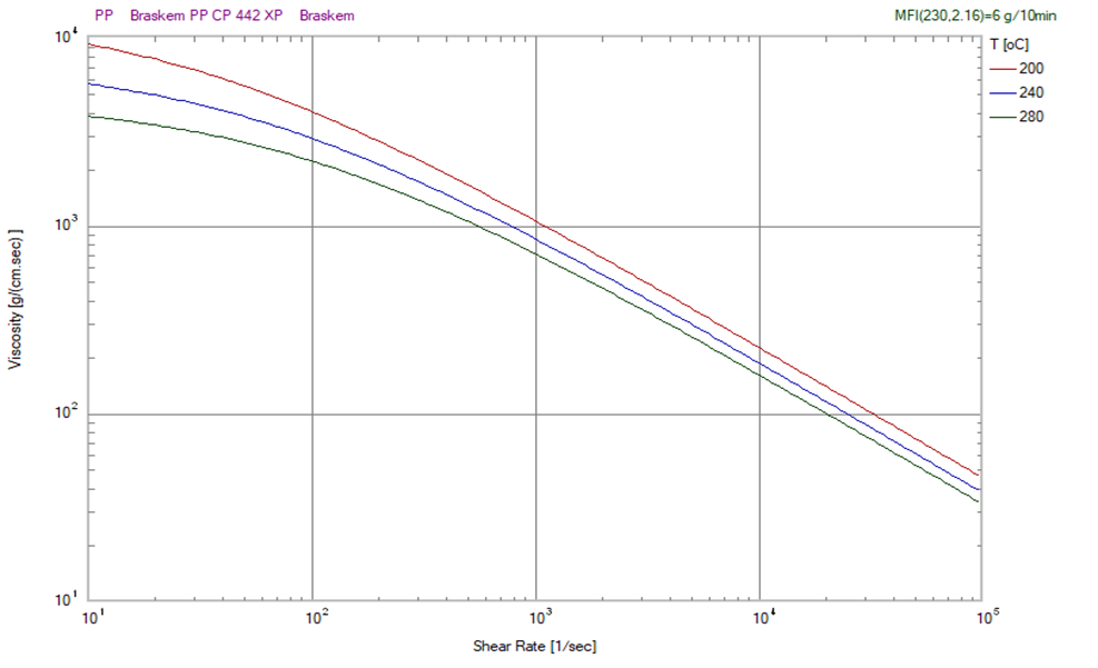
The used polymer was a Polypropylene (PP), Braskem manufactured with the grade name Braskem PP CP 442 XP, with a viscosity behavior shown in Figure 18.
The injection process was performed with parameters shown in Table 5.
Table 5 Process condition parameters.
| Process Ccondition | ||||
|---|---|---|---|---|
| Item name | Current cooling system | 4circit drilled holes | Circular circuit, milled channels | |
| Filling | Filling time | 4 sec | 5.22 Sec | 5.22 Sec |
| Mold temperature | 200 °C | 230 °C | ||
| Mold temperature | 35 °C | 35 °C | 35 °C | |
| Max. Pressure | 140 MPa | 140 MPa | 140 MPa | |
| Injection volume | 1391 cc | 1391 cc | 1391 cc | |
| Inyection system | Cold Runner | Hot Runner | Hot Runner | |
| Packing | P. Time | 4 sec | 4 sec | 4 sec |
| Max. Pressure | 140 MPa | 140 MPa | 140 MPa | |
| Coling | Cooling time | 7 Sec | 7 Sec | 7 Sec |
| Ejection temp. | 108 °C | 108 °C | 108 °C | |
| Air temperature | 25 °C | 25 °C | 25 °C | |
Once the process is OK and saved, continue to analysis type. To this simulation, a "F P C W" (Filling, Packing, Cooling, and Warpage) was selected to get Injection results. Now, the numerical simulation can be performed for the data analysis.
3.5 Result Analysis
The interpretation of the results is crucial for repairing or redesigning the mold or molding parts. It is derived from comparing the two results vs. the original cooling concept.
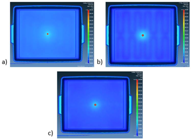
The cooling temperatures show the distribution of the current plastic product. In Proposal 2, Figure 19b, a difference in cooling temperature is visible due to variable distance from molding area to drilled hole; this is a cause of defects like warpage and deformation or different shrinkage. In proposal 1, the difference is minor according to cold runner injection, Figure 19a. Proposal 3, Figure 19c, has a good temperature distribution due to equal distance from molding surface to cooling channel; this helps to reduce quality defects like deformation.
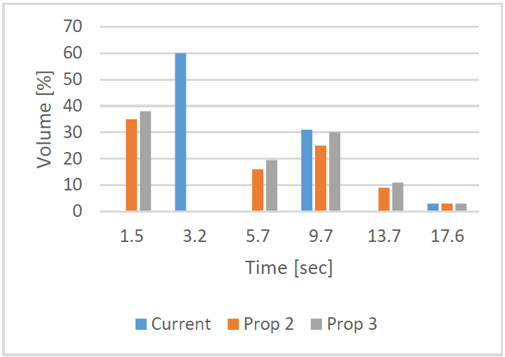
According to the polymer maker, the safe time to reach ejection temperature (TTRET) is when the plastic part is at the temperature of 108°C or lower. Therefore, due to a cold runner injection and minor injection temperature, the best option is proposal 1, with a TTRET average of 4.4 secs with 65% of total volume, Figure 20. Proposals 2 and 3 have a similar behavior due to injection setup, but the injection parameters are different to make the injection process better and increase the temperature. The result is a better response in the cooling system, see Figure 20.
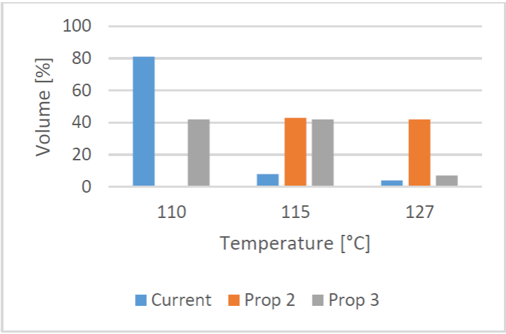
With the current cooling system, Figure 17a, the maximum cooling temperature in thickness is 110°C in 81% of total volume. Therefore, the best option is proposal 3; according to figure 21, 41% of the volume is at 110°C, and 42% is at 115°C; instead, proposal 2 the 42% is 127°C, heater that proposal 3 and current condition.
The mold temperature differences (Figure 22) show the final cavity and core at the end of cooling time; even proposals 1 and 3 have good heat conductivity. Proposal 3 is the best due to a higher injection temperature, Figure 22c. Proposal 1, Figure 22a, has a good mold temperatures distribution with an average of 10°C. Proposal 3, Figure 22b, shows the heat transfer pattern due to the profile cooling channel; its design has cooler lines caused by the circular drilled channel.
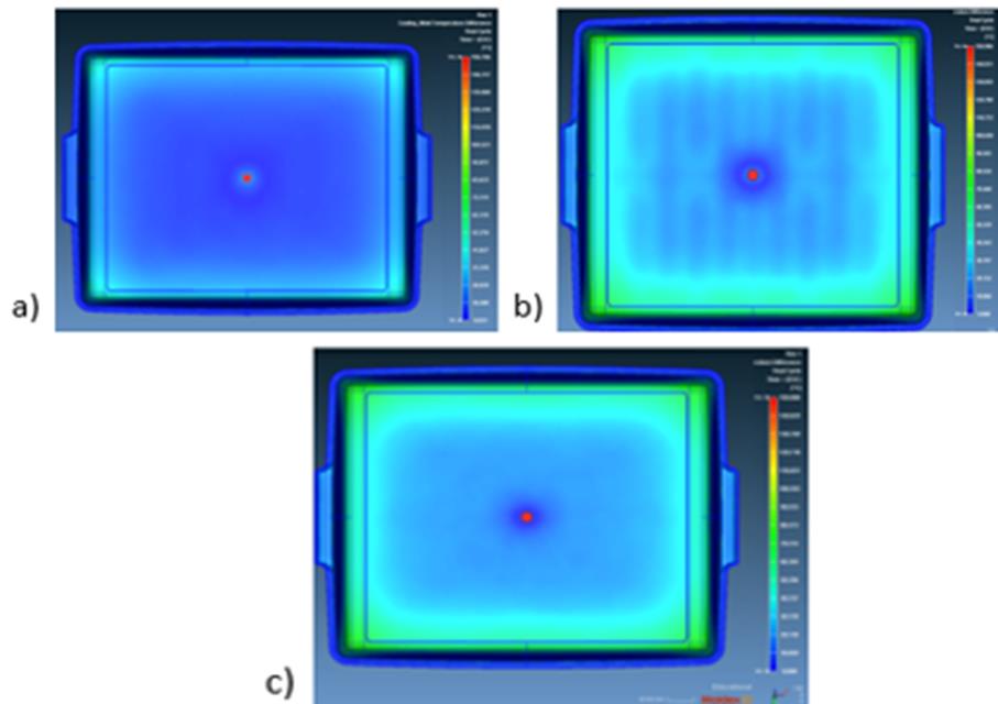
Even proposals two and three have similar behavior. Therefore, the best option is proposal three due proposal two has a different heat difference. However, this will cause problems like deformation, heat zones, and a higher cycle time.
3.5 Detail design
Once the analysis of the results, it is necessary to work on the final dimensions of the 3D models, create the 2D drawings (with GD&T specifications) and finalize the assessment format to indicate processes and sub-processes involved in the parts modified. Finally, it is necessary to detail the critical aspects in the 3D models, the 2D drawings (exploded and assembled), BOM (for large assemblies), and assessment.
4. Conclusions
The proposed methodology can be used for repairs and redesign. In this research, the results were essential to making the right decisions about CAD Models to simulate, what kind of results to calculate and analyze, and finally, define the proper way to take in repair or redesign with a CAE-Theoretical base.
The validation by Computer-Aided Engineering is a stage that reinforces the designer's experience and facilitates decision-making for inexperienced engineers in the repair and redesign of molded parts.
In this study, the results are significant for choosing an accurate cooling system to reduce cooling cycle time, improve the quality of plastic products, and avoid different temperatures during the cooling stage. Otherwise, the mold modification could be implemented in a cooling system like Figure 15, causing cooling problems and quality issues like deformation.
The numerical simulation helped avoid the mold repair, rework and carry out a successful repair in a single intervention, avoiding production delays, reprogramming the production of molds, and wasting time due to a machine without a mold. The methodology to implement CAE validation is a tool that modifies the process of redesigning and reparation of molded parts. At first glance, it seems to lengthen the process, but the reward of that extra time of analysis and validation consists of avoiding the rework of a failed repair.

