


 nueva página del texto (beta)
 Inglés (pdf)
 Artículo en XML
 Referencias del artículo
 Enviar artículo por email
 Citado por SciELO
  Similares en
SciELO
Similares en
SciELO 
 Permalink
Introduction
Spinal pedicle screws, first introduced by Boucher in 19591 and popularized by Roy-Camille in the 1960s,2 offer secure vertebral grip that enables improved correction and maintenance of rigid internal immobilization. In 1962, Harrington applied this procedure for the surgical correction of scoliosis inserting screws through the isthmus of the pedicle. Thereafter, many other professionals improved this technique to treat spinal deformity.3,4,5,6,7
After Vaccaro’s papers on the morphometric analysis of the thoracic vertebrae,8 the use of pedicle screw-based spinal instrumentation systems, on the lumbar and thoracic spine, increased tremendously due to their superior biomechanical properties.9 Since 1992 other methods of fixation were abandoned as the use of screws offered better intraoperative control and postoperative results. Posterior corrective surgeries using pedicle screw constructions, which allow correcting curves in three dimensions, has become the most popular treatment for scoliosis,10 but represents a challenge for the spine surgeon for fear of catastrophic complications by malposition or overpenetration related to the placement of thoracic pedicle screws in particular.11 The most common injury associated with misplaced thoracic pedicle screws is neurologic complication. Unfortunately, it can result not only in injuries to the spinal cord, but also, when invading the thoracic cavity, injuries to vital vascular and visceral structures.12
The number of patients with malpositioned screws in whole-spine procedures has been reported in limited number of studies. This varies from 1.2 to 20%, with a fairly consistent rate around 15% when CT scans were consistently obtained.13,14,15 Use of image-guide systems for pedicle screw fixation was introduced in the mid 1990s. Those systems rely on the use of fluoroscopic, CT-guide and/or electromagnetic field-based navigation to aid in accurate placement of pedicle screws.16 However, even with the use of image-guide navigation the rate of pedicle wall perforation has been reported between 1.2 to 4.3%.17 Thus, techniques to optimize placement and guarantee intraosseous pedicle screw position must be promoted to achieve safer thoracic screw placement.18
Here we present five cases of deformity correction utilizing a new technique of pedicle screw placement using sequential and multilevel navigational templates consisting of tubular plastic drill assisted-guides generated by the patient-specific 3D CT reconstruction model.
Clinical cases
Five cases with the diagnosis of idiopathic scoliosis were operated, whose clinical characteristics are presented in Table 1. All cases were evaluated with preoperative radiographs taken in standing position. Curves were evaluated using the Cob technique, as well as the pelvic parameters. It was performed in all patients Low-radiation tomography, with reconstructions in third dimension. Correction of the deformity was determined by comparing the postoperative and preoperative radiographs. The mean angle of the main curve in each case was measured with the Cob angle in preoperatory and postoperatory (Figures 1 and 2).
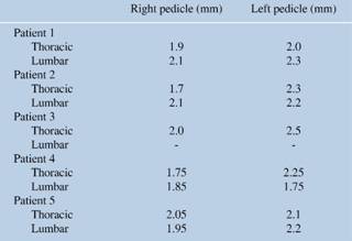
Table 1: Profile of the patients: gender, age, number of screws used and the degree of correction obtained in the main curve.
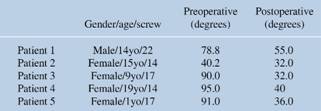
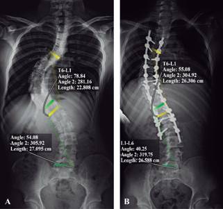
Figure 1: Coronal radiographs with Cobb’s angle measured in major thoracic (T6-L1) and lumbar (L1-L6) curves before (A) and after (B) deformity correction.
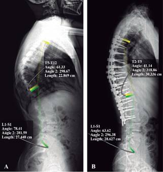
Figure 2: Lateral radiographs with Cobb’s angle measured in thoracic kyphosis (T5-T12) and lumbar lordosis (L1-S1) before (A) and after (B) deformity correction.
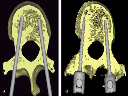
3D reconstruction model and patients-specific surgical technique: A high-accuracy 3D CT Scanner (Lightspeed; GE Healthcare) with a slice thickness of 5 mm and prospective reconstruction of 0.625 mm were used to obtain preoperative images, which were obtained with the patient in the surgical position (Figures 3A to 3D). Then, these images were exported in the DICOM format to 3D/multiplanar imaging software in order to reconstruct all planes and trace the screw trajectories using bone and STN filters (Figures 4A and 4B,Figure 5). With this reconstruction we printed patient-specific 3D multilevel templates (Figures 6A to 6C) as well as the complete scoliotic plastic model in ABS (acrylonitrile butadiene styrene) plastic using stereolithography. Every template was created as the inverse surface of the vertebra posterior surface and designed to fit and lock onto its spinous processes and lamina, bilaterally and multilevel. We generate two different sequential templates. The first template has complete cylinders with a hole with the minimal inner diameter of 4 mm to allow entry to both, the drill and awl (Figures 6A to 6C). After corroborating that the base of the cylinder was placed in the entry point planned, drilling could be performed accurately to perforate cortical bone (Figure 6A) followed by awl-assisted penetration of the pedicle and vertebral body (Figures 6B and 6C). The second template consists of hemi-cylinders with a wider inner diameter (6 mm) to allow correct orientation of the screw in direction/angulation with appropriate restriction of movement since the narrowest screw’s diameter we had available was 4.5 mm (Figure 6D). The main direction of the screw was planned to be, when possible, in the center of the pedicle and parallel to the superior endplate of the vertebrae. If the pedicle was excessively thin, as occur commonly in the concavity, we prefer the violation of the lateral wall of the pedicle instead of the medial wall trying to avoid injuring of the dura, spinal cord or nerve roots. The screw tip was planned to be posterior from the anterior cortex of the vertebra but 75% into the vertebral body. The coordinates of the bone entry point, the screw’s trajectory/angulation and, the tip of every screw were planned on preoperative CT scan images (Figure 7). In planning instrumentation from T5 to L3 (11 levels) for deformity correction, we [elected to] cut every template in 3 multilevel segments (3, 3 and 5 levels respectively), which allows better handling of the posterior vertebrae surface and accurate overlying of templates according to the prone position during surgery. With these two improvements, segmented multilevel templates and preoperative image acquisition in surgical position, we intend to resolve the lost of acuity in the sagittal plane. These sequential and segmental multilevel templates were tested for accuracy placing them onto the scoliotic plastic model to evaluate any cortical violation before surgery.
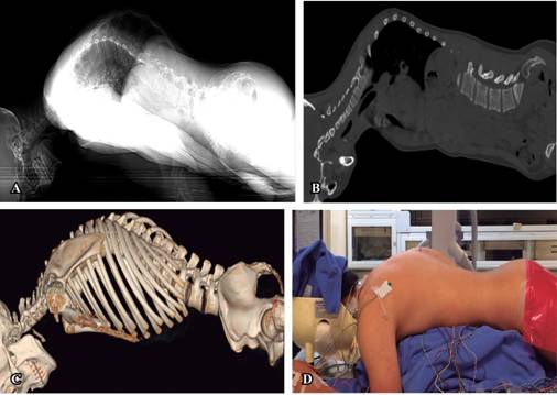
Figure 3: Preoperative images based on CT with the patient mimicking surgical position using chest rolls. (A) Topogram, (B) sagittal CT, (C) 3D image reconstruction in CT and, (D) patient in prone position before surgery.
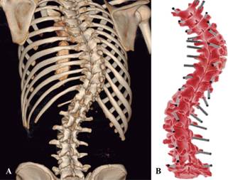
Figure 4: 3D image reconstruction in CT of the spinal deformity case (A) and, screw’s trajectory/angulation planning in all levels (B).
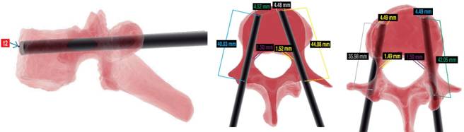
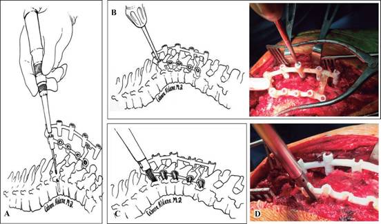
Figure 6: Use of one segment of sequential navigational templates. A-B) First template with complete cylinders which allow the access of a drill to perforate accurately the cortical bone in the entry point planned and, the awl to penetrate safely the cancelous bone of the pedicle. C-D) Second template with hemicylinders which allow access to the screw in the correct direction and angulation.
Results
After following clinical and image protocol for diagnosis, the decision of surgical management was established. Planning of surgical correction for deformity based on clinical and radiographs was made by the senior author in agreement with the rest of the staff of spine during one clinical case study session. Design and production of templates led by the biomedical engineer after planning the screw’s placement took 48h. The calculated cost of sequential navigational template production for complex deformity cases was around US$500.
Patients underwent correction deformity through posterior instrumentation using pedicle screw fixation with the use of multilevel sequential adjustment templates personalized navigation and intraoperative neuromonitorization. During surgery, X-rays and fluoroscopy were not used to confirm any screw trajectory with this method. There was no radiation throughout the procedure, which included placing a total of 84 screws, 45 thoracic and 39 lumbar levels without major changes («red alerts») in the monitoring. For safety reasons only fluoroscopy was performed to assess any loss before reversing the anesthesia. Postoperative radiographs in the standing position were taken later during hospitalization; however, the accuracy of this new method was evaluated by comparing tomographic scans obtained before and after surgery (Table 2), with prior consent informed by the legal representative, since the routine performance of computed tomography in the postoperative context is not justified. All screws were evaluated by tomography. The placement of the screws had a standard deviation of 1.9 mm in the right pedicles and 2.2 mm in the left pedicles. A greater than 2 mm violation was observed in the medial wall of the pedicles on 4 screws, however as it was in the concavity, no patient experiment had neurological complications. In 10 pedicles of the concavity, due to their small size, a lateral infraction of the pedicles was planned, with 4.5 mm diameter screws, so they are classified as grade 0 in the Mirzo classification (screw completely inside the pedicle without the violation of any cortical).19 Two pedicle screws of the convexity at the time of the reduction broke laterally the pedicle, without clinical repercussion. According to the classification based on the results of the placement of thoracic pedicle screws,20 which take into account an acceptable safety and biomechanical strength of thoracic pedicle screws when there is degree of malposition, of the 84 pedicle screws, 82 were classified as grade 1, or acceptable placement.
Discussion
Correction in scoliosis surgery has shifted from sublaminar wires and hooks to the pedicle screw system. Posterior spinal instrumentation fusion is the gold standard in the treatment of progressive idiopathic scoliosis worldwide today. There is growing evidence of the advantages of pedicle screws to achieve 3-column fixation and de-rotation the spine; provide improved coronal balance; and reach low pseudoarthrosis and implant failure rates.21
For thoracic pedicle screws used in spinal deformity treatment, screw misplacement incidence ranges from 3% to 25%, with screw-related neurologic complication incidence around 1.5%. However, the rate of misplacement is possibly higher, as much as ten times, since not all patients have been evaluated postoperatively with CT scan instead radiographs.11
Even if only a small fraction of misplaced screws actually cause any important complication,20 there are many important issues to take in consideration when thoracic pedicle screws are placed. Because of the oval configuration of the pedicle, the transverse dimension limits the usable screw diameter (pedicles between the fourth and twelfth thoracic vertebrae are usually ≥ 5 mm).8 Therefore, we used 4.5 mm diameter screws -the narrowest available. However, pedicles from the concave curve are even smaller than the convex one as we observed in the present case with most of them as cortical channels according to Watanabe-Lenke Classification.22 Rotated vertebrae are seen in thoracic scoliosis. The most rotated and apical vertebra was the ninth thoracic in the present case (Figure 8) and screw insertion here poses a great risk to surrounding structures. In addition, medial wall is thicker than lateral wall; therefore, tendency to violate lateral wall is most common. For this reason, we preferred and anticipated the violation of the lateral wall in our plan. Anterior advancement of a screw that has been placed laterally of the pedicle on the left side can endanger the lung, segmental vessels, and sympathetic chain (the fourth through twelfth thoracic vertebrae) and the aorta (the fifth through tenth thoracic vertebrae). On the right side, anterior advancement of screws that have been placed laterally can endanger the lung, segmental vessels, sympathetic chain and azygos vein (the fifth through eleven thoracic vertebrae). A breach of millimeters of the anterior and anterolateral cortical boundaries of the vertebral body may not initially damage the adjacent soft-tissue structures because the mobility of these structures. However, chronic irritation, especially due to the pulsatile aorta, may result in later damage. When screws that have been placed in the right thoracic pedicle are advanced beyond the anterior cortical margin of the vertebral body, they can endanger the superior intercostal vessels (the fourth and fifth thoracic vertebrae), the esophagus (the fourth through ninth thoracic vertebrae), the azigos vein (the fifth through eleventh thoracic vertebrae), the inferior vena cava (the eleventh and twelfth thoracic vertebrae), and the thoracic duct (the fourth through twelfth thoracic vertebrae). When screws that have been placed in the left thoracic pedicle are advanced beyond the anterior cortical margin of the vertebral body they can endanger the esophagus (the fourth through ninth thoracic vertebrae) and the aorta (the fifth through twelfth thoracic vertebrae).12 Therefore, the trajectory/angulation of the screw was planned taking into account that the tip of the screw would stop before the anterior cortical, but 75% within the vertebral body.
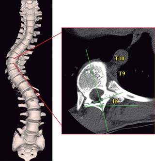
Figure 8: Axial tomography at the level of apical vertebra (T9) with 18 grades rotated towards convexity.
Pleural lining of the thoracic cavity is in contact with the inferolateral wall of the pedicle, while medially the pedicle is in contact with the dural sheath of the spinal cord and the nerve roots.12 Many studies show that neurological deficits often have medial pedicle perforation of more than 4 mm.20 All these anatomical landmarks stress the importance of detailed knowledge of the anatomy of the spine with a clear understanding of pedicle projection, however even with the use of image-guide navigation for screw placement the rate of pedicle wall perforation has been reported between 1.2 to 4.3%.17 Thus, techniques to optimize placement and guarantee intraosseous pedicle screw position have been developed to enhance safety of pedicle screw placement. First introduced by orthopedists that demonstrated their usefulness in hip and knee,23 the navigational template created by reverse engineering principle have found its application in spine surgery, as Goffin, Owen and Lu have demonstrated in cervical spine,9,24,25 particularly because of its ability to determine the orientation and size of each pedicle based on the unique morphology of each individual, and especially suited for treating abnormal vertebral. In addition, its potential advantage for operating time reduction, as well as its high accuracy in narrow pedicles, cost effectiveness and absence of radiation for patients and surgeons, we thought of introducing and probing the applicability of this technology for correction of severe deformity.
By using this novel, custom-fit sequential multilevel navigational templates in surgical correction of a complex spinal deformity case presented here, we obtained an important reduction of the scoliotic curves, no misplacement or reposition of any pedicle screw, complete elimination of radiation for surgeon but most importantly, no neurovascular complication. The sequential multilevel navigational technique could be a safe and accurate accessible technology. However, this statement requires further validation in the clinical setting with a larger sample and comparing this simple technology with other image-guide systems for pedicle screw fixation.

