SciELO - Scientific Electronic Library Online

 
vol.7 número41Gestión del Conocimiento a través de la Colaboración Horizontal en el Clúster MACHEvaluación de la contaminación por metales pesados en suelos de la Reserva Ecológica de Manglares Cayapas Mataje (REMACAM)-Ecuador índice de autoresíndice de materiabúsqueda de artículos
Home Pagelista alfabética de revistas  

Servicios Personalizados

Revista

Articulo

Indicadores

Links relacionados

  • No hay artículos similaresSimilares en SciELO

Compartir


RIIIT. Revista internacional de investigación e innovación tecnológica

versión On-line ISSN 2007-9753

RIIIT. Rev. int. investig. innov. tecnol. vol.7 no.41 Saltillo nov./dic. 2019  Epub 05-Feb-2021


Artículos

Vibrational Modal Model for a Compressor Blade

Modelo Modal Vibracional de un Álabe de Compresor

H.J. Zúñiga-Osorioa  b 

E.E. Rodríguez-Vázqueza  b  * 

L.A. Montoya-Santiyanesa 

I. Alonso-Mejíaa 

C. Sandoval-Ríosc 

a National Laboratory for Cooling Technology Research (LaNITeF), Eng. Center for Ind. Development (CIDESI), 76130, Santiago de Querétaro, Qro., México.

b School of Engineering, Anahuac University of Queretaro, 76246, Santiago de Querétaro, Qro., México.

c Research Center for Applied Science and Advanced Technology (CICATA), National Polytechnique Institute (IPN), 76090, Santiago de Querétaro, Qro., México.


Abstract

The analysis of thermodynamic machinery (cooling systems and gas turbine technologies) exposed at certain set of critical ambient conditions, is always a continuously issue for the mechanical engineering; where the state of the art statement is concerned not just with the dynamics magnitude measurement and the regulation of the process variables into the critical stages from the strategical machine systems, nowadays it also needs to observed and control the spatial distribution of the energetic variables into the volumes of interest. As a first step to address this engineering area of opportunity, and based on the hypothesis that the flow incidence in solid bodies induces energy on them as mechanical vibrations, in this work, a methodology is proposed to get a mathematical model based on the vibrations behavior from a set of blades of a gas turbine compressor; which is based on the lumped mass hypothesis. In the future, with the validation of the gotten model, authors will intend to characterize in-vivo the spatial behavior of the air flow into the ventilation systems grids and/or the flow conditioning stages (expansion or compression) from the rotating machinery, by the measuring and analyzing the vibration in these components; since this is not exposed instrumental system, neither the performance of the concerned machinery, nor the integrity of the sensor device is affected by the energy magnitude and distribution in which the flow insides. The proposed methodology consists of two stages: the first stage is a linear approximation of the model parameters for mass and stiffness from the experimental results of an experimental modal testing based on the impact test, and the second stage is a recursive adjustment of the parameters for damping to reduce the error in the estimation of the resonance frequencies and their corresponding modal shapes. The result of the computational approximation agrees with the experimental results and also by applying the concerned recursive adjustment, the maximum average error has been reduced from 28.3% to 2.5%.

Key Words: Vibrations; Experimental modal testing; Parameters identification algorithms

Resumen

Estudiar la confiabilidad bajo condiciones ambientales y de trabajo tanto de sistemas de refrigeración como de la tecnología de las turbinas de gas, es una área de mejora constante dentro de la ingeniería mecánica; donde el conocimiento de frontera concluye en la necesidad no solo de conocer y regular el comportamiento dinámico de las variables de proceso en algunas zonas estratégicas, sino también observar y controlar la distribución de dichas variables dentro de los espacios de interés. Como un primer paso para atender esta área de oportunidad, y basados en la hipótesis de que la incidencia de flujo en cuerpos solidos induce energía en estos que se representa como vibraciones mecánicas, en este trabajo por tanto, se describe una metodología propuesta para obtener un modelo matemático a partir del comportamiento vibratorio de un conjunto de álabes de un compresor de turbina, el cual se fundamenta en la hipótesis de masas concentradas. Con la validación del modelo propuesto en un futuro los autores pretenden caracterizar en vivo el comportamiento espacial flujo de aire que incide sobre rejillas de sistemas de ventilación y/o etapas de acondicionamiento (expansión o compresión) de maquinaria rotativa, mediante la medición y análisis de las vibraciones presentes en estos componentes; ya que de esta manera no se afecta ni al desempeño de la maquinaria en cuestión, ni la integridad del dispositivo sensor ante las condiciones energéticas (presión y temperatura) en las cuales los flujos llegan a presentarse. La metodología propuesta consta de dos etapas: la primera es una aproximación lineal de los parámetros de masa y rigidez a partir de los resultados experimentales de un análisis modal experimental basado en la prueba de impacto, y la segunda es un ajuste recursivo de los parámetros de amortiguamiento para disminuir el error en la estimación de las frecuencias de resonancia y de las correspondientes formas modales. El resultado de la aproximación computacional concuerda con los resultados experimentales y además aplicando un ajuste recursivo, el error máximo promedio se logra disminuir del 28.3% al 2.5%.

Palabras Clave: Vibraciones; Turbinas de gas; Análisis modal experimental

1. Introduction

The gas turbine implementation has increased because it is one of the most trustworthy technology to convert flowing energy to efficient and useful work, also with regulated contaminants emissions and moreover for its flexible operation to use gas and/or liquid fuels 1-5. Then, due to the worldwide natural gas availability and the global infrastructure for its distribution, the most viable technology to satisfy the energetic pick demand of the emergent economies like Mexico, could be the gas turbine 6-7.

The gas turbine behavior is described by means of the thermodynamic Brayton cycle which starts by the continuous confinement of a certain amount of atmospheric air. This air is compressed by a set of blades accommodated at the stator and rotor into the compressor stage. Then this air is mixed with the injected fuel and this mixture is burned into the combustion chamber; here is where the power is added and extracted from the fuel. Therefore this power concentrated gets away by its expansion through the turbine blades and consequently by moving the engine rotor 8-10.

The flow behavior through the gas turbine strongly defines this device performance; so that, it is important do not only estimate or measure punctually the flow magnitude into the different engine stages, it is needed to know the dynamic flow distribution profile also 11-12.

1.1. Current technologies for the flow analysis in gas turbines

To analyze the concerned flow distribution profile in the gas turbines, the state of the art mainly reports the implementation of four techniques: Computed Flow Dynamics (CFD), Velocimetry and Image Processing, Doppler Effect and the escalation from punctual measurements sampling.

Because of its accuracy, the CFD is the most used technique to analyze the aerodynamic profile of the compressor and turbine blades; but because of its complexity and the large amount of interactions needed for its solution, its experimental implementation online is not an option 13-14.

There is a high relationship between both techniques CFD and Velocimetry (complemented with image processing); because them both have been used to validate mutually their results for the flow distribution profile analysis in aerodynamic experiments. But again, both implementations in situ with gas turbine engines are almost impossible because of the facilities and infrastructure needed 14-15.

Several experimental set ups based on the Doppler effect have been implemented to analyze the air flow behavior in the compression and expansion stages from different engines topologies; but the implementation of these techniques in gas turbines is limited, because the Doppler effect strongly depends of the ambient and geometric conditions. Moreover, because it is not an onsite analysis 16-17.

The escalation from the punctual measurements sampling is the most used technique in the commercial gas turbines, because of the robustness and reliability of the sensors technology 18. The main disadvantage of this technique is that it is grounded on extrapolations estimation and does not give information of the real dynamic flow distribution profile 18-19.

1.2. Vibrations for the analysis of flow dynamics

Based in the hypothesis that the compression and expansion process of the air flow in the gas turbine produces spatial pressure gradients which also induces acoustic waves, it is predicted that the air flow interacts with the stator blades by inducing vibrations on them. Then, the fundamental idea of the future application for the model proposed here is to predict how to the air flow through the compressor and the turbine stages interacts with the stator blades by the vibrations induced, which by taking in account the environmental conditions (pressure and temperature) can be measured without sensors risks and also without influencing the thermodynamic behavior of the concerned engine 20-21.

Into the theoretical analysis of flows, the energy transmission, as continuous waves is fundamental if it is talking about the interaction between energy passed from flowing gases to solid and rigid bodies 22-23. Since the wave equation looks for an analytic solution of the oscillation movement, it is the most precise tool to estimate the energy distribution into the thermodynamic machinery as well as gas turbines, heat exchangers, and aerodynamics 24-26. Just because of the border conditions the wave equation solution turns simultaneously as complex as the geometry of the machinery components also does 27; therefore, several tools have been developed to analyze the energy distribution in complex geometry systems.

In the case of thermodynamic rotating machinery as well as the gas turbine technology, some authors have discretized the spatial dimension of the wave equation to analyze the vibrational energy into the engine shaft as stations; developing analysis methods as transfer function matrix 28, FEM (finite element method) 29, lumped mass 30 and experimental modal testing analysis 31.

Afterwards, the finite volume concept was implemented into the CFD (computational fluid dynamics) to analyze the energy flow into the nowadays heat interchangers from the current vapor compression cooling systems 32-33, and to the dynamic modeling of this kind of devices to implement more complex control systems.

The theoretical fundamentals of the modeling strategy of this technical proposal is based on the lumped mass hypothesis, to interpreters the energy transmitted from the air flowing to the vibration from the concerned set of blades; and its first parameters adjustment came from an experimental modal testing.

The lumped mass modeling has been implemented from at least the end of the XIX century used for the mechanical performance of structures 34-35and both passive 36 and rotating machinery 37; meanwhile thanks to the vibration sensing technology apparition, the experimental modal testing has been used to analyze the vibrational performance of several mechatronic systems 38-39.

The mathematical structure for the model proposed is a multi-node mass-damping-stiffness system which describes the vibrations of a compressor blade based on the lumped mass hypothesis 40-42. The model nodes are punctually located in the points where experimentally the free modal shapes have their higher amplitudes (previously analyzed by an oversampled experimental modal testing).

1.3. Systems dynamics modeling and recursive algorithms for the parameters identification

Into the systems dynamics engineering the mathematical modeling of systems works as a reference to identify the real systems dynamics; in this area there are at least three paradigms used for this purpose. The first paradigm is the identification of dynamic relation between the processes variables, based on the main apportion that each tangential dynamical space has into the output variables behavior that mainly defines the systems performance 43.

The most recent paradigm for the systems modeling are the smart algorithms, like: artificial neural networks, fuzzy logic, genetic algorithms and other combinations between them. This systems modeling paradigm has reported a very accurate results in terms of the dynamics predictions; but they need a big among of experimental data to get an acceptable synthonization 44.

The last systems modeling paradigm come the physical relationships in the between of the process variables, which most of the time come from energetic, mass, force or momentum equilibrium. This paradigm is the most used one, in terms of the results interpretation; so that, it is the most used for the systems design engineering 45.

This work proposal is based on this third system modeling paradigm, and the physical relationship that describe the system behavior is the force equilibrium from the mechanical vibrations. The most important scope of this work modeling is the future analysis of flow from the impact force into the vibrational structure of the rigid body in which the concerned flow is impacting.

Therefore to analyze the vibrational systems properties in terms of resonance frequency and time response, a parametric identification algorithm is needed. Reports from the state of the art conclude that the Kalman filters and its different variations are the most used algorithms for the systems identification 46, but it technological implementation is limited because of the computational resources needed.

Kalman filters and other like minimum square, can estimate the systems parameters magnitude on line in their simplest versions; but these algorithms become recursive if the parameter estimation feedback the dynamics system modeling and an acceptance criteria is achieved with an optimization methodology implementation 47.

As well as for the systems modeling, the smart algorithms have been also implemented in the systems parameters identification, but again the big amount of data needed represent also a big disadvantage of this kind of algorithms in terms of the computational resources needed 48.

Because of its simplicity, the minimum square algorithm is the one implemented in the recursive estimation of the damping coefficient of the vibrational model in which this work proposal is based. In this implementation, this algorithm is based on the error square value from the difference between the real eigenvalues and the estimated ones, then the damping matrix coefficients are corrected by considering the tangential distance between each square error interaction in terms of the precedent damping matrix components.

The free modal shapes of the concerned compressor blade were gotten from an experimental modal analysis using the impact test method. To calculate the modal model coefficients for stiffness, damping and the dynamic momentum, the damping effect was considered null for the first approximation which was performed using just linear algebra; then a recursive algorithm was implemented to diminish the calculus error for the natural frequencies. This recursive algorithm modifies the damping coefficients by considering the experimental results of the experimental modal analysis.

2. Experimental Method

Fig. 1 shows the gas turbine set of blades that was used to support experimentally this work proposal. This set of blades is from the fourth stage of the stator from an axial turbo-compressor, which is composed by 24 pieces like this. The weight of this set of blades is 0.782 kg and it is composed by forth blades with its internal and external radial junctions. In Fig. 1, it is also shown both the CCLD accelerometer (model Brüel & Kjaer type 4506) and the impact hammer (model PCB 086C03) that were used to the vibrations measurement from the executed impact tests.

Figure 1. Set of blades used for this work analysis. 

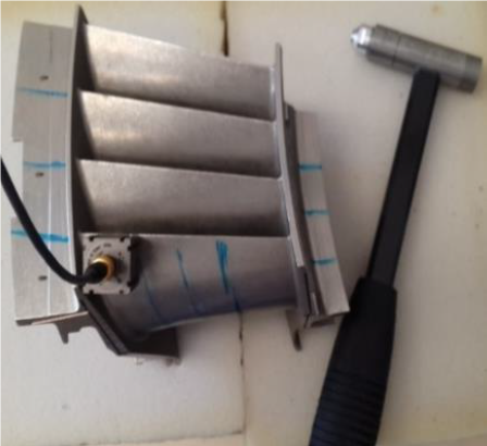
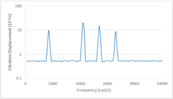
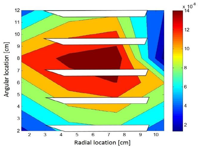
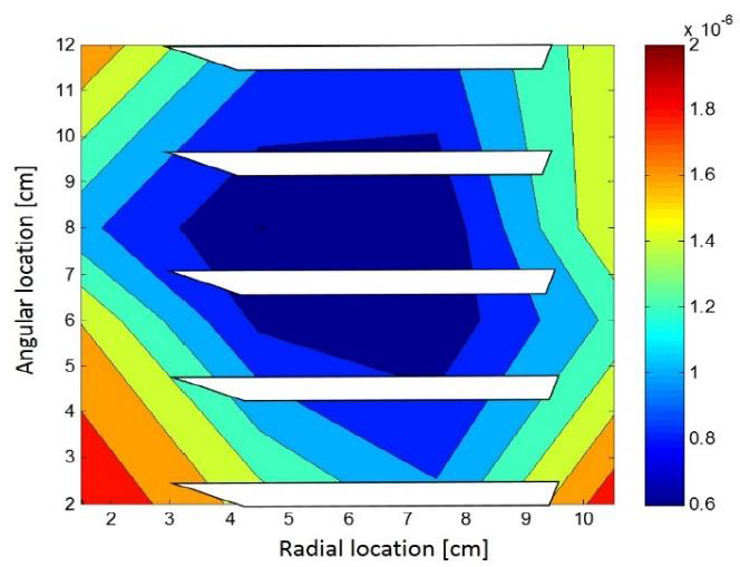
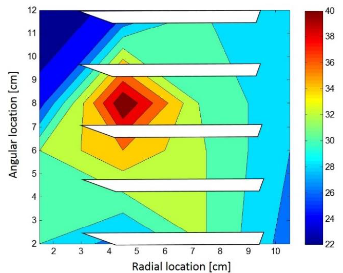
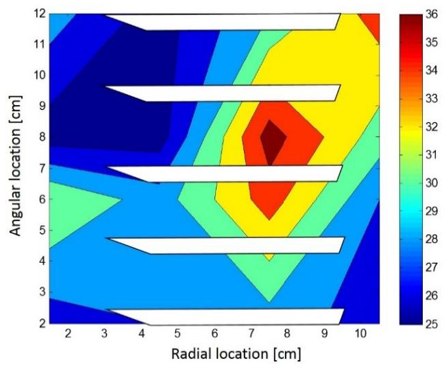
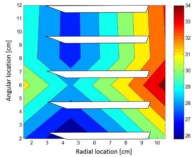
Based on the experimental spectral response of the vibration from the set of blades in the impact tests, the accelerometers were located in 16 positions along the surface of the concerned set of blades where its vibrations magnitude were higher. The impact tests were performed by following the experimental modal analysis method (roving-accelerometer and roving-hammer test) 20,24. An example of the experimental measurements for the axial vibrations are shown in Fig. 2. While Figs. 3 to 6, show the four modal shapes measured into the calibration range of the accelerometers used.

Figure 2. Vibration displacement magnitude from the experimental measurements. 

Figure 3. Amplitude in meters of experimental modal shape at 1778 [rad/s]. 

Figure 4. Amplitude in meters of experimental modal shape at 4191 [rad/s]. 

Figure 5. Amplitude in meters of experimental modal shape at 5432 [rad/s]. 

Figure 6. Amplitude in meters of experimental modal shape at 6614 [rad/s] 

3. Mathematical Model.

The measurements data shows that for the axial axis the vibrational system behavior present four resonance peaks at their frequency response (Fig. 2), so the lumped mass hypothesis needs a second order mass-damping-stiffness model with four degrees of freedom at least for each blade. Fig. 7 shows the geometrics of the mathematical proposal which has the next structure.

Mx¨t+Bx˙t+Kxt+Ft (Eq. 1)

Where:

xt=  x1,1tx1,2tx4,4 tis the displacements vector,

Ft=  F1,1tF1,2tF4,4 tis the applied forces vector,

and the dynamics matrixes are given by

M=m1,1m2,1m3,1m4,10m1,2m2,2m3,3m4,30m1,4m2,4m3,4m4,4

B=B0,1+B1,1000-B0,10-B1,1B1,1+B2,1-B2,10000-B2,1B2,1+B3,1-B3,10000-B3,1B3,1+B4,100-B0,1000B0,1+B0,2+B1,2-B1,20000-B1,2B1,2+B2,200B2,3+B3,3-B3,30000-B3,3B3,3+B4,2+B4,3000-B4,300B0,3+B1,4+B2,4-B1,40000-B1,4B1,4+B2,4-B2,40000-B2,4B2,4+B3,4-B3,40-B4,300-B3,4B3,4+B4,3

K=K0,1+K1,1000-K0,10-K1,1K1,1+K2,1-K2,10000-K2,1K2,1+K3,1-K3,10000-K3,1K3,1+K4,100-K0,1000K0,1+K0,2+K1,2-K1,20000-K1,2K1,2+K2,200K2,3+K3,3-K3,30000-K3,3K3,3+K4,2+K4,3000-K4,300K0,3+K1,4+K2,4-K1,40000-K1,4K1,4+K2,4-K2,40000-K2,4K2,4+K3,4-K3,40-K4,300-K3,4K3,4+K4,3

Figure 7. Vibrational model structure for each axis modal model. 

By converting Eq. 1 to the frequency domain we have

K-ω2Mx¨t-jωBxω=Fω (Eq. 2)

To facilitate the estimation of the mass and stiffness coefficients, the damping was taken out from Eq. 2, so it can be solved as:

K-ω2M16×16 Xω16×1=Fω16×1 (Eq. 3)

Experimentally, the impact tests were performed by inducing simultaneously a one Newton impact force at the sixteen positions (show Fig. 1), therefore the applied force vector can be considered as:

Fω=1111×16

The solution of this impact for the four resonance frequencies identified in Fig. 2, are:

K-ω12M16×16 Xω116×1=116×1K-ω22M16×16 Xω216×1=116×1K-ω32M16×16 Xω316×1=116×1K-ω42M16×16 Xω416×1=116×1 (Eq. 4)

Experimentally all resonance frequencies are known ω 1, ω 2, ω 3 and ω 4, also the modal shapes X(ω 1)16x1 (Fig. 3), X(ω 2)16x1 (Fig. 4), X(ω 3)16x1 (Fig. 5) and X(ω 4)16x1 (Fig. 6); so that, we can organize these equation as:

K-ω12M16×160000K-ω22M16×160000K-ω32M16×160000K-ω42M16×1664×64Xω116×1Xω216×1Xω316×1Xω416×164×1=116×1116×1116×1116×164×1 (Eq. 5)

and Eq. 5 can be re-organized as:

RGX,ω64×34km34×1=RX ω116×18GX ω1,ω116×16RX ω216×18GX ω2,ω216×16RX ω316×18GX ω3,ω316×16RX ω416×18GX ω4,ω416×1664×34K1,1K1,2K4,2K4,3m1,1m1,2m4,3m4,434×1=116×1116×1116×1116×164×1 (Eq. 6)

Where:

RX ωn16×18=X1,1ωnX1,1ωn-X1,2ωn00X1,2ωn-X1,1ωnX1,2ωn-X1,3ωn00X4,3ωn-X4,2ωnX4,3ωn-X4,4ωn00X4,4ωn-X4,3ωnX4,4ωn16×18,

GX ωn,ωn16×18=-ωn2X1,1 ωn00-ωn2X1,1 ωn00-ωn2X1,1 ωn00-ωn2X1,1 ωn16×18

and the parameters vector

km=K1,1K1,2K4,2K4,3m1,1m1,2m4,3m4,4

Which includes in this case the unknown eighteen stiffness parameters and the sixteen mass parameters as well.

By solving Eq. 6 for the km vector, the listed unknown parameters can be estimated as:

km34×1=RGX,ω-134×64116×1116×1116×1116×164×1 (Eq. 7)

The big issue of this first approximation is that it depends of the solution of a not-square inverse matrix [RG(X,ω)]-1 34x64, therefore it has intrinsically a considerable numerical error which comes from the mathematical algorithms of the software resolvers. Table 1 and Figs. 8, 9, 10 and 11 shows the error of this first approximation application in the dynamic model.

Table 1. Natural frequency estimation errors. 

Frequencies [rad/s] Error [%]
1 1888.0 5.8
2 3647.5 14.9
3 4945.2 9.8
4 9226.6 28.3

Figure 8. Error for the 1st modal shape [%]. 

Figure 9. Error for the 2nd modal shape [%]. 

Figure 10. Error for the 3rd modal shape [%]. 

Figure 11. Error for the 4th modal shape [%] 

4. Adjustment Algorithm

After the mass and stiffness coefficients were calculated, a recursive algorithm was implemented to diminish the errors reported on Table 1. This algorithm works by the adjusting the damping parameters and reducing the error from the output values to the experimental data of the natural frequencies, based on the two definitions of the damping coefficient:

ξ=1n-1lnxmaxxss4π2+1n-1lnxmaxxss2, (Eq. 8)

and

ξ=B2mωn, (Eq. 9)

Which corresponds to the logarithmic decrement and its formal definition respectively. Eq. 8 is calculated by considering the experimental data for the maximum value of the vibrations x max and its steady state magnitude x ss , given as each modal shape for each resonance frequency.

ξi=1/ai-1lnxi max/xiss4π2+1/ai-1lnxi max/xiss2, (Eq. 10)

Where a i, is the number of cycles that the vibration signal presents to get its steady state.

This algorithm starts with an initial value of the damping matrix, then each one is increasing as well as it is shown in the recursive algorithm listed on Fig. 12 where:

B0=2000-10-12-10000-12-10000-1200-10003-10000-12002-10000-13000-1002-10000-12-10000-12-10-100-12 (Eq. 11)

Figure 12. Recursive algorithm list for the damping parameters adjustment. 

It is the initial damping matrix, φ is the acceptation parameter for the resonance frequencies estimation, ωe 1, ωe 2, ωe 3, ωe 4 are the experimental resonance frequencies shown on Fig. 2. Table 2 and Figs. 13, 14, 15 and 16 show the final results.

Table 2. Final natural frequency estimation error after the recursive adjustment application. 

Frequencies [rad/s] Error [%]
1 1750.0 1.5
2 4105.2 2.0
3 5297.9 2.5
4 6479.7 2.0

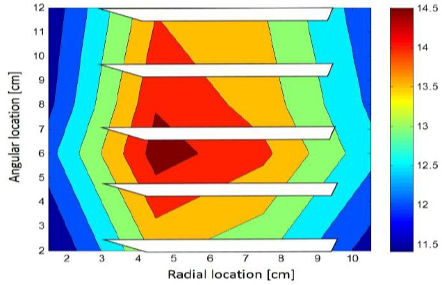
Figure 13. Error [%] for the first modal shape with the damping parameters adjusted by the recursive algorithm. 

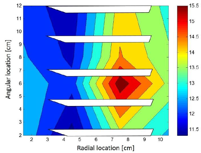
Figure 14. Error [%] for the second modal shape with the damping parameters adjusted by the recursive algorithm. 

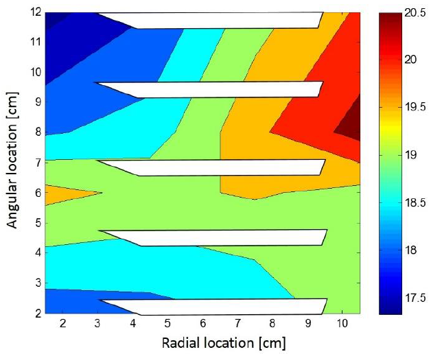
Figure 15. Error [%] for the third modal shape with the damping parameters adjusted by the recursive algorithm. 
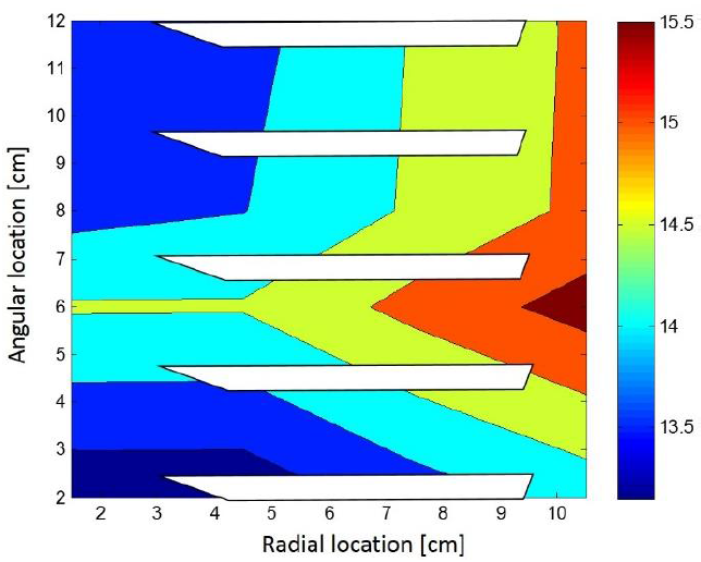
Figure 16. Error [%] for the fourth modal shape with the damping parameters adjusted by the recursive algorithm. 

5. Conclusions

The experimental modal analysis from the set of blades analyzed, was developed through a set of multi-points and simultaneous impact tests, giving four natural frequencies with their corresponding modal shapes in the frequency spectrum of interest for this study case.

Through the authors expertise and the state of the art statement the experimental vibrational modal shapes reported in this document belong to the first four flexible theoretical modes; and their spectral order presentation is also according with the vibration theory if it is considered the free body vibration analysis.

Based on the Fig. 2 and Figs. 3 to 6, it is predictable that set of blades vibrations occurs at high frequencies (1750 to 6500 Hz) with a very low amplitude (less than 14x10-6 m), then because of the rotor rotational speed (7500 rpm = 450,000 Hz) the natural frequencies are excited just in the engine start up or in its pull down; therefore, it has certain that in the steady state speed the set of blades vibrations hardly comes from the flow impacting this solid shape.

The first modal model (without damping adjustment) has a good error of 28.3%, if it is considered that the directly parameters estimation depends on the estimation of a pseudo-inverse matrix; but, to develop more accurate control algorithms the adjustment method proposed is justified, overall if nonlinearities from dynamics are considered.

The recursive algorithm for the model adjustment by modifying the damping parameters has increased the entire mathematical model accuracy to 2.5%, it does not only calculate natural frequencies, it also performs a better modal shapes estimation (see Figs. 13 to 16 and Table 2).

It is important to clarify that the magnitude of the criteria from decision taking from the average of the Eigen values error, in the sixth step of the recursive algorithm; was selected to ensure this algorithm convergence occurs in less than 200 microseconds, to avoid interference with the fastest natural frequency included.

It is concluded also that, because of the naturally of the vibration behavior from the tested set of blades reacts as an underdamped system to a hammer impulse (experimental modal testing); through the inclusion of the damping parameters to the model by the recursive algorithms its results are better than the ones from the analysis without damping consideration.

Modal shapes adjustment is not as good as the frequencies prediction is, so in a future version, the modal shapes error will also have been included into the recursive adjustment algorithm if more accuracy is required.

The validation of the theoretical fundamentals from this proposal for a vibration modal model from the compressor set of blades has been experimentally proven; furthermore, in accordance with the results gotten after the recursive algorithm implementation for the parameters adjustment, the next step for this proposal will be correlate the vibrational behavior from the concerned set of blades with the regulated air flowing in a wind tunnel, with the intention to get an instrumental systems for the air flow characterization by the indirect vibration analysis.

Acknowledgment

Authors thanks COMECYT (Mexiquense Council for Science and Technology) for the support to this work by borrowing the instrumentation system, fact that is pushed in because this model will be used for the flow analysis on the experimental setup for the “Coating process development for the valve inside by the HVOF technique” project, identified by number VINCULACION/2018/03 and developed between the Industrial de Valvulas S.A. de C.V. (Walworth México) company and the National Laboratory for Cooling Technology Research (LaNITeF) from the Engineering Center of Industrial Development (CIDESI).

Thanks are extended to CONACYT (National Council for Science and Technology) for the sponsorship through the Scholarships No. 437556, 492895 and 437556, and by the National Laboratories Program Project No. 299090 from LaNITeF. Thanks includes also to the School of Engineering of the Anahuac University of Querétaro.

References

1. Saravanamuttoo, H. I. H., Rogers, G. F. C., Cohen, H., 2001. Gas Turbine Theory, Pearson. [ Links ]

2. Layne, A.W., 2001. Next Generation Turbine Systems, IEEE Power Engineering Review, pp. 18-23, April. [ Links ]

3. Hong Lee J., Tong Seop K., Eui-hwan, K., 2017. Prediction of Power Generation Capacity of a Gas Turbine Combined Cycle Cogeneration Plant, Energy 124, pp. 187 - 197. [ Links ]

4. Pilavachi, P. A., 2000. Power Generation with Gas Turbine Systems and Combined Heat and Power, Applied Thermal Engineering 20, pp. 1421 -1429. [ Links ]

5. Claeson, U., Cornland, D., 2002. The Economics of the Combined Cycle Gas Turbine-an Experience Curve Analysis, Energy Policy 30, pp. 309-316. [ Links ]

6. Fischer, R., Serra, P., Joskow, P. L., Hogan, W. W., 2000. Regulating the Electricity Sector in Latin America, Economía, Vol. 1, No. 1, pp. 155-218, Available from http://www.jstor.org/stable/20065398. [ Links ]

7. Ruiz-Mendoza, B. J., Sheinbaum-Pardo, C., 2010. Electricity Sector Reforms in Four Latin-American Countries and their Impact on Carbon Dioxide Emissions and Renewable Energy, Energy Policy 38, pp. 6755-6766. [ Links ]

8. Yee, S. K., Milanovic, J. V., Hughes, F. M., 2008. Overview and Comparative Analysis of Gas Turbine Models for System Stability Studies, IEEE Transactions on Power Systems, Vol. 23, No. 1, February. [ Links ]

9. Poullikkas, A., 2005. An Overview of Current and Future Sustainable Gas Turbine Technologies, Renewable and Sustainable Energy Reviews 9, pp. 409-443. [ Links ]

10. Yee, S. K., Milanovic, J. V., Hughes, F. M., 2011. Validated Models for Gas Turbines Based on Thermodynamic Relationships, IEEE Transactions on Power Systems, Vol. 26, No. 1, February. [ Links ]

11. Rolland, E. O., De Domenico, F., Hochgreb, S., 2017. Theory and Application of Reverberated Direct and Indirect Noise, Journal of Fluid Mechanics, Vol. 819, pp. 435-464. [ Links ]

12. Doorly, D. J., Oldfield, M. L. G., 1985. Simulation of the Effects of Shook Wave Passing on a Turbine Rotor Blade, Journal of Engineering for Gas Turbines and Power, Vol. 107, October. [ Links ]

13. Feng, Z., Long, Z., Chen, Q., 2014. Assessment of Various CFD Models for Predicting Airflow and Pressure Drop Through Pleated Filter System, Building and Environment, Vol. 75, pp. 132-141. [ Links ]

14. Singh, R., Kumar, B.D., Kumar, S., 2015. Design and CFD Analysis of Gas Turbine Engine Chamber, International Journal of Science and Research, Vol. 4. [ Links ]

15. Grafteaux, L., Michard, M., Grosjean, n., 2001. Combining PIV, POD and Vortex Identification Algorithms for the Study of Unsteady Turbulent Swirling Flows, Measurement Science and Technology, 12, pp. 1422-1429. [ Links ]

16. Al-Hamdan, Q.Z., Ebaid, M. S. Y., 2006. Modeling and Simulation of a Gas Turbine Engine for Power Generation, Journal of Engineering for Gas Turbines and Power, Vol. 128. [ Links ]

17. Tezuka, K., Mori, M., Suzuk,i T., Kanamine, T., 2008. Ultrasonic Pulse-Doppler Flow Meter Application for Hydraulic Power Plants, Flow Measurement and Instrumentation, Vol. 19, pp. 155-62. [ Links ]

18. Conners, T.R., System and Method for Direct Non-Intrusive Measurement of Corrected Airflow, U.S. Patent 6,473,705. [ Links ]

19. Meher-Homji, C.B, Mee, T.R., 2000. Inlet Fogging of Gas Turbine Engines: Part A-Theory, Psychrometrics and Fog Generation, In ASME Turbo Expo. [ Links ]

20. Trivedi, C., Cervantes, M.J., 2017. Fluid-Structure Interactions in Francis Turbines: A perspective Review, Renewable and Sustainable Energy Reviews, pp. 87-101, 2017. [ Links ]

21. Langford, M.D., Breeze-Stringfellow, A., Guillot, S.A., Solomon, W., Wing, F. Ng., Estevadeordal, J., 2007. Experimental Investigation of the Effects of a Moving Shock Wave on Compressor Stator Flow, Journal of Turbomachinery, Vol. 129, pp. 127-35. [ Links ]

22. Fahy, F., Sound and structural vibration - radiation, transmission and response, Journal of Vibration, Acoustics, Stress, and Reliability in Design, Academic Press, 1985. [ Links ]

23. Donskoy, D., Sutin, A., Ekimov, A., Nonlinear acoustic interaction on contact interfaces and its use for nondestructive testing, NDT & E International, Vol. 34, No. 4, June 2001, pp. 231-238. [ Links ]

24. Dowling, A. P., Stow, S. R., Acoustic Analysis of Gas Turbine Combustors, Journal of Propulsion and Power, Vol. 19, No. 5, September 2003. [ Links ]

25. Piccolo, A., Numerical computation for parallel plate thermoacoustic heat exchangers in standing wave oscillatory flow, International Journal of Heat and Mass Transfer, Vol. 54, Issues 21-22, October 20122, pp. 4518-4530. [ Links ]

26. Curle, N., The influence of solid boundaries upon aerodynamic sound, Proceeding of the Royal Society A, Mathematical, Physical and Engineering Science, September 20, 1955. [ Links ]

27. Kyukchan, A., Skorodumova, E. A., Soling the diffraction problem of electromagnetic waves on objects with a complex geometry by the pattern equations method, Journal of Quantitative Spectroscopy and Radiactive Transfer, Vol. 109, No. 8, May 2008, pp. 1417 - 1429. [ Links ]

28. Anderson, B., Transfer function matrix description of decentralized fixed modes, IEEE Transactions on Automatic Control, Vol. 27, No. 6, December 1982. [ Links ]

29. Pierret, S., Multi-objective and Multi-disciplinary Optimizatoin of three-dimensional Turbomachinery Blades, 6th World Congress of Structural and Multidisciplinary Optimization, May 30, 2005. [ Links ]

30. Vance, J. M., Murphy, B.T., Tripp, H. A., Critical Speeds of Turbomachinery: Computer Predictions vs. Experimental Measurements - Part I: The Rotor Mass - Elastic Model, Journal of Vibration and Acousctics, Vol. 109, No. 1, January 1987. [ Links ]

31. Blevins, R. D., Acoustic modes of heat excharger tube bundles, Journal of Sound and Vibration, Vol. 109, No. 1, 22 August 1986, pp. 19 - 31. [ Links ]

32. Ji, M. K., Utomo, T., Woo, J., Lee, Y., Jeong, H., Chung, H., CFD investigation on the flow structure inside thermos vapor compressor, Energy, Vol. 35, No. 6, June 2010, pp. 2694-2702. [ Links ]

33. Banasiak, K., Palacz, M., Hafner, A., Bulinsky, Z., Smotka, J. Nowak, A. J., Fic, A., A CFD-based investigation of the energy performance of two-phase R744 ejector to recover the expansion work in refrigeration systems: An irreversibility analysis, International Journal of Refrigeration, Vol. 40, April 2014, pp. 328 - 337. [ Links ]

34. Reichl, K. K., Inman, D. J., Lumped Mass Model of a 1D Metastructure with Vibration Absorbers with Varying Mass, Conference Proceedings of the Society for Experimental Mechanics Series, 25 May 2019, Vol. 88, pp. 49 - 56. [ Links ]

35. R. Caicedo, J. M., Modeling the Effects of a Human Standing on a Structure Using a Closed Loop-Control Systems, Journal of Engineering Mechanics, Vol. 145, No. 5, May 2019. [ Links ]

36. Dong, C., Li,u H., Huang, T., Chetwynd, D. G., A Lumped Model for Dynamic Behavior Prediction of a Hybrid Robot for Optical Polishing, Mechanisms and Machine Science (book series), June 2019. [ Links ]

37. Palazzolo, A. B., Lin, R. R., Alexander, R. M., Kascak, A. F., Montague, J., Test and Thoery for Piezoelectric Actuator-Active Vibration Control of Rotating Machiery, Journal of Vibration and Acoustics, Vol. 113, No. 2, April 1991. [ Links ]

38. Kim, S. M., Lumped Element Modeling of a Flexible Manipulator System, IEEE/ASME Transaction on Mechatronics, Vol. 20, No. 2, April 2015. [ Links ]

39. Poignet, P., Gautier, M., Khalil, W., Pham, M. T., Modeling, simulation and control of high speed machine tools using robotics formalism, Mechatronics, Vol. 12, No. 3, April 2002, pp. 461 - 487. [ Links ]

40. Olsson, A., Stemme, g., Stemme, E., 1999. A Numerical Design Study of the Valveless Diffuser Pump Using a Lumped-Mass Model, Journal of Micromechanics and Microengineering Vol. 9. [ Links ]

41. Albizuri, J., et al, 2007. An Active System of Reduction of Vibrations in a Centerless Grinding Machine using Piezoelectric Actuators, International Journal of Machine Tools and Manufacture, Vol. 47, pp. 1607-1614. [ Links ]

42. Wei, Z., Boogaard, A., Núñez, A., Li, Z., Dollevoet, R., 2018. An Integrated Approach for Characterizing the Dynamic Behavior of the Wheel-Rail Interaction at Crossings, IEEE Transactions on Instrumentation and Measurement, 0018-9456. [ Links ]

43. Zhaojun, B., Krylov subspace techniques for reduced-order modeling of large-scale dynamical systems, Applied Numerical Mathematics, Vol. 43, Issue 1-2, October 2002, pp. 9-44. https://doi.org/10.1016/S0168-9274(02)00116-2. [ Links ]

44. Farag, W.A., Quintana, V.H., Lambert-Torres, G., A genetic-based neuro-fuzzy approach for modeling and control of dynamical systems, IEEE Transactions on Neural Networks, Vol. 9, Issue 5, September, 1998, 10.1109/72.712150 [ Links ]

45. Montoya-Santiyanes, L.A., Rodríguez-Vázquez, E.E., Zúñiga-Osorio, H.J., Mejia-Alonso, I., Oversampled Modal Approach of a Turbocharger Rotor from the Experimental Lateral Vibrations, International Journal of Acoustics and Vibrations, January 2020. [ Links ]

46. Hoshiya, M., Saito, Etsuro, Structural Identification by Extended Kalman Filter, Journal of Engineering Mechanics, Vol. 110, Issue 12, December 1984, https://doi.org/10.1061/(ASCE)0733-9399(1984)110:12(1757). [ Links ]

47. Chia, T.L., Chow, P.C., Chizeck, H.J., Recursive parameter indentification of constrained systems: an application to electrically stimulated muscle, IEEE Transactions on Biomedical Engineering, Vol. 38, Issue: 5, May, 1991, 10.1109/10.81562. [ Links ]

48. Matthew, P.H., Alwyn, H., Taylor, L.W., Hruska, D.D., Smart battery algorithm for reporting battery parameters to a external device, US Patent US5606242A, 1994. [ Links ]

Technological innovation: Dynamics performance analysis of the complex rigid bodies through their vibrational behavior.

Industrial application area: Instrumental systems, refrigeration, turbomachinery, control theory and energetic optimization

Received: June 27, 2019; Accepted: October 20, 2019

* Correspondence author: eloy.rodriguez@cidesi.edu.mx

Creative Commons License This is an open-access article distributed under the terms of the Creative Commons Attribution License