


 texto em
  Inglês (pdf)
 Artigo em XML
 Referências do artigo
 Enviar este artigo por email
 Citado por SciELO
  Similares em
SciELO
Similares em
SciELO 
 Permalink
1. Introduction
Often, laboratory-mandated tests for walls at high-temperature neglect the internal forces that arise in the elements, in a real-world setting, due to the constraints of temperature-induced thermal expansions (LI et al., 2015). This is because some standards, such as the Brazilian (ABNT, 2001), for conducting fire resistance testing on walls, load-bearing or not, recommend that the lateral edges of the analyzed sample have their movement free of restrictions, allowing them to expand laterally. However, international standards such as ISO 834-4 (1994) and BS 476 (1987), while suggesting the use of free vertical edges, allow lateral restrictions to be used, provided that this corresponds to the real situation to which the wall is subjected. More specifically, the abovementioned British standard recommends the use of vertical edge restraints if the wall sample in question is smaller than the real dimensions of the element under evaluation, or if this wall is located between robust pillars. Based on these standards and other studies, it is noted that simply neglecting the real characteristics of the walls that will be analyzed in the laboratory can significantly cause distortions in the final result. Shieids et al. (1988), for example, analyzed the different thermal deformation modes of a small-sized masonry wall model and observed that the maximum deflection for a given situation depends on the boundary conditions to which the element is subjected, this means, it varies according to the displacement restrictions in the edges of the sample. This was also observed by Nguyen and Meftah (2012), that by measuring the deformations at different points of the tested walls, obtained different deformations for different boundary conditions, evidencing the influence of the bonds on the thermal behavior of the element.
The concern about the limitations applied to the samples arises from the fact that the internal forces caused by the thermal expansion constricted in real fire situations have their effects not well explored. In a survey conducted in a building subjected to a severe fire, it was possible to observe occurrences of spalling of clay-brick faces (NAVARRO; AYALA, 2015). At the time, the elements had no structural function. Therefore arises the need to understand under which circumstances such spalling occur, by which mechanisms trigger it and what the possible consequences of this phenomenon on the behavior of the structure, when it’s about load-bearing masonry, since such constructive technique is widely used in buildings on multiple floors.
Therefore, the motivation of this work lies in the need to better understand the behavior of masonry structural walls submitted to high temperatures, previously explored in other studies such as Souza (2017), Al-Sibahy and Edwards (2013) and Ayala (2010), including the concept of internal stresses caused by the restrictions of thermal expansions, in order to understand the damage of the elements in real situations. Thus, the objective of this work is to analyze the behavior presented by small-scale masonry walls when exposed to high temperatures, axial loading and having their lateral thermal expansion restricted, in order to simulate conditions close to the reality in a fire situation.
2. Materials and methods
2.1 Materials
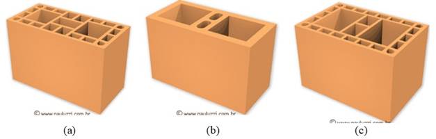
Three different types of blocks were used for this research - 7 and 10 MPa, 14 cm-thick and 7 MPa, 19 cm-thick - all made of burnt clay (Figure 1). The dimensions and other characteristics of the units are outlined in Table 1.
Table 1 Properties of the clay hollow blocks.
| ID | Characteristic Strength | Dimensions (l x h x c) | Strength of the prism (mortar fm 4 MPa) | Net area/gross area |
|---|---|---|---|---|
| B1 | 7 MPa | 14 x 19 x 29 cm | ≈ 3,5 Mpa | ≈ 0,41 |
| B2 | 10 MPa | 14 x 19 x 29 cm | ≈ 6,0 Mpa | ≈ 0,48 |
| B3 | 7 MPa | 19 x 19 x 29 cm | ≈ 3,0 Mpa | ≈ 0,36 |
Adapted from http://www.pauluzzi.com.br/produtos.php
(Fonte: <http://www.pauluzzi.com.br/produtos.php>)
Figure 1. Clay hollow blocks used. (a) B1. (b) B2. (c) B3.
Traditional prebatched mortars with resistances of 4, 6 and 10 MPa were used in the joints of the samples - according to the block employed. It was also evaluated the use of polymeric mortar for bedding the blocks, in order to assess its behavior when subjected to excessive heat and loading action, verifying the consequences for the masonry as a whole.
In one of the research stages, the samples were coated with mortar. It was used around 1 cm thick industrialized mortar as the coating material.
2.2 Experimental Program
The experimental program was carried out in three stages: in the first all three types of blocks were compared; the second evaluated the thickness and strength of the mortar of laying joints, and the presence of coating are evaluated for the same block. Finally, in the third stage, the use of polymeric mortar joints are evaluated. The details of each step are described below.
2.2.1 First stage
In the first stage, the mini-walls with three different blocks were exposed to the thermal test, with mortars strength corresponding to a maximum of 70% of the blocks characteristic compressive strengths. The mortar joints in this stage were made with a thickness of 10 ± 3 mm, filled with the mortars specified in Table 2, both vertically and horizontally, the samples had no type of coating whatsoever.
2.2.2 Second stage
In the second stage, only the brick B1, 14 cm thick and 7 MPa, was used. In this stage, the thickness of the joints, the mortar used in the samples’ execution and the presence of coating were evaluated.
In one case (P4), the bed joint was reduced to 5 mm thick, maintaining the compressive strength of the mortar at 4 MPa. Successively, the compressive strength was increased to 10 MPa, with the joint thickness maintained at 10 mm (P5).
Finally, one last situation was imposed at this stage: the coating application. In a sample made with the same characteristics as P1, a 10 mm thick layer of mortar coating was applied. Such coating was applied only on the face exposed to fire, so as not to impair the positioning of the instrumentation on the opposite face.
Thus, three more wall configurations were tested and compared to samples P1, as shown in Table 3.
2.2.3 Third stage
For this stage, the tests evaluated the samples constructed with polymeric mortar joints, compared with those constructed with traditional mortar. In the construction of these walls, the 10 MPa (B2) brick was used to facilitate the application of the polymeric mortar, as they have solid webs. Thus, the comparison was made in relation to the P2 walls, since they were made with the same structural bricks. The sample characteristics are presented in Table 4.
It is relevant that even though usually the head joints of masonry built with polymeric mortar are open, for this research, the polymeric mortar was also applied vertically, aiming to maintain the tightness of the samples against the action of high temperatures and ensure the safety during the test.
2.3 Small-scale Walls
The walls were constructed with the blocks and mortars as specified in item 2.1 and with dimensions of 90 x 80 cm, due to the oven size restrictions; therefore, they were called mini-walls. These were built on a metal profile, with a U-shape folded plate, in order to facilitate its movement. For the loads to be applied and distributed equally along the wall, the samples were covered with cement-rich mortar in the top and both sides, thus obtaining a flat surface.
The samples were cured for at least 56 days so that the moisture present in the mortar was reduced and the results would not be affected due effects present only at the initial ages. Likewise, in the samples that were coated, it was performed after at least 7 days from the construction of the walls, and the tests were performed at least after 56 days.
The samples were accommodated for testing within a loading gantry designed to withstand the applied stresses and prevent lateral expansions. It was also been designed to allow the application of distributed vertical loads in order to simulate the loading of a load-bearing wall. It is a frame made of rail tracks with two hydraulic jacks attached to it: one for vertical loading application and one for lateral confinement. Both hydraulic jacks were attached to strain gages to monitor the increments. The effort made by hydraulic jacks was distributed on wall faces using metallic profiles. The schematic drawing of the planned and assembled equipment can be seen in Figure 2.
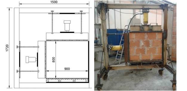
Once the sample was placed in the reaction frame, it was coupled to a Sanchis electrical resistance furnace, in this way one of the mini-wall faces was subjected to heating. The instrumentation monitoring for temperature and displacement was placed onto the unexposed face.
The load applied to the samples was estimated so they were applied in accordance with the requirements of NBR 6120 - Loads for the calculation of building structures (ABNT, 1980). Thus, loading of 97.83 kN/m was applied to the sample before starting the fire resistance test, increasing due to expansion attempts after the beginning of the test
2.4 Temperatures
Due to the limitations of the equipment available in the laboratory, the test required by NBR 5628 (ABNT, 2001) was adapted for small-scale walls that fit the available furnace size. The furnace temperature was increased to a rate like the standard curve described by the NBR 5628 (ABNT, 2001), to a maximum of 950°C, the temperature usually reached during a real fire. The mini-walls were then kept exposed to such temperature for about 4 hours.
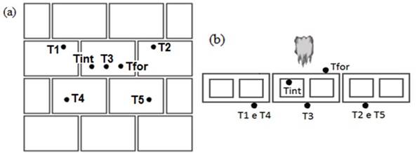
To verify the integrity of the samples, the cotton pad test was performed whenever necessary, as described by NBR 5628 (ABNT, 2001). Thermal insulation was verified using thermocouples with copper disc tip to measure the temperature on the unexposed face of the samples, as recommended by NBR 5628 (ABNT, 2001). In addition to the thermocouples placed on the non-heated face, K-type thermocouples were placed through the wall to obtain temperature values inside the oven and inside the blocks. In total seven thermocouples were distributed, five of them on the unexposed face, for thermal insulation control, and the others to collect additional information (Figure 3).
2.5 Longitudinal Displacements
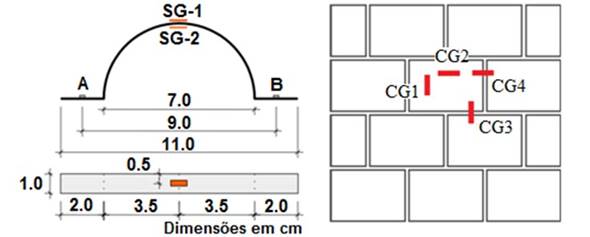
Using displacement transducers, also called clip-gages, positioned on the unexposed face of a unit in the center of the mini-walls, the horizontal and vertical deformations were measured during the hearing test. These devices were built based on those used by Beber (2003), and consist of arches with extensometers on their lower and upper faces (Figure 4). These arcs are attached to the surface whose displacements are to be measured. The specific strain determined by the strain gauges in the central section of the arcs is correlated to the relative displacements between the fixed points A and B.
The spacing or approximation between different blocks of the same course and consecutive course was also measured using clip-gages in the joints, which provides an indication of the mortar absorption of the displacements caused by thermal deformation. The positioning of clip-gages in the samples is outlined in Figure 4.
2.6 Thermography
Thermographic analysis of the samples was also conducted during its exposure to heat treatment. The use of this technique allowed the mapping of the temperature along the surface of the samples, using a FLIR T440 thermographic camera for the detection of the infrared radiation emitted by the samples when submitted to the heat. With this equipment, it was possible to monitor the temperature increase throughout the test and identify zones of possible failures in the masonry. It also rendered it possible to make a comparison of the heat spread in the different types of masonry.
3. Results and discussion
3.1 The temperature throughout the samples
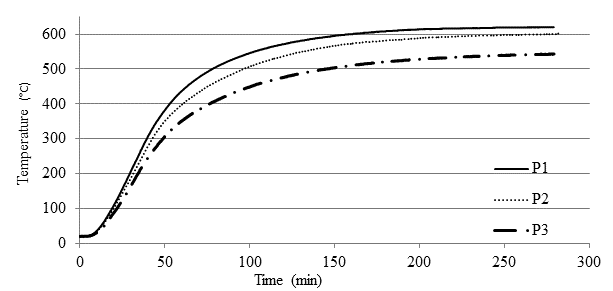
In Figure 5 is possible to see the temperature evolution inside the bricks (Tint) for the first three wall configurations, intending to compare the three different blocks. For blocks B1 and B2, the results for the intermediate thermocouple peaked around 600ºC. The wall P3 presented values below 600ºC, which was due to the fact that it was built with block B3, wider than the others.
When comparing the samples from the second stage, it can be seen from Figure 6 that the thickness of the joints and the strength of their mortars do not influence heat transfer, with the walls P1, P4 and P5 having temperatures inside the blocks around 600°C, although by adding a coating on the exposed face the temperature reduction is significant, reaching less than 400°C, for the P6 wall.
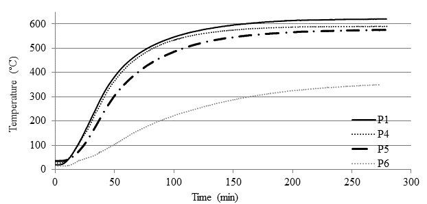
Figure 6 Temperature inside the masonry with respect to the different laying joints and coating (Group 2).
The third group of samples indicates the non-influence of the joint type on the heat transfer along the wall thickness since the results for the thermocouple readings internal to the wall blocks P2 and P7 were very similar (Figure 7). The use of polymeric mortar, therefore, offers no harm or benefit regarding this item.
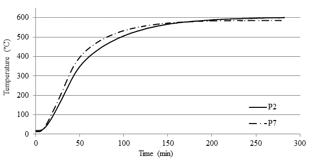
Figure 7 Temperature inside the masonry with respect to the different laying joints with traditional mortar and polymeric mortar (Group 3).
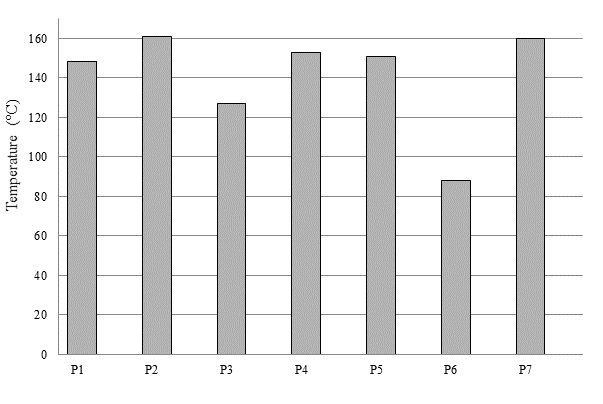
The maximum temperatures recorded on the non-heated face are represented in Figure 8. The values, in general, remained around 140 to 160ºC. The exceptions are sample P3, made with the thickest brick (B3), and P6, which had a coating on its exposed face. The latter-maintained temperatures below 90ºC, again demonstrating the insulation that the coating provides to the element, even if applied only on one of its faces. These results corroborate the data obtained by Nguyen e Meftah (2012) and Souza (2017), who found similar results with significantly lower temperatures in masonry with coated faces. The former also identified some influence of the increase of block thickness on the thermal insulation of masonry. As expected, block strengths and laying joints have no significant influence on the temperature results of the tested masonry.
Regarding the fulfillment of the criteria established by the Brazilian standard NBR 14432 (2001b), none of the samples failed to achieve the required criteria for fire-resistance rating during exposure to the test - integrity, thermal insulation, and load-bearing capacity.
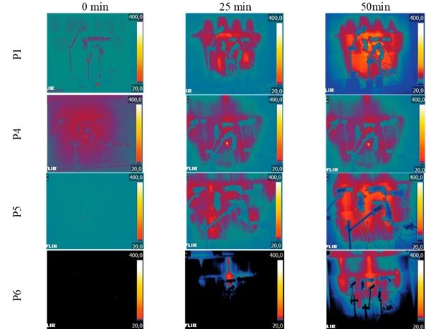
3.2 Thermographic images
Thermographic images captured every 25 minutes until the first 50 minutes of the test were selected (Figure 9 to Figure 11). The analyses were performed with a comparative purpose between the masonry samples. In the thermographic images, the lighter tone regions represent the highest temperatures.
It was possible, through the images, to ratify the best thermal insulation of the samples with the 19 cm thick block (P3) and with coating on the exposed face (P6).
For the heated sample with a coated face, the heating of the unexposed region was delayed and softened. It is possible to see in the 25-minute capture of Figure 11, however, the higher temperature spots in the upper portion. This is attributed to local cracking and spalling of the coating mortar, which allowed for great heat propagation in these regions.
The difference in color and therefore in the temperature that can be seen between the first images (time 0 min) of each figure is referred to the different room temperatures on the days of the tests, which vary greatly throughout the year in the region where the tests were performed.
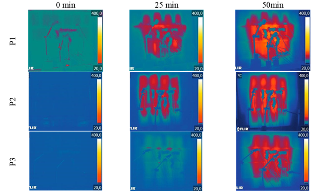
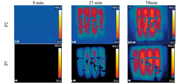
A different heating pattern can be also visualized for samples P2 and P7, made with type B2 bricks, of 10 MPa resistance, where the temperature propagates essentially through the cavities (Figure 11). The pattern is like that observed by Nguyen e Meftah (2012), who identified higher temperatures in the alveoli of the blocks. According to the authors, the main heat transfer mechanisms in a wall are convection and radiation, thus, the temperatures measured in the block cavities are higher than those measured in their transverse webs, where heat is propagated by conduction. Therefore, the observed pattern is because the webs of the B2 units are massive and, consequently, the heat propagation is smaller in these regions than in the hollow web bricks.
3.3 Longitudinal Displacement
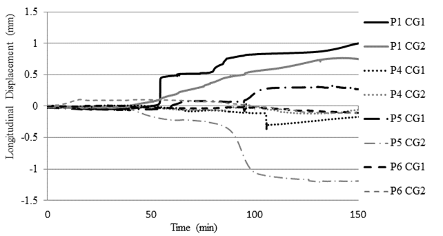
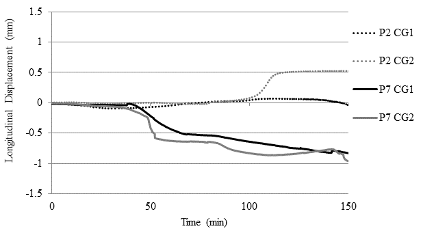
The displacements presented in this item deal with the movements within the plane of the walls. The dilatations or contractions of the bricks in the vertical and horizontal directions - CG 1 and CG 2, respectively, were measured, as well as the crushing or spacing of the masonry joints, also vertically (CG3) and horizontally (CG4).
To analyze the results the data obtained in the first 150 minutes of exposure were considered. After this point, they could suffer temperature interference, since, at this time of the test, the heating of the unexposed face reached approximately its maximum, also heating the clip-gages used in the instrumentation. The negative values in the graphs represent the closure of the displacement transducers, while positive values indicate their opening.
One of the observations that can be made from the results presented is that samples with more flexible joints tend to allow the block to dilate, forming a more deformable system compared to the others. This behavior can be observed in sample P1, where the transducers fixed to the central block - CG 1 and CG 2 - showed behavior indicating expansion in both directions (Figure 12). The onset of dilation coincides with the moment when the temperature on the outer surface begins to rise.
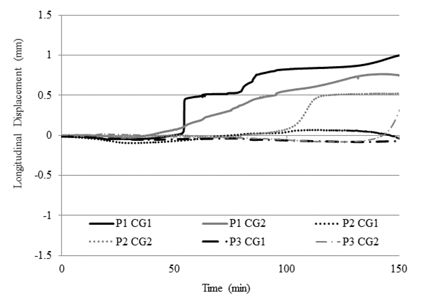
Although for sample P2 the mortar had a slightly higher resistance than that of the previous ones, the block expansion did not have the same behavior. This may have been because the lateral restraint was more effective, or because of the greater rigidity of the brick, which has massive webs, not hollow, in order to give it greater resistance. In the case of sample P3, the block practically showed no movement during the period considered. This behavior was attributed to the better thermal insulation observed for this sample, which showed little temperature increase in the early periods, thus suffering less thermal movement. The same is true for sample P6, which has better thermal insulation due to the coating of its face.
By improving the joint mortar strength to the point where it reaches or even exceeds the brick strength, as in the case of P5, the joint no longer absorbs the deformations, thus transferring compressive stresses to the brick, denoted by negative values of CG2 (Figure 13). The same is true for the sample with polymeric mortar (P7), which, because it has low deformation, also transfers stresses to the brick, causing it to be compressed in both directions - CG1 and CG2 (Figure 14).
These compressive stress transfers to the brick may indicate a warning signal for the possible occurrence of spalling in masonry when executed with high strength mortar. In sample P7, for example, jointed with polymeric mortar, it was possible to visualize in the brick a significant crack, even though it was a case of a unit with massive webs. This crack may be related to the compressive stresses existing in it.
Although the occurrence of spalling was not observed in the tests performed, it’s a beginning to better understand the characteristics that could facilitate this phenomenon in real-sized walls, as observed in the studies by Nguyen e Meftah (2012) and Souza (2017).
For almost every case, the bed joint, monitored by CG 3, shown a closure, that signal compression in the joint (Figure 15 e Figure 16). Such manifestation can be due either by the vertical loading applied to the sample, or by the expansion of the bricks adjacent to it, or by a combination of both. The exception to this pattern occurred in sample P7, where the bed joint initially behaves like the others, showing compression, and later reverses its movement, denoting joint opening (Figure 17). This fact may be caused by the degradation and loss of mortar resistance on the inner face of the wall.
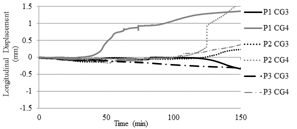

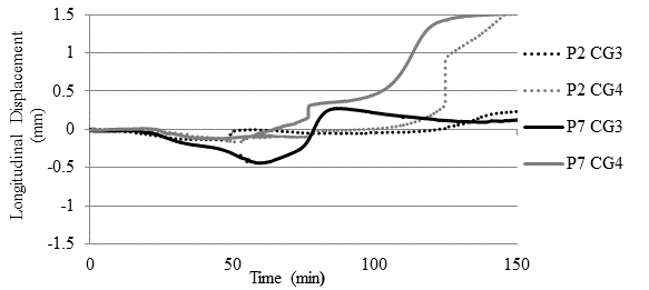
The opening movement noted on CG 4, which was manifested for most results, may have been the result of a movement of the wall as a whole, which could be expanding laterally due to an inefficient restriction in that direction. It is possible that the mortar used for capping the samples did not offer sufficient strength to prevent deformation. Thus, the crushing effect of the joint between the blocks is best visualized in the vertical direction by clip-gage 3, since in this direction the load application makes the restriction more effective.
In general, the results presented here constitute an important contribution to the development of the research regarding the mechanical behavior of masonry exposed to high temperatures, as well as contribute to the knowledge about the influence of the types of materials used in the masonry construction on the obtained results, subjects classified as scarce or absent in the study by Russo e Sciarretta (2013).
4. Conclusions
The tested walls showed good performance facing the action of high temperatures. They presented predominantly vertical cracks after exposure, especially on the face exposed to the heat. The masonry laying mortar had a significant strength loss. In the coated samples, the coating mortar completely detached from the substrate as the temperature increased.
It was possible to infer that the increase of block thickness and, above all, the use of mortar coating attenuate the heat transfer to the unexposed face.
Analysis of the data obtained for longitudinal displacements indicated that more flexible joints form a more deformable system compared to the others, allowing the brick to dilate in both directions in the plane. The increase of the mortar strength so it equals or exceeds the strength of the masonry units may pose a risk to the elements, as stress absorption by the joints is reduced thus transferring stresses to the block. The same applies to polymeric mortar due to its low deformability.
With the data obtained it is possible to observe many variables that can influence the behavior of masonry elements, being this a construction method with properties hard to comprehend in a fire situation. It is noteworthy that the scale of the studied samples, being reduced compared to reality, attribute greater rigidity to them, which certainly influences the mechanical behavior of the elements.

