


 nueva página del texto (beta)
 Inglés (pdf)
 Artículo en XML
 Referencias del artículo
 Enviar artículo por email
 Citado por SciELO
  Similares en
SciELO
Similares en
SciELO 
 Permalink
1. INTRODUCTION
Since the use of reinforced concrete in the nineteenth century in the field of construction, this material has shown great performance and durability, even when exposed to different levels of corrosive aggressiveness (Castañeda et al., 2018; Howland, 2012; Vera et al., 2009). The first time a concrete plant was installed in Cuba was in June 1895, making Havana the first city in Latin America to manufacture Portland cement concrete (Toraya, 2001).
Despite this national technological advancement, many of the buildings erected with reinforced concrete showed poor performance and the need for recurrent repair actions. This was largely due to the lack of knowledge about the negative effect of the use of unwashed sea sand in the preparation of the concrete mix, inefficient urban planning, changes in use, modernizations and erroneous estimates of environmental effects. As a consequence, many buildings reached the service life or the residual life in the first 50 years of operation (Castro-Borges and Helene, 2007; Howland, 2012). The damages caused by the corrosion of reinforcing steels due to the entry of chlorides, sulfates or carbonation of concrete have been deeply studied by several researchers in different regions of the world (Andrade and Dal Molin, 2000; Castañeda et al., 2012; Chávez et al., 2013; Helene and Castro-Borges, 2009), where the significant loss of the bearing capacity of the affected structural element has been demonstrated.
Once the material detachments begin due to the corrosion stresses of the reinforcement bars and the loss of adhesion, the risks to the life of the property's residents also appear, and repair and maintenance costs are drastically increased (Castañeda and Rodriguez, 2014). The deepening of knowledge of these aspects is the key to the design and execution of durable structures, as well as the rational rehabilitation of them (Costa and Appleton, 2002).
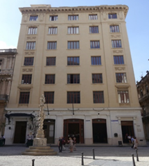
This paper aims to discuss the results of the diagnosis made to a reinforced concrete building erected between 1900 and 1906 for the firm Casteleiro & Vizoso (Figure 1). Eclectic style and seven levels high, it was projected so that all levels had 4 m high struts, except for the ground floor with 6.3 m. The building was erected on a steel structure, covered in hydraulic concrete with foundations and reinforced concrete roof. The foundations consisted of support rafts calculated to support an average load of 3 Kg/cm2. The concrete prepared to form all the midlevel and stairs was dosed in proportion to 1 volume of cement, 3 of sand and 5 of gravel. The calculation of the accidental load of the floors was estimated for 366 Kg/m2 and a safety factor of 4 was applied to the metal structure.
The property is located two kilometers away from the bay of Havana and less than 50 m from the Avenida del Puerto, in an urban-coastal environment. Since its construction and until today it has had different uses, the first being a commercial building for the firm's negotiations. After 1960 it became a post office, sometime after school and finally for two decades, real estate for renting apartments to foreign investors. To meet the needs of modern times, the hydraulic system was updated by installing a hot water line in each apartment, in the kitchen and bathroom areas.
2. RESEARCH METHODOLOGY
2.1 Research procedure
For the selection of the diagnostic tests to be used, a two-stage research methodology was applied (Geocisa, 2002). The first one aims to carry out a detailed photographic survey of each of the visible lesions, and the second one of an experimental type, based on the analysis of the organoleptic results obtained and conclusions reached in the first stage (Oroza and Bouza, 2015).
The corrosion assessment was carried out according to the standard procedure described by (NACE SP0390, 2009) which sets out as fundamental objectives the definition of the nature of the environment in which the structure is located, the inspection of physical conditions, the establishment of the extension , the nature of the corrosion and the historical data of the present structure.
2.2 Corrosion potential (Ecorr)
The method of evaluating corrosion by means of the half-cell potential is a technique that allows measuring the possible corrosive activity from the Ecorr value obtained, however it does not offer information about the kinetics of the process or the resulting icorr (Yu et al., 2017). When Ecorr <350 mV vs. CSE, indicates that there is a probability greater than 90% of active corrosion on that the rebar. On the contrary, if the Ecorr > -250 mV vs. CSE, the probability is less than 10% (ASTM C876, 2009). The equipment used for the measurements was Proceq Canin+. For the application of the potential map on the slabs, work areas of 2x2 m were established and the fixed grid was 50x50 cm.
2.3 Measurement of apparent resistivity (ρ) of concrete
To estimate the risk of corrosion presented by reinforcing steels, the Proceq Resipod equipment was used, which works based on the Wenner method (Gowers and Millard, 1999). This technique consists in evaluating the risk of corrosion presented by reinforcing bars depending on the level of saturation of the concrete pores. It is closely related to the quality of concrete (microstructure, water/cement ratio, porosity, curing, compressive strength), and therefore its durability (Andrade and D’Andrea, 2011; Azarsa and Gupta, 2017; D'Andréa and Andrade, 2009; Sanchez et al., 2017). The equipment works by applying a current on the surface of the material through the two external probes, measuring the resulting potential between the interior probes. The moisture content (water or water vapor) present in the pores of the concrete can transport the current between the probes, which makes it possible to obtain the resistivity of the material, as well as calculate the corrosion rate (icorr). Surface preparation and measurements were executed according to the manufacturer's instructions. To avoid interference in the reading due to the effect of the bars (Presuel Moreno et al., 2009), they were located and identified using a Proceq Profoscope rebar detector. For the evaluation of the icorr, the equation proposed by RILEM was applied (Andrade and Alonso, 2004) where:
2.4 Extraction of concrete probes
In order to know the compressive strength (Rc) of the concrete of the slabs, concrete probes were extracted at all levels. The equipment used was a Hilti DD-160E and a concrete press model Controls Automax 5 of 2000 KN was used. Five concrete probes were extracted per level for a total of 35.
2.5 Chemical assays of chloride and sulfate
Eight samples were extracted in the reinforced concrete slabs of each level, except for the ground floor, for a total of 48 samples. The method used for sample extractions was the indicated by ASTM C-1152 (C1152/C1152M-04, 2004). The chemical analysis procedure used was in accordance to (Oroza et al., 2016).
3. RESULTS
3.1 Diagnostic of reinforced concrete slabs
3.1.1 Results of the visual inspection
Slabs with loss of concrete coating, exposed steels and longitudinal cracks in the direction of reinforcement bars were identified (Figure 2a). The roof slab of the seventh level, in addition to the previously indicated lesions, efflorescence and leaching spots were detected due to rainwater seepage from the roof.
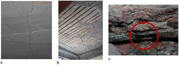
Figure 2 Damages identified in the roof slabs. a) Longitudinal cracks in the direction of the steel bars resulting from corrosion. b) Loss of repair mortar on the ceiling slabs in large areas of the living room. c) Localized corrosion at reinforcement bar
On the ceiling of all the apartments it was observed that the slabs had been previously repaired. The material used for the restoration was a cement-based structural mortar. During the inspection it was possible to verify that in these previous repairs, the original slab thickness was never recovered. Also, no anticorrosive treatment was applied to the reinforcing steel bars and as a consequence, most of the applied restoration mortar already showed cracks, slapping and loosening in various areas (Figure 2b)
The most affected spaces were those destined for cooking and bathing due to the steam generated by to the use of hot water. The reinforcement steels in the slabs of these areas had severe atmospheric corrosion effects. Some of the existing bars were found fractured or with a very advanced localized section loss (Figure 2c), jeopardizing the structural stability of the element due to possible flexural failure. The measured carbonation depth ranged between 5-6 cm, with a calculated Kco2 of 5.2 mm/year. The coating thicknesses (ec) were within 1-2 cm.
3.1.2 Results of the diagnostics assays
Based on the results of the visual assessment, two areas with different lesion manifestations were identified. One located in the first axes destined to hall and bedrooms, and another to the bottom with bathrooms and kitchens. The use of hot water in these areas increases the humidity of the environment and produces condensation of the steam on the surface of the concrete slabs. As a consequence of the increase of the water content in the concrete mass, the transport mechanisms and ionic mobility between the capillary pores are increased, accelerating the corrosion of the steel reinforcements of the slabs. To assess the risk of corrosion of the bars, Ecorr measurements were made, potential maps were constructed and the ρ was measured in each zone separately. Figures 3 and 4 show the Ecorr mapping obtained in the third level, as well as Figures 5 and 6 show the levels of ρ corresponding to the spaces prepared for Ecorr measurements.
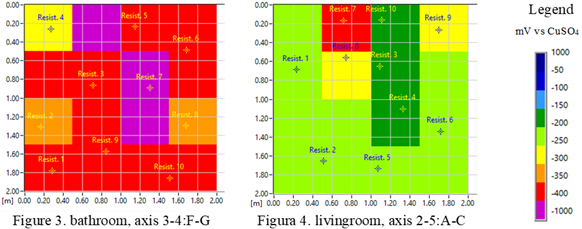
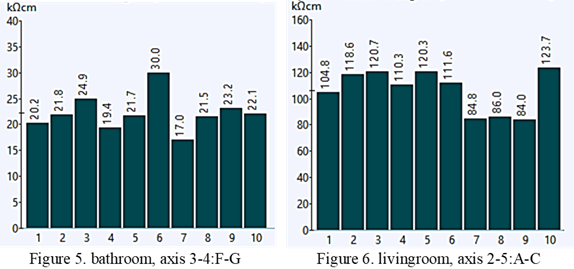
Figure 5 and figure 6. Results of the apparent resistivity on the reinforced concrete slabs of the third level
The results between both techniques demonstrate that there is a correspondence between the values of Ecorr and ρ. In areas with hot water use, the diffusion of oxygen is increased, as well as its availability at the level of reinforcements. In reinforced concrete elements where there is no primary protection due to the advance of carbonation and the presence of chloride salts, the established corrosion rate (icorr) becomes the main parameter that determines the reason for deterioration of the structure. In the drier areas, more positive Ecorr values are recorded with resistivity levels greater than 80 KΩ-cm.
Table 1 shows the average results obtained where the resistivity, icorr and chemical tests are correlated to the concrete samples, at each level of the property.
Table 1 Resume of the average results obtained by levels
| Nivel | ρ
(KΩ-cm) |
icorr
(µA/cm2) |
Cl-
(% weight of concrete) |
SO4
(mg/L) |
|---|---|---|---|---|
| 2do | 17,0 | 1,76 | 0.11 | <100 |
| 3ro | 21,1 | 1,42 | 0.12 | 107 |
| 4to | 36.7 | 0,82 | 0.14 | <100 |
| 5to | 30.1 | 1,00 | 0.11 | 118 |
| 6to | 43.2 | 0,69 | 0.12 | <100 |
| 7mo | 12.6 | 2,38 | 0.13 | <100 |
The lowest values of ρ were obtained in the 7th level roof slab as a result of rainwater leakage. This leads to the roof slab being exposed to wet-drying cycles, with leaching processes that decrease the alkalinity of the material and increase the porosity. This result in icorr values greater than 2 µA/cm2.
The chemical analysis of the concrete samples reflects a high concentration of Cl- ions, which is in correspondence with the ρ and icorr obtained at each level. The use of unwashed sea sand was a common practice in the buildings of the first half of the 20th century, where the negative effect of this anion on reinforcing steel was yet unknown. In relation to the SO4 concentrations obtained, these are not sufficient to promote a significant formation of late etringite capable of causing cracks in the concrete (Howland, 2012).
To determine the section losses of the steel reinforcements in the slabs, measurements were made at all levels. The reinforcement was discovered by removing the concrete coating between 5-8 bars per work area. As an example, the values obtained in the 5th level are shown in Table 2. All the main steels found were of 16 mm square section (crooked squares) with a nominal area of 256 mm2 and spaced between 12-16 cm. The second layer of steels are of square section of 10 mm.
Table 2 Loss section values measured in the 5th level
| Location | Bar
No. |
Measured side (mm) |
Residual area (mm²) |
Nominal side (mm) |
Nominal area (mm²) |
Section loss (%) |
|---|---|---|---|---|---|---|
| Living room | 1 | 14,15 | 200,22 | 16,00 | 256,00 | 21,8 |
| 2 | 15,04 | 226,20 | 11,6 | |||
| 3 | 14,38 | 206,78 | 19,2 | |||
| 4 | 15,28 | 233,48 | 8,8 | |||
| 5 | 15,17 | 230,13 | 10,1 | |||
| 6 | 15,1 | 228,01 | 10,9 | |||
| 7 | 14,9 | 222,01 | 13,3 | |||
| 8 | 14,67 | 215,21 | 15,9 | |||
| Kitchen | 1 | 1,73 | 2,99 | 98,8 | ||
| 2 | 7,62 | 58,06 | 77,3 | |||
| 3 | 2,61 | 6,81 | 97,3 | |||
| 4 | 7,03 | 49,42 | 80,7 | |||
| Bathroom | 1 | 12,13 | 147,14 | 42,5 | ||
| 2 | 12,4 | 153,76 | 39,9 | |||
| 3 | 12,6 | 158,76 | 38,0 | |||
| 4 | 11,9 | 141,61 | 44,7 | |||
| 5 | 11,6 | 134,56 | 47,4 |
The greatest losses of steel were registered in the spaces destined for kitchen and bathroom. The result obtained is the decrease in section in some bars of up to 99% in the kitchen area, close to the location of the water heater. In the rest of the areas of the apartments, although the measurements of ρ and Ecorr show a more “dry” material, the amount of steel losses ranges between 10-20%, being necessary a structural recalculation, to assess the feasibility in terms of replacement or splicing of new steel bars in their repair. The respective recalculation is not part of this work. However, the structure in question is rigidly framed, with columns made with I-sections where in specific cases there columns with an additional reinforcement of ordinary steel and other columns with complete reinforcement of ordinary steel are. This structure is covered with concrete, which protects the steel that forms them. The slabs are reinforced with ordinary steel bars and they support the loads of use, as well as their own weight and are transmitted to the structure provided, so it is inferred that the work is done by both elements. The results obtained proved that the current strength of the concrete is very affected.
In reinforced concrete structures, damages (cracks and fissures) caused by the phenomenon of atmospheric corrosion of reinforcing steel, chemical transformations caused by carbonation, chlorides and years of exposure, significantly influence the strength of concrete. Additionally, the charges that have acted during the lifetime of the property, which also cause a decrease in the Rc due to a phenomenon similar to relaxation, known as the Rüsch effect, should be considered (Couto et al., 2015). The results of the concrete witnesses extracted in the slabs are shown in Table 3. The highest strengths obtained were at the 5th level with average values of 8.71 MPa. The standard (ACI:562M-16, 2016) establishes as an evaluation tool that the reinforced concrete elements constructed between 1900-1919 should have a compressive strength between 7-14 MPa. This criterion is still met in the building for almost all levels, except for the third and fourth which may be due to some of the causes previously discussed.
Table 3 Average values of Rc from the concrete samples extracted from the slabs.
| Levels | Rc (MPa) |
|---|---|
| 2do | 7.40 |
| 3ro | 4.11 |
| 4to | 6.91 |
| 5to | 8.71 |
| 6to | 8,03 |
| 7mo | 7.13 |
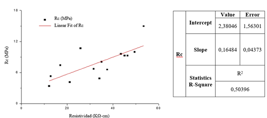
Other authors (Ramezanianpour et al., 2011) demonstrated that for the same cement mix design, there is a linear relationship between compressive strength and ρ due to the chemical similarity of the pore solution. To assess the correspondence between the concrete permeability of reinforced concrete slabs and the ρ measured directly on the slabs, both results were correlated based on the strengths of the extracted probes. Figure 7 shows the graph obtained regarding the correlation between the Rc and ρ for the mid-level slabs of the studied property.
As a summary of the measurements in the slabs, the following table is presented:
Table 4 Summary of the results obtained by levels
| Level | ρ
(KΩ-cm) |
icorr
(µA/cm2) |
Cl- (%weight of concrete) |
SO4
(mg/L) |
Rc
(MPa) |
Bars
diameter (AP- main bar AT- second layer bar) |
Section loss (%) |
Main
bar spacing (cm) |
|---|---|---|---|---|---|---|---|---|
| 2nd | 17,0 | 1,76 | 0.11 | <100 | 7.40 | AP- Ø16 AT- Ø10 |
42.9 | 12-16 |
| 3th | 21,1 | 1,42 | 0.12 | 107 | 4.11 | 25.1 | ||
| 4th | 36.7 | 0,82 | 0.14 | <100 | 6.91 | 27.7 | ||
| 5th | 30.1 | 1,00 | 0.11 | 118 | 8.71 | 45.1 | ||
| 6th | 43.2 | 0,69 | 0.12 | <100 | 8.03 | 30.2 | ||
| 7th | 12.6 | 2,38 | 0.13 | <100 | 7.13 | 65.1 |
3.2 Damages present in columns
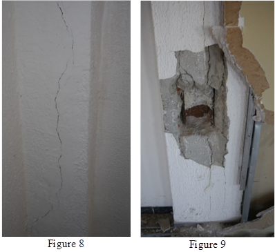
The visual inspection was carried out in the columns located in the last, penultimate and intermediate corridor. For the construction of the columns, I-sections and Ø16 steel bars were used interchangeably. It was identified that the vast majority of these had been previously intervened and still have a state of deterioration marked mainly by longitudinal cracks (Figures 8 and 9), as a consequence of the corrosion of the reinforcements. In general, both the I-sections and the bars that make up the columns showed a high level of corrosion with loss of section.
In the particular case of the second level, a high degree of corrosion with loss of section in the different reinforcements of the columns was widely observed. All the elements studied are made up of type I profiles. The coves were made in the columns indicated in Figure 10. Next, in table 5 the numbers of the coves made, and the measured wing thicknesses are presented.
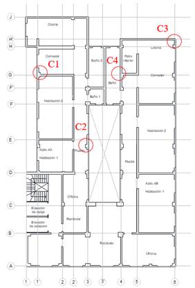
Table 5 Specifications of the coves made in columns.
| Coves | Axis | Location | Measurement (mm) |
|---|---|---|---|
| C1 | 1´:H | edge of the flange | 22,07 |
| C2 | 3:D-E | edge of the flange | 15,25 |
| C3 | 6:H´ | edge of the flange | 20,40 |
| C4 | 4:G | edge of the flange | 22,90 |
| C5 | H: 1´-2 | edge of the flange | 5,49 |
| C6 | 1´:J | bar diameter | 16,00 |
| C7 | 4: E-F | edge of the flange | 20,00 |
| C8 | 6: D-E | edge of the flange | 7,38 |
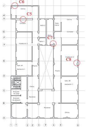
In the case of cove C1, the profile is accompanied by a ladder type reinforcement with 10 mm diameter bars that also presents corrosion. In the fifth level, when executing the coves (Figure 11) it was observed that the reinforcement of the column corresponding to the C6 is an ordinary steel reinforcement that still retains its metallic gray color. In coves C5, C7 and C8, corrosion was observed with loss of section in reinforcements consisting of type I-sections.
On the seventh level the reinforcement of the columns corresponding to the C9 and C10, is an ordinary steel armor that shows good state of preservation. In the case of C9 and C10, they have corrosion with very little section loss. In coves C11 and C12, the reinforcement is constituted by I-sections, with a high level of corrosion with loss of section. Table 6 shows the results obtained from the measured elements:
Table 6 Loss of section of reinforcement measured in columns
| Coves | Axis | Location | Measurement (mm) |
Section
loss (%) |
|---|---|---|---|---|
| C9 | 1´:H | bar diameter | 16,00 | 0,0 |
| C10 | 3:F | bar diameter | 15,37 | 7,7 |
| bar diameter | 9,36 | 12,4 | ||
| C11 | 4:H´ | edge of the flange | 9,99 | Undetermined |
| C12 | 4:C | edge of the flange | 8,57 | Undetermined |
It should be noted that in the case of cove C9, as previously explained, the reinforcing steel has a metallic gray color, however, in the column there is a longitudinal crack that runs along its entire height. This lesion originated as a result of a flexo-compression effort that was not able to support the concrete due to its low mechanical strength and eccentricity of the reinforcement.
On the other hand, in the case of columns with ordinary steel bars, the loss of section was calculated from the nominal diameter of the bars that make up the reinforcement. For columns whose reinforcement is an I-section, it was not possible to calculate the percentage of loss because the nominal measurements are not known.
It is important to note that the concrete that makes up the columns presented very low mechanical resistance, because in the process of executing the coves it did not offer resistance to cutting, crumbling with great ease. To the extent that it descends in the levels, from the seventh to the second, there is evidence of a decrease in resistance, the latter being the most vulnerable to the cut.
3.3 Evaluation of the service life
Figure 12 shows a graphical representation of the service life of a structure proposed by (Castro-Borges and Helene, 2007).
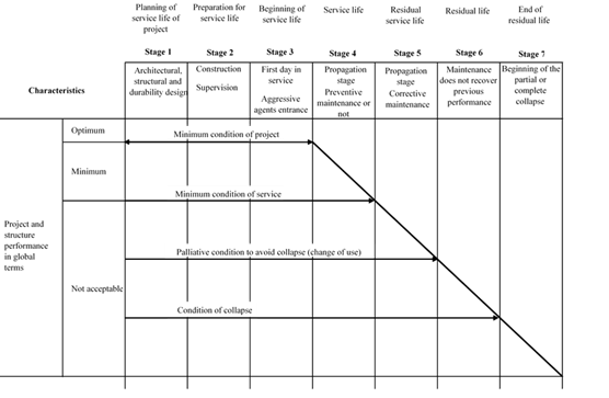
The results of the diagnosis of the slabs and columns show an advanced deterioration that extends to all levels of the building. The extent, magnitude and severity of the lesions show that they have been developing for a prolonged period of time, without the application of adequate maintenance in the time of service, on a scheduled or systematic basis. Based on all the previously presented analysis, it is to be considered in accordance with the proposed service life model, that the building is in the “state 5” in transit to its residual life, where the deteriorations will continue of no corrective measures for repair and maintenance are taken in time.
4. CONCLUSIONS
The damages of a building of the early twentieth century in Havana were diagnosed. In general, damage caused primarily by corrosion of reinforcement steels was recorded throughout the structure. In the case of mid-level and roof slabs, the magnitude of the lesions present in the kitchens and bathrooms areas does not allow their rehabilitation through routine maintenance, because the bars have lost more than 90% of their section.
Considering that the structure is based on a rigidly frame system, these slabs can be demolished and replaced by new systems that lighten the loads of the columns and the structure in general, such as joist and vault, or other techniques. With respect to the columns, many of them are cracked as a result of the corrosion of the bars and I-sections, however the damages are not so significant and can be properly rehabilitated.
The current state of conservation of the property does not present acceptable safety conditions to continue with its exploitation, being necessary to perform various repair actions and the development of a corrective maintenance plan that allows extending the life of the structure.

