


 nueva página del texto (beta)
 Inglés (pdf)
 Artículo en XML
 Referencias del artículo
 Enviar artículo por email
 Citado por SciELO
  Similares en
SciELO
Similares en
SciELO 
 Permalink
1. INTRODUCTION
Nowak and Fischer (2016, p. 297) state that the traffic infrastructure “not just ensures economic performance and efficiency, but also provides mobility and quality of life to the population, hence decisively contributing to the country’s wealth”.
According to Brazilian National Confederation of Transport (CNT, 2018), the road freight transport in Brazil corresponds to 61.1%, and the transport of people corresponds to 82.8% of the total. Bridges and viaducts are directly affected by the predominance of railway mode transport. Beyond being very important in the transport systems, ensuring the proper functioning and safety of these structures has an impact on the socioeconomic developments of surrounding cities and even of a country (Zhou; Chen, 2018; Bastidas-Arteaga, 2018).
Permanent loads, such as self-weigh, and the moving loads, which are represented by the vehicles that commute on those structures, are some of the actions acting on bridges and viaducts. (Schneider; Marx, 2018). The annual number and weigh of the road freight vehicles in Brazilian and worldwide highways have been increasing (Pircher et al., 2011; Han et al., 2015; Deng et al., 2016; Han et al., 2017).
This growth has generated several problems in the constituent elements of bridges and viaducts. Among the structural problems that bridges and viaducts are susceptible, the fatigue needs to be highlighted (Pimentel et al., 2008; Baroni et al., 2009) because the variability and the regime of moving loads make these structures more likely to suffer from this phenomenon.
Liu and Zhou (2018) confirm what has been presented above, and they advocate that “the research on the fatigue problem of reinforced concrete beams is of great significance to the design, maintenance and reinforcement of bridges” (Liu; Zhou, 2018, p. 3512).
Based on this, using the real and actual traffic data from a highway, the fatigue service life of the longitudinal reinforcement bars of beams of three theoretical reinforced concrete bridges with different span sizes will be estimated. Those bridges will be designed according to the Brazilian Code NBR 7188 using the Brazilian Load Model TB 450, which represents a vehicle with 450 kN of total loading (Brazilian National Standards Organization, ABNT, 2013).
1.1 Methodology
As theoretical reference will be used digital scientific articles from journals and congresses in both Portuguese and English languages. Moreover, books, which are references in the area of study, will be used; national and international relevant Codes, such as ABNT NBR 7188:2013, the current Brazilian Code of “Road and pedestrian live loads on bridges, viaducts, footbridges and other structures”, and the Brazilian Code ABNT NBR 6118:2014 - Design of concrete structures - Procedure. The numerical evaluations performed in this research will be made through Analytical Methods using the mathematical equations described in item 2 of this paper. Fatigue life will be determined using the Fatigue Damage Accumulation methodology (Miner's rule), and the bending moments will be determined in the middle span of the reinforced concrete beams using the structural analysis finite element software Ftool (FTOOL, 2008). The choice to use Ftool is because it is a free tool and is widely used in technical and academic projects, either as a pedagogical tool or in the scientific environment.
2. FATIGUE
According to NBR 6118, “fatigue is a phenomenon associated with repeated dynamic actions, which can be understood as a process of progressive and permanent modifications of the internal structure of a material subjected to oscillation of stresses resulting from these actions” (ABNT, 2014, p. 193). Habeeba et al. (2015, p. 2561) explain that the “fatigue is a progressive deterioration of a structure by crack growth, due to a series of stress variations (cycles) resulting from the application of repeated loads, such as induced in bridge components under traffic loads and heavy vehicle crossings”, and those cycles can be low or high (Habeeba et al., 2015, p. 2561).
The stress range is given by the difference of the maximum and minimum stresses, and it is expressed by the following equation (1):
Where: Δσ is the stress range; σmax is the maximum stress and σmin is the minimum stress.
The stress ratio R between the stresses is given by:
Among the different methodologies adopted in the fatigue analysis, the principle of linear damage accumulation according to Miner's rule will be used. This methodology will be adopted due to the fact that in the fatigue of bridges occur random (non-uniform) stress cycles (Santos, Pfeil, 2014). Pimentel et al. (2008) and Wang et al. (2013) state that the cumulative damage in fatigue D linearly relates the number of cycles experienced n to the number of cycles required to cause the structural failure N:
Where: D is the cumulative damage; n i is the number of experienced cycles; N i is the number N of necessary cycles required to cause the structural failure due to fatigue. Wang et al. (2013, p. 3) explains that D is “linearly proportional to n i to each stress range Δσ i ”
Freitas (2014, p. 24-24) comments that “the use of Fatigue Damage Accumulation Methodology has as main advantage its rigor, due to the absence of conversion and simplification equations”. The author also points out that “when the study focusses on a reduced number of elements, the use of this method can be viable”, as it is the case of this research that analyzes reinforced concrete beams (Freitas, 2014, p. 24-25).
Branco et al. (1999) remark the following conclusions about the results that can be obtained to the cumulative damage D:
D>1 - The fatigue life of the analyzed structural element is less than the designed one, so, the structural failure due to fatigue will occur during the stipulated (designed) service life, which requires that measures are taken to delay and or control such a process;
D=1 - The fatigue life due to fatigue of the analyzed structural element is the designed one;
D<1 - The fatigue life due to fatigue is higher than the designed one, so the structural member has a fatigue life, or a residual life (RL).
Based on the determination of the cumulative damage, it is possible to determine the fatigue service life (VU):
In this context, it is relevant to clarify the concepts of Functional Life and Design Service Life. Branco and Paulo (2012, p. 2) advocate that “the characterization of the life of a bridge must begin by defining its functional life, in other words, the characterization of the intended maximum traffic capacity” during the service life of bridges and viaducts.
The authors also explain that the “service life is frequently less than the structural life of the bridge” and, once the problems start to happen, these structures must undergo a rehabilitation process, “for example, increasing their width or building a new bridge near” that bridge with certain issues, “ensuring the maintenance of the functional quality of the crossing” (Branco, Paulo, 2012, p. 2).
It has been claimed by Branco et al. (2013, p. 5) that the Design Service Life “is associated with the safety conditions and use of the structure, namely ensuring that no collapse, excessive deformation, etc. occur”. Branco and Paulo (2012) indicate that bridges and viaducts used to be designed to have a service life of 50 years, however, nowadays, this lifespan went to 75 years, and in some countries and depending on the significance of the work, from 100 to 120 years. Therefore, the fatigue service life is related to the structural life of the bridge under the fatigue aspect.
The called S-N Curves or Wöhler Curves, which are also used in the fatigue life assessment, are graphical representations that relate the modulus of stress (S) to the number of cycles (N) required to cause the failure of the material and are plotted from experimental data (Pereira, 2006; Baroni, 2010).
2.1 Fatigue of concrete
The Brazilian Code NBR 6118 (ABNT, 2014, p. 192) advocates that the fatigue life assessment of bridges needs to be done using the frequent combination of actions, even though the fatigue phenomenon “is controlled by the accumulation of the deleterious effect of repeated loads”, in other words, by the cumulative damage method. Hence, the frequent combination of actions is given by equation 5:
Where: F d,ser is the design value of the actions to the Service Limit State (SLS); F gik are the permanent loads; F q1k is the mains living load; F qjk are the secondary living loads; ψ1 is the reduction factor of frequent combination; ψ 2j is the reduction factor to the transient combination; moreover, ψ1 is equal to 0,5 to beams.
Fatigue loads of high intensity, which can cause damage under 20,000 cycles, are not studied by NBR 6118 (ABNT, 2014), and only the actions of medium and low intensity and the number of receptions up to 2,000,000 cycles are addressed by the Brazilian Code. According to the NBR 6118 (ABNT, 2014, p. 193), “for the consideration of the spectrum of actions, it is accepted that those of vehicles with full load up to 30 kN may be excluded in the case of road bridges”.
Schlafli and Bruhwiler (1998), Ray and Kishen (2014) and Ruiz et al. (2015) hold the position that the mechanic behavior of reinforced concrete elements is closely connected to the reinforcement behavior. Then, the failure of the structure is associated to the failure of the reinforcement that, most of the time, happens under bending moments (Schlafli; Bruhwiler, 1998, Ray; Kishen; 2014, Ruiz et al., 2015).
Maggi (2004, p. 8) shows that the fatigue of concrete “starts in a microscopic scale, and it is associated to the increase of cracks opening and the stiffness reduction”. Among the factors that influence the fatigue strength of concrete include: “stress range, loads history, material properties, loads frequency, stress gradient and backlash periods” (Maggi, 2004, p. 8).
Zanuy et al. (2011) point out that, in a big picture, the repeated cycles acting on a structural member cause stiffness reduction due to excessive cracking and deformation. This loss of stiffness is due to the degradation of concrete in its compressed region and the reduction of the called “tension stiffening”. Junges (2017, p. 91) states that “the term tension stiffening refers to the ability of concrete to carry tensile stresses between cracks due to the transfer of forces from the reinforcement bars to the concrete through adhesion”.
The figure 1 presents the reduction of the tension stiffening as the number of cycles increases, based on tests made by Zanuy et al. (2011). Analyzing this figure, it is possible to highlight two important aspects: as the number of cycles increases, it gets closer to the pure State II; and the gradual reduction of the tension stiffening is due to the loss of adhesion between steel bars and concrete.

2.1 Fatigue in the reinforcement bar
Schlafli and Bruhwiler (1998) establish that the fatigue propagation can be divided in two stages. At the first stage the cracks propagation is stable; at second stage it is seen a brittle fracture in the remaining section (Schlafli; Bruhwiler, 1998). The American Code ACI 215R-74 affirms that the fatigue in the reinforcement is the one that generate major concerns to engineers (ACI, 1997).
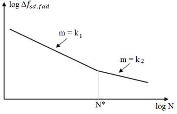
Baroni (2010, p. 42) indicates that “the factors that influence the supporting capacity of steel bars to fatigue are: minimum stress”, diameter, curvature and seam of the bars and the type of beam. Therefore, fatigue sevice life in the steel bars reinforcement can be estimated by the equation (Santos, Pfeil, 2014, p. 41):
Nfad is equal to 106; Δσ fad is equal to Δσ fsd,fad ; m is the path slope, according to figure 2 (Junges, 2017), given by NBR 6118:2014. The values of Δσf sd,fad are given by Table 23.2 from NBR 6118:2014. The maximum and minimum stresses in the reinforcement steel bars can be determined using the following equations:
Where: σ s,max is the maximum compression stress in the bar; σ s,min is the minimum compression stress in the bar; x i is the distance of neutral axis to the bottom of the beam; αE is the ratio between the modulus of elasticity of steel reinforcement bars and concrete.
In this research it will be used passive reinforcement bars, the S-N curves can present two values, k1 = 9 e k2 = 5. From this, the constants Const1 and Const2 can be determined for both curves through the following equations
For different values of Δf sd,fad , to 106 cycles, the constants are given according to table 1.
Table 1 Values de Δf sd,fad
| Δf sd,fad,min (MPa) | Const 1 | Const 2 | Δf sd,fad (MPa) |
| 190 | 3.64E+17 | 6.45E+26 | 205.21 |
| 185 | 3.18E+17 | 5.08E+26 | 199.81 |
| 180 | 2.78E+17 | 3.97E+26 | 194.41 |
| 175 | 2.41E+17 | 3.08E+26 | 189.01 |
| 165 | 1.80E+17 | 1.81E+26 | 178.21 |
| 150 | 1.12E+17 | 7.69E+25 | 162.01 |
Source: Own Author (2019).
Hence, every time that Δσ s is huger than Δf sd,fad , the steel reinforcement areas must be multiplied by the fatigue coefficient k.
2.3 Fatigue in reinforced concrete bridges
Zhang et al. (2012) state that the economic growth that China has passed in the last years has contributed directly to the significant increase in heavy vehicles traffic on the country's highways. This fact implies in the fatigue resistance of highway bridges and viaducts. Through the conducted studies, the authors obtained some conclusions. First, they claim that the Miner`s rule is adequate and a “is a reasonable and practical method for determining the fatigue damage coefficient” of simply supported beams (Zhang et al., 2012, p. 793).
The authors also concluded that “it is recommended that the fatigue damage coefficient be updated to the new” Chinese road bridge moving load code for bridges with spans less than 20 m (Zhang et al., 2012, p. 793).
Rossigali et al. (2015, p. 124) claim that there is a growing concern and search for load models more compatible with reality “for highway bridge design in Brazil”, and those models “are under development by assembling real traffic database, traffic simulations, analytical-numerical modeling of the dynamic interaction between vehicle and structure and statistical extrapolations”. Considering this statement, the authors analyzed small span reinforced concrete bridges with two lanes single carriageway under different traffic scenarios.
The authors used structural reliability techniques and probability distributions to analyze the real flow of vehicles. At the end, they had concluded that the current live load model given in the current Brazilian code NBR 7188:2013 “is not appropriate to represent the actual traffic effects and may be, in some cases, non-conservative” (Rossigali et al., 2015, p. 124).
Alencar et al. (2016, p. 2) hold the position that “the imposition on the structure of new traffic conditions associated with material fatigue behavior can lead to structural damage with different levels of severity, and as the magnitude of the loads carried increases, the problem becomes even more relevant”.
Wan et al. (2015) and Xin et al. (2017) also present arguments to emphasize that stating that the authorities and structural engineers have been paying more attention to the process of fatigue arising from the increase of heavy vehicles on the highways and their speed.
Almeida and Fortes (2016), Mota et al. (2018) and Camargo et al. (2018) demonstrate that the loads from the most recent actual vehicles commuting on Brazilian highways may be higher than those calculated by TB 450.
More recent researches such as that developed by Deng and Yang (2018) have dealt with the formulation of methods for determining the permission and legal weight limits for heavy vehicles considering the accumulated fatigue damage on bridges. The authors obtained results related to fatigue damage for different stress variations in their studies, and they indicate that those results “can be used to determine the weight limit for both new and existing bridges” (Deng; Yang, 2018, p. 7).
Braz et al. (2018, p. 1) analyzed “four models reinforced concrete bridge build with two beams based on the Brazilian and European codes”, and the four bridges are “hyperstatic, with fck of 50 MPa, CA-50 steel and main spans of 20 m”. Analyzing and comparing the results, the authors concluded that:
The European normative treatment proved to be more conservative than the Brazilian one regarding reinforcement fatigue and design. This behavior is a reflection of the European regulatory rigor that adopts design vehicles and load coefficients specific to the fatigue, as well, only one fatigue strength value for different reinforcement diameters (Braz et al., 2018, p. 10).
3. HEAVY VEHICLES DATABASE
In order to carry out the relevant assessments and calculations related to the fatigue process, the actual annual traffic volumes information between the years of 2009 to 2017 are used, and they were provided by CCR RodoAnel, which manages 29.30 kilometers of the western stretch of the highway Mario Covas, which integrates the Raposo Tavares, Castello Branco, Anhanguera, Bandeirantes and Régis Bittencourt highways” (CCR RODOANEL, 2018). The data collected refers to the annual number of road freight vehicles with 2 to 6 axes, according to the table 2.
Table 2 Annual Commercial Vehicle Traffic
| Year | Vehicle of
2 exes |
Vehicle of
3 exes |
Vehicle of
4 exes |
Vehicle of
5 exes |
Vehicle of
6 exes |
|---|---|---|---|---|---|
| 2009 | 5,531,774 | 3,306,437 | 1,180,226 | 663,505 | 889,091 |
| 2010 | 6,476,748 | 4,213,663 | 1,874,607 | 1,995,312 | 1,773,380 |
| 2011 | 3,820,060 | 4,652,486 | 2,169,154 | 2,170,282 | 2,109,843 |
| 2012 | 7,097,189 | 4,775,874 | 1,344,816 | 2,082,505 | 2,289,120 |
| 2013 | 6,208,545 | 5,072,068 | 1,792,046 | 2,492,961 | 3,194,281 |
| 2014 | 5,309,203 | 5,258,467 | 883,935 | 2,796,359 | 4,004,225 |
| 2015 | 5,008,912 | 2,540,180 | 856,232 | 2,487,752 | 4,076,946 |
| 2016 | 4,714,630 | 4,142,964 | 816,219 | 2,226,043 | 3,817,949 |
| 2017 | 4,718,774 | 3,941,475 | 988,906 | 2,205,195 | 3,898,191 |
Source: CCR RODOANEL (2018).
4. RESEARCH METHOD
For the calculations and verification due to fatigue, it is used a theoretical model with a structural system with a bridge with two simply supported beams with spans L by 10 m, 15 m and 20 m, respectively named V10, V15, V20. The choice for bridges made only with 2 beams is because Brazil still has a great number of old bridges and viaducts built with 2 beams. According to data from National Department of Transport Infrastructure (DNIT, 2017), 12.95% of the bridges and viaducts have spans up to 10 m and 16.40% from 10.01 to 20 m. Furthermore, 86.28% of the Brazilian bridges and viaducts have width up to 13 m (DNIT, 2017). The “Manual de Inspeção de Pontes Rodoviárias” (DNIT, 2004) states that bridges and viaducts build in Brazil after 1985 must have transverse section with total width of 12.80 m and lane width of 12.00 m. Based on this, the cross section of 12.80 m will be adopted for the three spans analyzed in this paper.
Two single carriageways are assumed for all analyzed bridges. Moreover, following the guidelines from “Manual de Projeto de Obras-de-Arte Especiais” (DNER, 1996), each carriageway will have adopted dimension of 3.60 m, totalizing 7.20 m of width, and 2.40 m to each shoulder. The figure 3 demonstrates the transverse cross section of the three bridges.
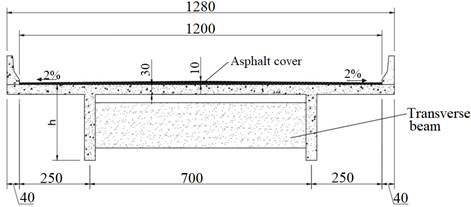
There are intermediate transverse beams placed in each 5 m with constant width of 0.30 m and high of 0.80 m. The transverse beams are not connected to the slabs, so they have the locking function only. Due to the simplification of the calculations, the following hypotheses are adopted: the bridge slab is not usually of constant thickness, but in this research the slab thickness is adopted as constant; constant thickness is adopted for the 10 cm asphalt cover. The “T” section of the beams used is shown in figure 4.
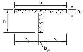
The table 3 presents the adopted values to the transverse cross sections of the three studied bridges, and table 4 demonstrates the properties of the materials used.
Table 3 Bridge beam cross-sectional dimension values
| Bridge | b1 (cm) | b3 (cm) | bw (cm) | bf (cm) | hf (cm) | h (cm) |
|---|---|---|---|---|---|---|
| V10 | 100 | 100 | 35 | 235 | 30 | 100 |
| V20 | 200 | 200 | 35 | 435 | 30 | 200 |
| V30 | 300 | 300 | 35 | 635 | 30 | 300 |
Table 4 Properties of the materials
| Concrete | Steel | ||
|---|---|---|---|
| fck (MPa) | fyk (MPa) | fyk (MPa) | Es (MPa) |
| 35,0 | 500,0 | 500,0 | 210.000 |
4.1 Brazilian load train
Regarding the positioning of the Brazilian load train, TB 450, the Brazilian Code NBR 7188:2013 clarifies that the it can assume any position along the entire cross section of the bridge where there is a road lane, provided the wheels are in the most unfavorable position, “including shoulder and safety bands”. The distributed load must also be applied in the most unfavorable position, “regardless of the road lanes” (ABNT, 2013, p. 4). Figure 5 shows the TB 450 vehicle positioned in the most unfavorable section of the bridge cross section.The same position is assumed for the three bridges studied in the paper.
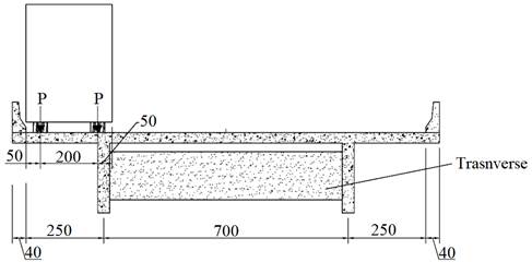
Figure 5 Load train vehicle TB 450 in cross-sectional for maximum stress on the left beam of the figure (dimensions in centimeters) (Own Author, 2019).
This critical position is determined using the technique of influence lines, and a simplified model already established that can be seen in numerous publications such as Carvalho (2017). In this case, the support reaction line of influence is used, thus, considering the load train (TB 450) in the position that leads to the greatest reaction of the studied beam, it is possible to determine the set of loads named longitudinal load train (“trem tipo longitudinal”, the original name is Brazilian Portuguese, TTL), which the bending moment forces of the beams will be determined with.
Regarding the determination of the moments, in this case the bending one, using the TB 450, the following considerations are made:
a). Following the guidelines of NBR 6118 2014, item 23.5.3, the combination of actions to be considered will be frequent. Therefore, the maximum and minimum moments arising from the combinations of permanent and living loads in the middle of the beam span will be given by the frequent combination of actions;
b). It is considered the diameter of the 25 mm of the steel reinforcement bar.
4.2 Actual traffic
The vehicles that commute, over the bridge's lifetime, can assume various positions in its cross-section, which ultimately generate different internal stretches in the beams according to the position in which the moving loads are.
Toledo (2011) evaluated the positioning of real vehicles on highways in relation to traffic lanes. The author concluded that “the analysis with the vehicle on the centered lane is a good approximation for the calculation of the fatigue life of the structure, since the results obtained for this case were more unfavorable than for the vehicle in a eccentric position” (Toledo, p. 63, 2011).
Eurocode 1: Actions on structures - Part 2: Taffic loads on bridges (2002) states that for the cross-sectional assessment of the vertical loads of real vehicles traveling on the highways, half of them travel centered on the traffic lane and the others are distributed symmetrically along the lane, as shown by the frequency distribution of vehicle transverse positioning in a bridge shown in figure 6 (EUROCODE 1, 2002).

This research adopts the following considerations in the living load model of real vehicles:
a). The procedure for determining the maximum TTL is the same as for the TB 450 vehicle; however, the actual freight vehicles are positioned as shown in figure 7;
b). Crosswise the vehicles shall have the same dimensions as shown in Figure 7;
c). 100% of the vehicles are positioned in the center of the traffic lane;
d). It is considered to be only a freight vehicle traveling on the bridge;
e). The bending moment and other calculations consider the loads due to the actual freight vehicles and the distributed loads according to NBR 7188 (ABNT, 2013), representing the small vehicles that can follow the passage of the freight vehicles;
f). Moments arising from actual freight vehicles are not weighted by the Frequent Combination Reduction Factor for Service Limit State (ELS) ψ1 because NBR 6118 (ABNT, 2014) does not provide for such a procedure for actual loads.
g). Each vehicle generates a stress cycle, which is used to determine the fatigue life by the Cumulative Damage Method.

5. ANALYSIS OF RESULTS
Using the normative load train TB 450 and vehicles from 2 to 6 axes, the maximum bending moments in the middle of the beam span for the three types of bridges is calculated. It is important to mention that the values calculated for moving (living) loads are multiplied by the impact coefficient (CI), according to the Brazilian code, that varies according to the size of the span. Table 5 presents the bending moments calculated due to bridges own weight and the moving loads for the simply supported structures.
Table 5 Calculated bending moments for the simply supported beams
| Bending moments in the middle of the span (kN.m) | ||||||||
|---|---|---|---|---|---|---|---|---|
| Beam | CI | Permanent
load |
TB
450 |
Vehicle
of 2 exes |
Vehicle
of 3 exes |
Vehicle
of 4 exes |
Vehicle
of 5 exes |
Vehicle
of 6 exes |
| V10 | 1.35 | 1162.1 | 1251.3 | 443.1 | 541 | 563.9 | 632.1 | 585.9 |
| V15 | 1.33 | 2725.5 | 2269 | 881.6 | 1051.2 | 1143 | 1261.1 | 1192.3 |
| V20 | 1.27 | 5096 | 3130.1 | 1447.5 | 1688.8 | 1849.6 | 2037.9 | 2002.8 |
In determining the number of cycles N to fatigue in steel, it is necessary to determine the value of “m” of the S-N curve. As the calculated stress range in steel is less than the limit stress variation for the diameter of 25 mm, which is 17.5 kN/cm2, m is equal to 9.
The figure 8 presents the consumed life of each respective year analyzed for each bridge. In addition, in table 6 are presented the estimated fatigue service life of the longitudinal reinforcement steel bars, showing the consumption of fatigue resistance over the nine years considered, and the time required to reach 100% of consumption.
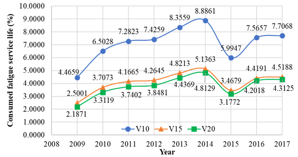
Table 6 Fatigue service life of the steel reinforcement
| Bridge | Consume in 9 years (%) | 100% of consume (years) |
|---|---|---|
| V10 | 64.19 | 14.02 |
| V15 | 37.00 | 24.32 |
| V20 | 34.03 | 26.45 |
It is important to mention that the results presented do not consider the previous fatigue damage or any other previous damage, only during the 9 years of data considered; hence, the bridges are considered as new ones.
Because it is a high vehicle flow per year, with an average annual traffic of 16,200,000, the three analyzed bridges presented fatigue service life of less than 30 years, to the longitudinal reinforcement. Moreover, it is verified that the consumption of 100% of the fatigue strength in the longitudinal reinforcement varies according to the span, and the smaller the span, shorter fatigue service life.
To increase the fatigue life of the steel reinforcement bars, one or some of the following possibilities are suggested: 1) Increase the number of beams; 2) Change the cross section of the analyzed bridges; 3) Modify the dimensions of the transverse profile of the beams; 4) Increase the compressive strength characteristic of concrete; 5) Review the procedures for verification and/or fatigue design of railway bridge beams present in Brazilian codes.
6. CONCLUSIONS
Based on the analyzes performed in this article, it is possible to conclude that although the normative vehicle TB 450 presents bending moments in the middle of the span greater than those presented for those actual vehicles considered here, in the bridges analyzed in this paper, the high number of vehicles in the analyzed section requires attention to the fast consumption of fatigue resistance.
The required times to achieve 100% of fatigue service life consumption in the longitudinal reinforcement bars on the three analyzed bridges have different values, but all would have fatigue life less than 30 years. This result is critical and worrisome, especially if it is considered a design service life from 50 to 80 years.
Therefore, it is necessary to adopt certain measures to increase the fatigue life of these reinforced concrete bridges simply supported, such as using a larger number of beams per deck of bridge and/or modifying the beam cross section.
Furthermore, the high age of Brazilian bridges and viaducts must be considered because the analyzes and calculations performed here consider that the bridges are new, whose damages are only those presented over the nine years analyzed. Hence, special attention should be given to these aged structures.

