


 nueva página del texto (beta)
 Inglés (pdf)
 Artículo en XML
 Referencias del artículo
 Enviar artículo por email
 Citado por SciELO
  Similares en
SciELO
Similares en
SciELO 
 Permalink
Nomenclature
| a - shear span bf - width of the layer of CFRP bw- width of the beam bp - width of bonded CFRP plate bc - width of concrete in pull-out experiment Lb - Length of bonded CFRP Le - Effective length of CFRP Tp . thickness of bonded CFRP plate c - height of the block of rectangular compression equivalent of the concrete c1 - factor obtained by calibration of results (equal to 0.64 for CFRP) d - effective beam height d’- centroid position of the compressed reinforcement fc - concrete compression strength fctm - average tensile strength of concrete ffe - effective strength of the CFRP fs - strength of steel Af - area of reinforcement applied to the beam As - steel area of the tensile reinforcement As’ - steel area of compressed reinforcement Ef - modulus of elasticity of the CFRP Es - modulus of elasticity of steel Fcc - compression resulting L - total beam length P - applied load in the experimental test Ts - tensile component due to the tensile reinforcement α - reduction coefficient due to the propagation of inclined cracks |
β1 - coefficient that determines the approximation
of the resultant compression curve of the concrete to a rectangle
according to the recommendations of ACI 440-2R (2008) εbi - strain found in the covering of the tensile reinforcement in the beam before the strengthen εc - concrete strain εcu - concrete ultimate strain εf - carbon fiber strain εfd - limit value of fiber strain to be adopted in the sizing and verification of reinforcement εfe - effective strain in the FRP εfu - ultimate strain observed in the polymer at the moment of failure εs- strain in the tensile reinforcement εs’ - strain in the compressed reinforcement εys - yield strain of the flexural reinforcement Gf - Interfacial fracture energy s - local slip; se - elastic component of local slip; sf - local slip when bond stress τ reduces to zero; s0 - local slip at τmax; Bl - bond length factor; Bw - width ratio factor; τ - local bond stress; τmax - maximal local bond stress; τu - average bond stress. |
1. Introduction
During the last four decades, the development of materials from the theoretical and technological points of view of advanced composite materials have resulted in an expanded use. Their outstanding engineering properties such as high specific strength and stiffness, lower density, high fatigue endurance, high damping and low thermal coefficient (in fiber direction), etc., have resulted in a constant use in the aerospace, marine and automobile industries.
Reinforced concrete structures may be damaged after a few years in service or exposure to aggressive environments, such as marine and/or industrial environments, and are therefore in need of repair. Then, to allow for a load carrying capacity higher than the original design value, the structural members need to be retrofitted. Corrosion is a major cause of deterioration in civil infrastructure, especially steel bridges, with consequences ranging from the progressive weakening of the structural elements due to cracking and loss of cross-section, to sudden collapse. The high strength-to-weight and stiffness-to-weight ratios of composites make them attractive for use in infrastructure rehabilitation. A common repair/retrofitting technique for concrete beams, is to bond a plate to the soffit of the beam. Initially, steel plates were employed and more recently, attention has been directed towards the use of carbon fiber reinforced plastic composites (CFRP) plates, which offer higher strength/weight, and several attractive attributes mentioned before and an improved durability over their steel counterparts. Furthermore, these advanced composites are being considered as a replacement to the conventional steel in reinforced concrete structures due to a continuing decrease of the cost of CFRP materials and the development of synthetic adhesives based on epoxy resins, (C.K.Y. Leung, (2001), Swamy R.N. et al, (1987), Hamoush S.A. (1990), Norris, (1997), Karbhari, et al, (1995), Saadatmanesh, (1995)).
The performance of the CFRP as a reinforcement agent for concrete elements has been studied, from the structural, material, and application method. The flexural strengthening of RC beams using composites can be provided by epoxy bonding of CFRP plate to the portion of the elements subjected to tensile stresses, with fibers parallel to the principal stress direction. If the composite material fibers are placed perpendicular to the cracks, a large increase in strength and stiffness is achieved as compared to situation where fibers are placed oblique to the cracks. Also, strength enhancement for RC beams of approximately 200% is achieved with carbon fiber reinforced polymer composites (CFRP). The flexural performance of strengthened RC beams is affected by several factors such as modulus of elasticity of CFRP and its center of gravity location relative to the neutral axis, width of laminate, length of laminate, amount of main and shear reinforcement, number of CFRP plies, level of loading, lamination configuration, concrete strength and cover, damage and loading condition, etc. (Sandeep S.et al, 2008).
Adhesion of the external CFRP to the concrete substrate is of critical importance for the effectiveness of the reinforcing mechanism, because it means the transfer of stresses between concrete and the FRPC in order to develop a composite action. Several reports can be found in the technical literature studying different aspects that affect the efficiency of the reinforcing of CFRP.
The main objective of this paper is to review the literature (analytical/experimental) of the different parameters that affect the load-transfer mechanisms from the RC element to the CFRP and to discuss the effects of various parameters that affect the durability, especially, parameters related to the adhesive-concrete interface as well as the composite material laminate performance when exposed to hygro-thermal environments. The discussion is kept on a descriptive level and the reader is advised to refer to the cited references for details of parameters and mathematical models.
Parameters such as strength on the average bond strength and the force transfer from the composite plates to the concrete were studied by Chajes, M.J. et al, (1996). They observed two failure mechanisms direct concrete shearing beneath the concrete surface and cohesive-type failure, depending on the type of adhesive and concrete. They also showed that the surface preparation of the concrete can influence the bond strength. Similar studies were conducted by Yoshizawa et al, (1996) who reported that the roughness of the concrete face had an effect on the load bearing capacity of the specimen. Also, when the failure mode of the joint was governed by shearing of the concrete, the ultimate bond strength was proportional to the square root of the concrete strength f'c. They also found that there is an effective bond length for a joint beyond which no further increase in failure load can be achieved.
2. The mechanics of concrete-cfrp adhesion
2.1 Linear analysis of the bonded Concrete-CFRP joint
Debonding between concrete and the externally bonded CFRP sheets/strips externally in flexural and shear strengthening cases decreases the strength efficiency of the CFRP materials or causes a deficiency in member ductility (Dai, et al, 2005). The interface bond strength or local stress-slip property has been shown to influence the peak flexural or shear strength of RC members retrofitted using CFRP by means of analytical models (Buyukozturk and Hearing 1998, fib 2001) giving birth to various bond strength, anchorage length and local bond stress-slip models (Chen and Teng 2001). As stated by Lu, et al (2005), an accurate bond-slip model is of fundamental importance in the modeling of FRP-strengthened RC structure. A sound understanding of the behavior of the interface between the CFRP and concrete is the key factor controlling debonding failures in CFRP-strengthened RC structures. Therefore, for the safe and economic design of externally bonded CFRP systems, in this paper we make reference to the analysis presented by De Lorenzis, L. 2001, and mention other models available in technical literature (see Figure 1), (Taljsten B. 1997, Bizindavyi L. 1999, Mander J. B. 1998, Jeffries, J. M. 2001).
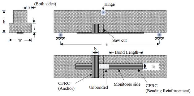
Figure 1 Test specimen showing dimensions of the concrete beam and the position and dimensions of the CFRC bending reinforcing as well as the CFRP anchor. (After De Lorenzis, L. 2001)
Considering static equilibrium and compatibility relations of a differential element of sheet of length dx, and assuming a linear elastic behavior of the CFRP sheet and that the stiffness of the concrete is much higher than the stiffness of the composite, that is, negligible strain in the concrete and that the adhesive is subjected to shear forces only, the following differential Equation results. At moderate load levels, a linear bond stress-slip behavior can be adopted:
Where s is the slip, ( is the bond stress, x the coordinate along the bonded length of the laminate, t the thickness and E the elastic modulus of the CFRP. At moderate load levels, a linear bond stress-slip behavior can be adopted. A solution of the Equation 1 is
Where:
The constants C 1 and C 2 can be determined from the boundary conditions. If the origin of the coordinate x corresponds to the free end of the sheet (x = 0), where no strain exists, and x = l (being l the bonded length) corresponds to the end of the CFRP sheet where the external load is directly applied, the boundary conditions are:
And equations 2a-c become
The slip modulus K can be estimated using a simple shear model
as the ratio of the shear modulus of the adhesive and the thickness of the
adhesive layer. Also, when CFRP based on sheets instead of plates are used, the
slip modulus
Where:
Equation 7 can also be used to estimate the shear modulus of the primer. The local (-slip curves can be obtained from experimental data as follows. The bond stress, (, can be found by equilibrium of forces, considering also the linear elasticity of the FRPC.
Where (r is the CFRP strain to failure, therefore, the ((x) diagram can be obtained from the first derivative of the strain vs location diagram multiplied by the elastic modulus E and the thickness.
Figure 2 illustrates some bond stress ( - slip curves obtained from tested specimens at a load level corresponding to imminent peeling. This was identified as the load level at which the strain distribution becomes linear. Typical bond (-slip curves should consist of an ascending branch with continuous stiffness degradation to the maximum bond stress and a curved descending branch reaching a zero-bond stress at a finite value of slip. While a precise bond-slip model should consist of a curved ascending branch and a curved descending branch, other shapes such as a bilinear model can be used as a good approximation. An accurate bond-slip model should provide close predictions of both the shape and fracture energy (area under the bond-slip curve) of the bond-slip curve. None of the existing bond-slip models provides accurate predictions of both the shape and the interfacial fracture energy as found from tests. The area underneath the ( - slip curve, indicated as Gf, is the fracture energy per unit area of the bonded joint (Lu X.Z. 2005).
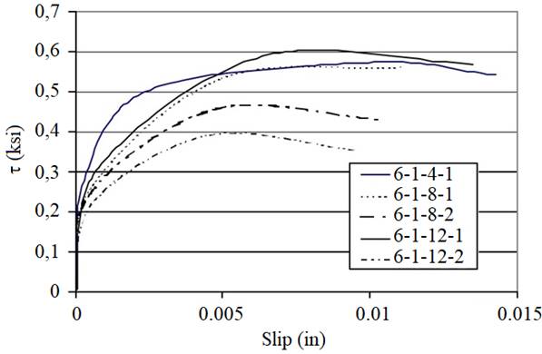
Figure 2 Local (-slip relationships for specimens with different CFRP bond lengths (4, 8 and 12 in) bonded on the tension side of a concrete beam. Note: 1 in= 25.4 mm; 1 psi= 7.03 kPa (De Lorenzis et al (2001)).
In a recent paper, Hamze-Ziabari and Yasalovi, (2017), made a summary of existing equations for the prediction of load transfer between concrete and the effective load transfer length of the CFRP. These equations were derived from either fracture mechanics theoretical considerations or from empirical equations calibrated with experimental datasets or combinations of the two. However, the accuracy of these models seemed to be limited. For the sake of completeness, some of these equations are also reproduced in this review (see Table 1):
Table 1 Equations to estimate the maximum transferable load Pmax as well as the effective length of the FRPC.
| Reference | Equation maximum transferable load Pmax | Effective length and considerations |
|---|---|---|
| Chen, F.J., Teng, G.J. (2001) |
|
|
| De Lorenzis et al(2001) |
|
Gf is the fracture energy per unit area of the joint, assumed to be equal to 1.06 N-mm/mm2 |
| Teck-Yong el al(1987) |
|
|
| Van Gemert(1980) |
|
|
| Tanaka (1996) |
|
|
| Maeda et al (1997) |
|
|
| Yuan, Wu and Yoshizawa, (2001) |
|
|
| Neubauer and Rostasy (1997) |
|
|
| Khalifa et al (1998) |
|
|
| Adhikary and Mutsuyoshi (2001) |
|
|
| Dai et al (2006) |
|
|
| Lu et al 2005 |
|
|
| Camli and Binici (2007) |
|
|
| FIB model (2001) |
|
|
| CNR-DT200/2004 2004 |
|
|
2.2 CFRP strengthening of beams
The observed failure modes of concrete beams reinforced with CFRP sheets have been reported by Teng et al (2003) and further analyzed by Ferreira et al (2018). They reported three typical failure modes: (1) tensile failure of the CFRP when its tensile strength is lower than the applied load; (2) debonding of the reinforcement at the laminate-concrete interphase; and (3) a cohesive failure of the concrete and there is separation of the reinforcement together with a layer of concrete.
The first failure mode is attributed to a brittle mode of failure, but it is evident that the CFRP-concrete bond strength is higher. The second mode of failure is attributed to a lack of anchorage of reinforcement, excessive cracking of the beam or faults in the bonding. Again here, failure of the adhesive bond strength may be cause by normal stresses at the end of the CFRP strip, where a stress singularity is known to exist [Leung, 2001, A.R. Khan et al 2014 and R.A. Hawileh et al 2015].
The analysis of the strengthening of a concrete beam with a CFRP layer loaded in bending presented by Ferreira et al (2018) considered that the ratio of the reinforced beam framework is equivalent to the addition on the initial reinforcement ratio with the contribution from the reinforcement (see Figure 3).
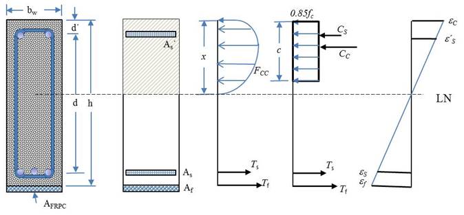
Figure 3 Stress-strain diagram of a steel-reinforced concrete beam strengthened with CFRP (After Ferreira et al 2018)
Where ρ is the ratio of the reinforcement of the beam before strengthening, A f is the area of reinforcement applied to the beam, E f is the modulus of elasticity of the CFRP, E s is the modulus of elasticity of steel, b w and h are the width and height of the beam respectively. The recommendations for the sizing of the CFRP reinforcement according to the American code ACI 440-2R are as follows: The limit value of the fiber strain to be adopted in the sizing and verification of the reinforcement is expressed in terms of the modulus of elasticity of the CFRP, and ε fu, the ultimate strain observed in the polymer at the moment of failure and n, the number of layers of CFRP.
The effective strain in the CFRP composite ε fe is expressed as a function of the concrete ultimate strain ε cu and the strain in the covering of the tensile reinforcement in the beam before the strengthening, ε bi and x, the position of the neutral axis.
f fe is the effective strength of the CFRP;
ε s ' is the strain in the compressed reinforcement and, d’ is the centroid position of the compressed reinforcement.
The strain in the tensile reinforcement, ε s , is expressed by:
f s ', the strength in the steel of the compressed reinforcement is given as a function of the strain in the compressed reinforcement ε s ´ and the elastic modulus in the steel;
The strength in the steel of the tensile reinforcement f s is given by
The position of the neutral axis is calculated as follows:
A s is the steel area of the tensile reinforcement; A s ' is the steel area of the compressed reinforcement; β 1 is a coefficient that determines the approximation of the resultant compression curve of the concrete to a rectangle, being 0.85 for concrete with f c values lower than 28 MPa, which decreases linearly by 0.05 for each 7 MPa above that limit of tensile strength. The minimum value for such a coefficient, according to ACI 318 (2014), is 0.65.
The conditions at the interface between the composite and concrete require a full understanding from the mechanics point of view. Different epoxy resin formulations or any other adhesive used will result in completely different behavior of the concrete-composite joint. In addition, the geometrical design of the laminate and anchors will also influence the mechanical behavior and consequently, the effectiveness of the reinforcement. Then, as a first step, whenever possible, and depending on the availability of testing equipment, preliminary studies of the adhesion parameters between the composite and concrete are required to determine the lengths of the joints for effective stress transfer needed to achieve the composite's strength capacity.
3. Environmental effects on the CFRP-concrete interface bond strength
The interface at the concrete- CFRP has been recognized as the region where the efficiency of the load transfer from the structural element to the CFRP laminate takes place. As stated by Swamy RN et al (1987), the properties of the epoxy adhesive is of paramount importance as they varied considerably with the thickness of the test specimen and the rate of loading. Similarly, the fiber-matrix interphase is regarded as an important region of the composite laminate performance.
This matrix behavior at the concrete-CFRP is of particular interest in advanced composite materials, since its use in structural applications with exposure to the environment, requires that the material meets very strict performance, durability and safety standards. Moisture transport in polymeric systems is related to the availability of "free space" or "free volume" of molecular size in the structure of the polymer, as well as its affinity to water. [M. R. Vanlandingham, et al (1999) ]. Such availability of "free spaces" depends on the microstructure, morphology and density of crosslinking, which are functions of the degree of curing, stoichiometry, stiffness of the molecular chains and the cohesive energy density of the polymer. The polymer-water affinity is related to the presence of hydrogen bond sites along the polymer chains that create sites of attractive forces between the water molecules and those of the polymer. Water molecules that are free to move through holes or free volume are known as adsorbed molecules. In the case of the epoxies it is also known that they have a significant free volume, particularly at temperatures 50-150 ° C below the Tg. The epoxy-water affinity is relatively strong because polar hydroxy groups (-OH) are created by the opening of the epoxy group by reaction with primary and secondary amines. [M. J. Adamson, 1736]. Then, in the case of these composites based on carbon fibers and epoxy matrix, those properties that are dominated by the matrix or fiber-matrix interface are degraded by the absorption of moisture while those dominated by fibers are not essentially affected. In particular, the interfacial shear strength, the interlaminar shear strength, and depending on the carbon fiber-epoxy resin laminae stacking sequence in the laminate, the edge effects also become points of possible failure initiation as well as the mode II fracture toughness and the interlaminar toughness. This degradation is attributed to the weakening of the fiber-matrix interphase and to swelling of the matrix and plasticization of the matrix [J. I. Cauich-Cupul, et al (2011) , E. Pérez-Pacheco, et al (2011), S. Wang et al, (2002), L.E. Asp, (1998), M. Todo, et al, (2000), R. Selzer et al, (1995), M. J. Adamson, (1980), D. A. Bond, (2005), M. R. Vanlandingham, et al (1999)]. Moisture absorption can also cause a decrease of the residual stresses produced from the curing thermal gradients and thus, resulting in a decrease of fracture properties. The effects of humidity are considerably aggravated by the temperature and further complicated by the action of mechanical stresses imposed on the material. [J. B. Aguiar, et al (2008) ].
Furthermore, these composite materials are exposed to different environmental conditions during their useful life, such as moisture, temperature and ultraviolet radiation and therefore to the possibility of synergistic effects on degradation mechanisms. Hence, there is always a concern for the long-term durability of these materials to be exposed to combined environmental conditions of humidity, temperature and ultraviolet radiation. [Springer, G.S. (ed.) (1984), Ranby, B.and Rabek J. F., (1975)]. Both, ultraviolet radiation and humidity have negative effects mainly on the mechanical properties of the epoxy resin and the fiber-matrix interface and thus affect the integrity of the composite [W. B. Liau, et al, 1998].
The subject of durability of the FRPC strengthening systems, as a whole, has been a major concern in structural rehabilitation applications. Behavior of FRPC strengthened beams subjected to freeze-thaw, wet-dry and temperature cycles or various aqueous solutions prior to loading have been studied by a limited number of researchers (Bank, et al, 1995, Gheorghiu C. et al, 2004, Grace N. F. et al 2005, Wang C. Y , et al, 2004, Xie M., 1995, Katz A., 1999). There has been a fundamental change in the approach to the subject. As opposed to subjecting a specific composite material to an environmental exposure for a specified time period and then performing mechanical tests to obtain “data” for design use, the more recent approach has been to try to develop an integrated chemical and mechanical set of tests that provide an understanding of the mechanisms of degradation within the composite material. These papers combine macromechanical test methods with investigations of changes in material composition together with a scanning electron microscopy to develop models that attempt to explain the change of mechanical properties in terms of the quantitative changes in the chemical nature of the materials and qualitative observation of the degradation phenomenon (Bank and Gentry, 1995).
Buyukozturk O, 1998 and Grace and Singh, 2005, and concluded that the long-term exposure to humidity is the most detrimental factor to the bond strength between CFRP plates and fabrics and RC beams. Beams strengthened with CFRP plates and exposed to 10,000 hours of 100% humidity (at 38 ± 2 °C) experienced an average of 33% reduction in their strength. The onset of delamination was the primary mode of failure for all of the test beams.
The durability of carbon fiber reinforced polymer (CFRP) pretensioned piles driven in tidal waters and an experimental study to assess the likely effect of diurnal/seasonal temperature change on twelve precracked CFRP pretensioned beams designed to fail by rupture of the prestressing rods were kept outdoors in two salt water tanks and simultaneously subjected to wet/dry cycles (simulating tides) and hot/cold cycles (simulating temperature variation), (Aiello, et al, 2001). Durability was assessed from flexure tests conducted periodically over the nearly 3-year exposure period. The results of the tests indicated that durability was largely unaffected, although both bond degradation and reductions in ultimate capacity were observed in some of the exposed specimens. Degradation appeared to be linked to the extent of precracking damage sustained prior to exposure. This suggests that when CFRP pretensioned piles are used, driving stresses should be carefully monitored to minimize damage.
Because of the change in behavior under varying environmental conditions, it can be said that a complete understanding of the effects these materials have on the performance of retrofit systems has not been achieved. In particular, various failure mechanisms that the retrofitted concrete beam can manifest, including the debonding and delamination mechanisms of FRP from the concrete beam, are not well known. More studies are needed to develop a better understanding of the shear capacity of retrofit sections, the effects in the anchorage regions of the FRP laminate, and failure mechanisms of debonding and delamination. Topics of future study should also include effects of material compatibilities and their resistances to degradation through both environmental and load cycles, and the assessment of retrofitted system integrity through the use of nondestructive evaluation [Nakaba 2001].
Strictly speaking, the application of a fiber-reinforced composite laminate layer on the tensile side of the beam, either by bonding a laminate or by forming a composite material in situ, using the epoxy resin and fibers unidirectionally oriented in a textile, a manual lay-up procedure, will result in two interphase, the concrete-resin interphase and the fiber-matrix interphase, as shown in Figure 4. Both interphases are susceptible to be affected by exposure to the environment. However, in the technical literature on the subject of RFPC beam retrofitting, there is only reference to the concrete-laminate interphase.
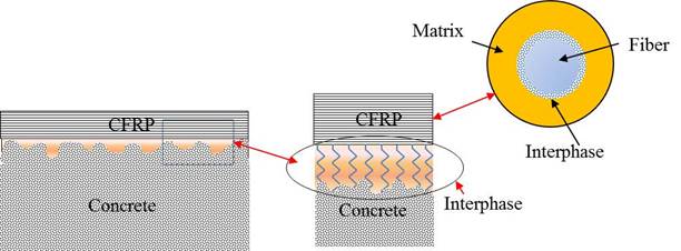
Figure 4 Schematic representation of the formation of dual interphases formed by the use of laminates or fabrics to retrofit steel reinforced concrete beams. One concrete-resin interphase and one fiber-matrix interphase.
Karbhari and Engineer, 1996, investigated the degradation of the composite-concrete interface after exposure to environmental conditions that include moisture, sea water, freezing and freeze-thaw. In this investigation, the performance of plated beams was considered from aspects related to materials and durability. The effect of five different environmental conditions was studied and they showed that the selection of the appropriate resin system is critical to success and pointed out the dangers of selecting systems with low glass transition temperatures and drastic drops in instantaneous modulus as a function of temperature. Results indicated that degradation occurs primarily at the level of the resin in contact with the concrete, and that due care should be taken of changes in composite stiffness due to moisture exposure and the consequent resin plasticization, as well as due to stiffness increases under cold conditions (Aiello, et al, 2001, Plevris N, 1999, Soudki KA 2000, Wang CY 2004).
J. I. Cauich-Cupul et al, (2011) studied the effect of moisture uptake in the interphase in epoxy-single IM7-carbon fiber composites and showed a detrimental effect on the mechanical properties of the matrix, and this deterioration was attributed to a decrease of its glass transition temperature. Three levels of the IM7 carbon fiber-epoxy interface were studied. The first was the IM7 carbon fiber with the sizing removed, then, the fiber-matrix adhesion level was increased using a silane coupling agent to treat the IM7 fiber surface and third, the IM7 fibers were treated with nitric acid to produce more chemical reaction sites with the silane coupling agent.
The quality of the fiber-matrix interface was assessed using the single fiber fragmentation test and the fiber-fragment length, considered as an indicator of interfacial quality which indicated a continuous deteriorating effect of moisture uptake. That is, a short fiber-fragment length indicated a strong fiber-matrix interphase and a weak (or deteriorated) fiber-matrix interphase was indicated by a long fiber-fragment length (see Figure 5). Furthermore, the role of swelling of the matrix because of moisture uptake on the residual stresses is considered to be important when considering the deterioration of interfacial shear properties. The contribution of the radial stresses was seen to decrease rapidly and the mechanical component of the fiber-matrix adhesion also decreased rapidly for higher moisture contents in the matrix and/or interface.
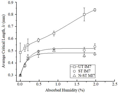
Figure 5 Fiber fragment length a function of matrix-interphase absorbed humidity in the composite, for untreated surface carbon fibers (UT IM7); silane coupling agent treated surface IM7 carbon fibers (ST IM7) and, nitric acid and silane coupling agent treated surface IM7 carbon fibers (N-ST IM7), (J. I. Cauich-Cupul et al, (2011))
Perez-Pacheco, et al (2013) concluded that the microstructure of the interphase played a significant role in the moisture diffusion process in a carbon fiber-epoxy laminate. Figure 6 shows the moisture absorption isotherms for a composite laminate subjected to several relative humidity environments. They also concluded that the effects of absorbed moisture on the interfacial region was detrimental to the interfacial strength between the fiber and the epoxy matrix and thus, to the performance of the composite. The use of 3-glycidoxypropyltrimethoxysilane as a fiber-matrix coupling agent enhanced the fiber-matrix adhesion. The plasticization, swelling stresses and any epoxy degradation because of hydrolysis may have contributed to the matrix failure mechanisms. Plasticization of the epoxy matrix by moisture lead to the change in its glass-transition temperature (Tg) thus affecting the mechanical response of the composite. It was observed that the tensile strength of laminates made with the silane coupling agent showed a decrease but after a moisture uptake of approximately 0.45 %, the tensile strength remained constant. Then, the use of a proper silane coupling agent to enhance adhesion resulted in improved mechanical properties and reduced the dependence of the properties on humidity under tensile loading (see Figures 7 and 8).
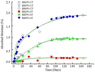
Figure 6 Absorption of moisture in the composite material laminate for different relative humidity environments. Without treatment: (UT) silane surface treatment (ST). RH25% UT, RH55% UT, and RH95% UT, and with silane surface treated fibers RH25% ST, RH55% ST and RH95% ST. (Perez-Pacheco, et al (2013))
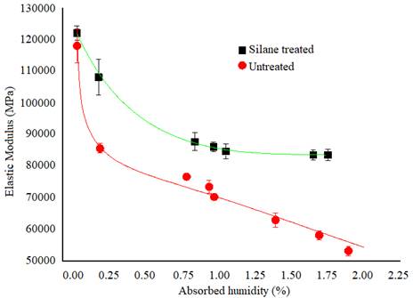
Figure 7 Behavior of the elastic modulus with respect to the moisture absorbed for the composite material with the treated and untreated fiber, respectively. (Perez-Pacheco, et al (2013))
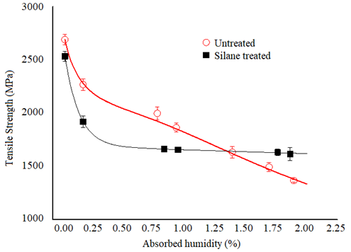
Figure 8 Tensile strength of a CFRP material made on the composite material after suffering hygroscopic degradation, for two different fiber-matrix interface conditions, that is, for treated and untreated fibers, respectively (Perez-Pacheco, et al (2013))
The behavior and potential of combining corrosion protection and FRP patching repair techniques to retrofit corrosion damaged RC beams has been demonstrated by Swamy RN et al, 1999 and Sebastian WM, 2001. They found that this type of arrangement can improve the load carrying capacity of cracked and corroded RC beams and provides the space for coating the corrosion protection materials. They also proposed that the equally spaced U-anchorage strips together with the longitudinal strips form an external reinforcing system for the corroded RC beam constrains the extension of the fiber in the longitudinal direction in the intersection area. Since the strain value is higher at this site, it enables the full usage of the fibrous composite material’s strength. Hence any design that can reduce the stress concentration effect at the intersection area of the longitudinal and U-shaped anchorage strips may help the beam to escape from the premature failure mode of fiber breakage and reach its designed load carrying capacity.
As it can be seen, environmental issues are extremely important when designing a concrete-composite laminate joint for beams retrofitting. All the models described in numeral 2.1 of this paper consider the mechanical properties of the composite laminate, which as seen in Figures 7 and 8, decrease as a function of absorbed humidity. Therefore, the composite laminate should be designed with dimensions such as thickness and width, appropriate to the stiffness and strength values, either those properties estimated after being degraded by the absorption of humidity or by including an appropriate safety factor to the composite mechanical properties before exposure to the environment. Another approach would be to provide a protective coating to prevent moisture absorption, especially at the laminate edges.
4. Conclusion
An effective method for strengthening existing concrete beams in bending consists on bonding fiber-reinforced composite laminates on the tension faces of the beams. However, it is often difficult to develop the full composite strength capacity because of premature failure due to delamination and peeling-off of the laminate. Conditions at the interface between the composite and concrete require a full understanding, and preliminary studies of the adhesion parameters between the composite and concrete are required to determine the effective stress transfer lengths needed to achieve the composite's strength capacity. A theoretical analysis for the behavior of such composite-to-concrete bonded joints has also been included in this review. The durability of the composite material-concrete interphase is also very important, especially when the structure is exposed to both thermal and moisture together. In the technical literature, no reference is made to the two interfacial issues, that is, the concrete-polymeric resin interphase and the fiber-matrix interphase in the composite itself. The durability of the composite laminate is shown to be affected by moisture absorption thus resulting in a reduction of both strength and stiffness higher than 30%.

