


 nueva página del texto (beta)
 Inglés (pdf)
 Artículo en XML
 Referencias del artículo
 Enviar artículo por email
 Citado por SciELO
  Similares en
SciELO
Similares en
SciELO 
 Permalink
1. Introduction
The need to rehabilitate reinforced concrete structures by strengthening may arise because of the lack of maintenance during their lifespan and their adaptation to new uses when the option of demolishing and rebuilding them is not viable. In this case, some studies were conducted regarding the strengthening of reinforced concrete structures. However, because of the ongoing development in this topic of structural engineering, there is still no specific methodology for analyzing the structural behavior of the rehabilitated beams.
According to Reis (Reis, 1998), intense studying in scientific research on the strengthening and rehabilitation of reinforced concrete structures is very important. This is mainly to define the designing rules better, understand the behavior of the strengthening of structures over time, and identifying approaches for analyzing the adhesion between the materials as well as their properties. These studies would enable determining which materials, techniques, procedures, and rules are more suitable to be used during the realization of structural rehabilitation. Therefore, the literature on the strengthening of reinforced concrete beams such as the papers by Helene (Helene, 2000), Cheong and MacAlevey (Cheong and MacAlevey, 2000), Reis (Reis, 2003), Alfaiate and Costa (Alfaiate and Costa, 2004), Altun (Altun, 2004), Santos (Santos, 2006), Lima (Lima, 2015), and Deghenhard et al. (Deghenhard et al., 2016) have been extremely important for the advancement of research in this area.
Although there are various strengthening techniques, this work will focus on the method of rehabilitation of reinforced concrete beams via the introduction of steel bars and epoxy structural adhesive (jacketing). The study of this technique, despite being antiquated, is still very important because of two simple reasons. First, it continues to be a widely used strengthening technique for small and medium works in Brazil. Second, in this research, serious problems were identified with this type of strengthening, which need further discussion.
The main objective of this work was to study the rehabilitation of reinforced concrete beams by the addition of steel bars and epoxy structural adhesive.
2. Experimental program
2.1 Characteristics of the beams
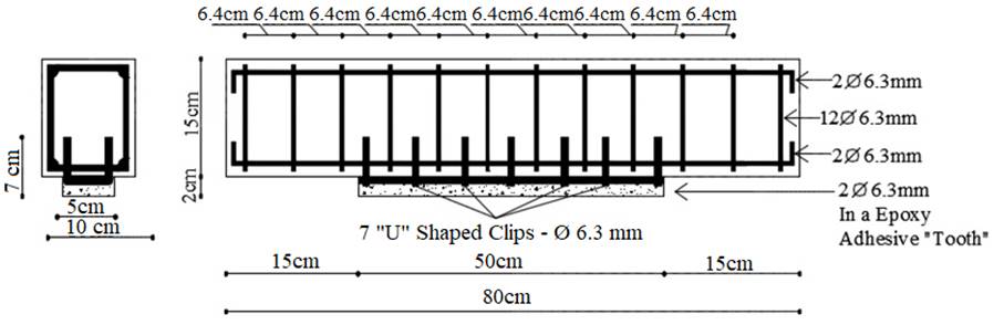
For this study, the Structure and Material Research Group (GEM) of Vale do Acaraú State University (UVA) produced five reinforced concrete beams, of which four were strengthened and one beam was used as a reference (not strengthened). All the beams were produced with the same dimensions: 80 cm length (with a span of 60 cm), 15 cm height, and 10 cm width, as shown in Figure 1.

The reference beam was not strengthened and is denoted as Beam E1. The other beams (E2, E3, E4, and E5) were strengthened by different approaches. All the beams had two longitudinal reinforcement bars with a diameter of 6.3 mm, and twelve transversal reinforcements (stirrups) with a diameter of 6.3 mm and 6.4 cm spacing. This arrangement of reinforcement bars was chosen so that the failure of the beams could be due to flexure. Figure 2 displays the details of the reinforcement of the five beams.

Beam E2 was strengthened to flexure with the insertion of two bars of ( 6.3 mm and 50 cm length in a “tooth” formed with epoxy adhesive (Figure 3).

Beam E3 was also strengthened to flexure with the insertion of two bars of ( 6.3 mm and 50 cm θlength in a “tooth” formed with epoxy adhesive. To improve the anchorage of the strengthening bars to the substrate of the beam, seven “U” shaped clips of 7 cm height and 4.5 cm width were inserted (see later in Figure 7), which penetrated 5.5 cm into the beam (Figure 4).
Beam E4 was strengthened to flexure with the insertion of two bars of ( 6.3 mm and 30 cm length in a “tooth” made with epoxy adhesive. The sizes of these bars were reduced to remain almost completely inside the pure flexure region (Figure 5).

Beam E5 was also strengthened to flexure with the insertion of two bars of ( 6.3 mm and 30 cm length in a “tooth” formed with epoxy adhesive. As in Beam E4, the sizes of these bars were reduced for them to remain practically completely inside the pure bending region (Figure 6). In Beam E5, to improve the anchorage of the strengthening bars to the substrate, four “U” shaped clips with 7 cm height and 4.5 cm width were inserted (according to Figure 7), which penetrated 5.5 cm into the beam (Figure 6).

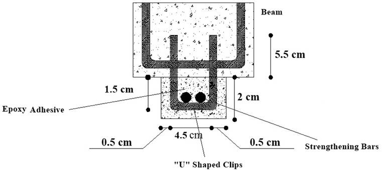
Figure 7 Details of the clip inserted in Beams E3 and E5 to assist in the anchorage between the strengthening and beam.
The compressive ultimate strength of concrete (fc) was obtained by an axial compression test of the cylindrical specimens on the same day of the tests of the beams, and it achieved an average resistance of 34.91 MPa. The tensile ultimate strength of concrete (ft) was obtained by the indirect tensile test of cylindrical specimens (Brazilian test), on the same day of the tests of the beams, and it achieved an average resistance of 3.13 MPa. The tests for obtaining the compressive and tensile strengths of concrete were performed according to NBR 5739 (ABNT-NBR5739, 2007) and NBR 7222 (ABNT-NBR7222, 2011). Table 1 lists the characteristics of the tested beams.
Table 1 Characteristics of the tested beams.
| Beams | Strengthening | Bottom reinforcement | Stirrups | fy (MPa) | Es (GPa) | fc (MPa) | ft (MPa) | Ecs (MPa) |
|---|---|---|---|---|---|---|---|---|
| E1 | Without Strengthening | 2 ( 6.3 mm | 12 ( 6.3 mm | 500 | 210 | 34.91 | 3.20 | 29357.64 |
| E2 | 2(6.3 mm Length = 50 cm | |||||||
| E3 | 2(6.3 mm + 7U Length = 50 cm | |||||||
| E4 | 2(6.3 mm Length = 30 cm | |||||||
| E5 | 2(6.3 mm + 3U Length = 30 cm | |||||||
| fy = Yield limit of the
steel according to the manufacturer; Es = Modulus of elasticity of the steel according to the manufacturer; fc = Average resistance to compression of concrete on the date of the test; ft = Average resistance to tensile of concrete on the date of the test; Ecs = Secant modulus of elasticity of concrete calculated by NBR6118 (ABNT - NBR6118, 2014). | ||||||||
Although the analyzed beams had reduced dimensions compared to real beams, it is necessary to emphasize that the aim of this work was not to determine any correlation between the reduced model and a prototype, through a dimensional analysis and laws of similarity, in a quantitative analysis. The aim was to only compare the structural behavior of the strengthened beams (E2, E3, E4, and E5) and reference beam (E1) in a qualitative analysis.
2.2 Test system
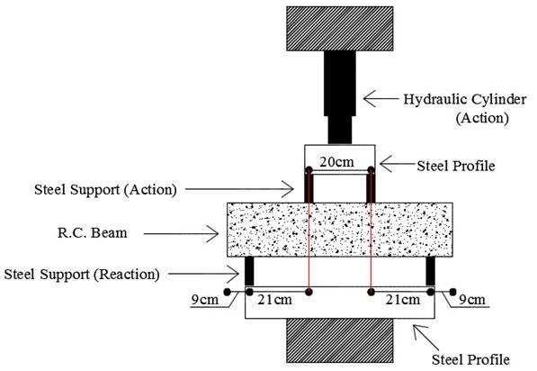
The beams built in this research underwent experimental tests performed at the Laboratory of Materials of Vale do Acaraú State University. They were submitted to the Stuttgart test, in which two concentrated forces equidistant from the supports were applied. This allowed studying the strengthening in the regions submitted to pure flexure and where shear effects (simple flexure) were also observed. Figure 8 illustrates a hydraulic press used for the tests.
The experimental tests are divided into two stages. In the first stage, beams E2, E3, E4, and E5 are subjected to a cracking load of 50 kN, which is equivalent to 60% to 80% of the failure load. The aim of this first stage was to crack the beams to simulate the need of strengthening. After removal of the 50 kN load, the beams were rehabilitated with steel bars and epoxy adhesive. The epoxy adhesive used to assist the anchor strengthening the bars to the substrate of the beam was Sikadur 31, which was not mixed with sand. The resistance to compression of Sikadur 31 at three days of age was 60 MPa, and the rehabilitation followed the manufacturer recommendations (Sika, 2015).
One week after the rehabilitation, the second stage of the experimental tests began, which consisted of loading the beams through the Stuttgart test. The process was conducted with load steps of 10 kN until the beam exhibited failure. In each interval of the load applied to the beam, crack formation was examined and marked with a whiteboard marker to assist in the identification of the failure modes.
2.3 Computational model
The beams made for the experimental tests were also simulated in ANSYS software, which uses the finite element method for the discretization of structures. The computational modeling with the software was performed to replicate the conditions of the Stuttgart test performed in laboratory. Therefore, the same characteristics of the used materials were considered to obtain consistent results, which could then be correlated to the results of the experimental analysis. Figure 9 illustrates the modeling of the stirrups of Beam E1 and one of the other four beams, because of their identical rebars and spacing.

The supports and points of application of the loads were modeled with a 20 mm width, instead of 10 mm as in the tests, so that there were no stress concentrations in these regions, which could make the numerical convergence complex and cause an early failure.
To validate the results provided by the ANSYS software with the literature and study the effect of discretization on the precision of the results, the beams were modeled considering the individual properties of the steel and concrete materials: the modulus of elasticity, Poisson coefficient, and interactions between both the materials, as listed in Table 2.
Table 2 Properties of the Materials
| Characteristics | Concrete | Steel Bars (CA-50) | Epoxy Adhesive (Sikadur 31) |
|---|---|---|---|
| Elasticity Modulus | 26838 MPa (1) | 210 GPa (2) | 4.3 GPa (3) |
| Poisson coefficient | 0.2 (4) | 0.3 (5) | 0.2 (5) |
|
(1) Secant modulus of
elasticity of concrete calculated by NBR6118 (ABNT -
NBR6118, 2014); (2) Modulus of elasticity of the steel according to the manufacturer; (3) Modulus of elasticity of the epoxy adhesive according to the manufacturer; (4) Poisson coefficient adopted; (5) Poisson coefficient according to the manufacturer. | |||
Three-dimensional eight-node element Solid65 was used to model the concrete. This solid has three degrees of freedom in each node, and it is capable of cracking and crushing under tension and compression, respectively. This element considers the Willam-Warnke failure criterion for compression, and the tensioned region of the concrete is considered as an isotropic material with softening. The element is illustrated in Figure 10.

Three-dimensional element Link180 was used for modeling the reinforcements. This element has two nodes with three degrees of freedom in each node, and it is widely used to represent bars, trusses, and cables in a simplified way. This element only resists axial forces and assumes that the material exhibits the same behavior under compression and tension. An elastoplastic model is defined with a bilinear tension-strain graph as the failure criterion.
Shell element Shell181 was used to model the strengthening bars and epoxy adhesive. This type of element is mainly used for modeling jacketing with carbon fibers, but it can also be used for modeling external strengthening with steel bars. This element has four nodes with six degrees of freedom in each node and the capacity of plasticity, and its depth is considered in the analysis.
The size of the mesh was 10 mm. According to Muliterno and Pravia (Muliterno and Pravia, 2016), in nonlinear analysis, the load is divided into a series of substeps so that in each substep the stiffness matrix is updated to consider the nonlinear alterations in the structural stiffness before going to the next substep. This analysis used 500 substeps, and in each load step, the load was applied from bottom to top and a force-based convergence criterion was used. The load was applied until a magnitude error occurred, which was considered as the moment of failure. The supports were inserted into the two superior faces of the elements of reaction and defined as zero displacements in the X, Y, and Z axes. The CEINTF command was executed to combine the nodes of the beam and reinforcement, considering that there was a perfect adherence between both the materials.
3. Results and discussions
3.1 Loads and Failure Modes
After a visual verification of the conditions of the beams after the failure, each tested beam was correlated to the computational model and compared to the reference beam.
After all the beams achieved their ultimate load, a comparison was made between the rehabilitated and reference beams, analyzing the ultimate loads and failure modes. The most efficient strengthening method among the strengthened beams was also identified. Table 3 lists the details of the strengthening methods, ultimate load, and failure mode of each beam.
Table 3 Description of the strengthening methods, loads, and failure modes of the beams.
| Beam | Strengthening | VANSYS (kN) | VExper (kN) | VExper / VAnsys | Failure Mode |
|---|---|---|---|---|---|
| E1 | Without Strengthening | 85.00 | 80.00 | 0.94 | Flexure |
| E2 | 2 ( 6.3 mm (length = 50 cm) in “tooth” with epoxy adhesive | 89.75 | 108.00 | 1.20 | Flexure |
| E3 | 2 ( 6.3 mm (length = 50 cm) in “tooth” with epoxy adhesive and 7 “U” shaped clips | 87.75 | 96.00 | 1.09 | Shear (Compression Strut) |
| E4 | 2 ( 6.3 mm (length = 30 cm) in “tooth” with epoxy adhesive | 90.00 | 116.00 | 1.29 | Flexure |
| E5 | 2 ( 6.3 mm (length = 30 cm) in “tooth” with epoxy adhesive and 4 “U” shaped clips | 80.00 | 74.00 | 0.93 | Flexure |
| VAnsys = Computational
failure load indicated by the Ansys software; VExper = Experimental failure load. | |||||
3.2 Effect of the Solicitation Mode
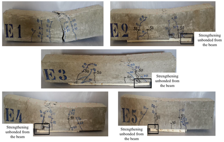
In the experimental tests, when the beams were subjected to the second stage, Beam E2 achieved an ultimate load of 108 kN, and it was verified that it failed after the strengthening unbonded from the beam, causing failure by flexure. Comparison with the reference Beam (E1) verified that its resistance increased by 35%.
The analysis of the results of the test of Beam E3 revealed that it failed after the strengthening unbonded from the substrate of the beam. However, unlike Beam E2, it had a different failure mode due to the compression of the strut. Comparison with the reference beam verified that the mechanical resistance of Beam E3 increased by 20%.
The analysis of the results of Beam E4 verified similar to Beams E2 and E3; it failed by flexure after the strengthening unbonded from the beam. Despite the indications of a compressed strut caused by the clips, the failure mode was flexural failure. It exhibited an increase of 45% in its resistance relative to the reference beam.
Beam E5 had the same failure mode as Beams E2 and E4; it was caused by flexure after the strengthening unbonded from the beam. Compared to the reference beam, its resistance decreased by 7.85%. Figure 11 shows the tested beams after their failure.
The results obtained through the ANSYS software verified that the ultimate loads yielded by the software agreed to the results achieved in the experimental tests. The failure modes of the beams and variation in the results compared to the reference beam were also similar. However, there was a difference in the strengthening: in the experimental test, the strengthening debonded from the beams before they underwent failure, but in the analysis, this did not occur because the friction between the beam and strengthening was not considered. Figure 12 presents the load-displacement plot of the five beams obtained from the computational analysis.

Dahmani, Khennane, and Kaci (Dahmani, Khennane, and Kaci, 2010) emphasized the symbology of ANSYS for the types of failure due to flexure (by flexural crack), shear (by shear crack), and compression (by crushing). These symbologies are presented as the labels in Figure 13. In addition, Dahmani, Khennane, and Kaci (2010) claimed that these symbols could also be combined depending on the type of failure. It is important to emphasize that this type of failure shown by ANSYS is a local failure, for example, the opening of a crack and a localized crushing. It alone does not provide the failure of the entire beam. A combination of these localized failures is what characterize the failure of the beam as a whole.

The aim of the numerical analysis of the strengthened beams was to show the stress distribution in the beams after the insertion of the strengthening, to provide results for comparison with the experimental results.
The analysis of the image, as generated by ANSYS (Figure 13), exhibiting the cracked beam the instant before it underwent failure as well as the location of the clips and strengthening. This verifies that in the region where the beam is strengthened, the appearance of compression stresses is very perceptible, mainly where the first clip is inserted in the beam (from left to right). From the correlation with the experimental test, it can be noted that this is the same region where concrete is crushed (Figure 11), i.e., the region where the beam undergoes failure.
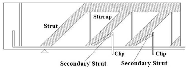
The use of clips in the strengthening of the beams, which was aimed at improving the anchorage, generated concentrations of undesirable stresses in the beams. In the analysis of this problem using the Strut and Tie Model, a secondary strut from the top of the clip to the bottom of the stirrup was observed, which overloaded the existing strut (Figure 14).
4. Conclusions
In this work, the analysis of the results verified that the beams with clips assisted in the anchorage between the beam and strengthening (E3 and E5). More precisely, for Beam E3, the failure mode was a compressed strut, which could be reasoned by the increase in the field of compression of the beam caused by the addition of the clips. For Beam E5, which failed under a lower load than the reference beam (E1), it was verified that after perforating the beam to insert the clips, its stiffness was reduced, thus damaging the strength of the beam.
Beam E4 experienced the highest failure load, and it was only distinguishable from Beam E2, for which the same strengthening technique was used, through its length. It can be concluded that the strengthening of Beam E2 was effective in the region of simple flexure until it unbonded from the beam and underwent failure. The strengthening of Beam E4 was effective in the region of pure flexure, which explained its higher ultimate load in comparison to Beam E2 and all the other tested beams.
The aim of the computational analysis of the strengthened beams was to show the stress distribution in the beams after the insertion of the strengthening to compare them with the real results and validate them. Thus, it can be concluded that in general, the performed analysis satisfactorily simulated the experimental tests, explaining the failure due to the diagonal compression of Beam E3.
Analysis of the strengthened and reference beams revealed that Beams E2 and E4 were under superior ultimate loads compared to the other beams. However, it can be concluded that in this study, the addition of the clips to Beams E3 and E5 damaged their strength. Moreover, the unbonding of the strengthening, which occurred in all the strengthened beams, was because the epoxy resin has an elasticity modulus significantly lower than of the other materials of the system. Therefore, when a strengthened beam was loaded, because of insufficient stiffness, the resin did not transfer all the tension that it received from the lower face of the beam. This resulted in the unbonding of the strengthening, indicating that only steel works. The scenario would be different if the materials had similar elasticity moduli. Thus, despite Beams E2, E3, and E4 having larger ultimate loads than the reference beam, the system does not operate efficiently. Therefore, it is not recommended to use this type of strengthening because it is ineffective and can be dangerous.
It is important to emphasize that the conclusions of this work are limited only to the results of the tests of the five beams presented here. Other future research studies with more tests of beams and with and without strengthening are necessary for a better validation of this research.

