


 nueva página del texto (beta)
 Inglés (pdf)
 Artículo en XML
 Referencias del artículo
 Enviar artículo por email
 Citado por SciELO
  Similares en
SciELO
Similares en
SciELO 
 Permalink
1. Introdution
The design of a structural project is a very complex task since, in addition to the steps of launching, designing and detailing the structural elements, the designers must foresee measures that avoid or hinder the occurrence of pathological manifestations. In general, structures are designed for a 50-year life. For this to be achieved, preventive actions must be taken, which prevent the resistant capacity of the structural elements from being lost in the short term. An example of preventive action corresponds to the waterproofing of the exposed surface of the structural component to the external environment. It acts as a mechanical barrier that prevents the entry of harmful substances or even substances that result in chemical reactions whose products are damaging, inside the structural elements.
In elements of reinforced concrete, a type of very common pathological manifestation that promotes the degradation of the structural element is the spalling. It may occur at room temperature due to corrosion of the submerged framework inside the concrete, for example (Stukovnik et al., 2014). In this context, Wang et al. (2013) define that the deterioration of reinforced concrete structures occurs in two stages. In the first one, there is the degradation of the protective barrier of the reinforcement, allowing the aggressive agents to enter the element. In this process, called depassivation, the structural element does not lose its resilient capacity. Regarding the second step, the deterioration of the structural element itself occurs, in which the process of corrosion of the reinforcement is initiated, followed by the spalling of the concrete surface and, later, the collapse of the structural element.
In addition to the aggressive agents, actions like fire and explosions can also lead to degradation of structures. Currently, due to the increase in the number of cases of residential buildings in a fire situation, many designers have admitted that the design of structures at room temperature, although essential, is not enough to meet the structural safety criteria. Thus, the structural elements must also be designed to meet the required fire resistance time (Kobes et al., 2010).
In everyday life, the risk of fire is imminent. It may be caused by a short circuit of an appliance, improper electrical wiring or gas leakage. In the context of the study of structures submitted to fire, it is essential to know the curve that characterizes the evolution of the temperature of the gases over time, responsible for heating the structural element. It should be noted that no fire is the same as the other, since there are many parameters involved to determine the temperature evolution of the structural element, such as: degree of ventilation of the structure, type and amount of fire load.
In this regard, it becomes difficult to define an average temperature and time that residential buildings commonly reach when they are in a fire situation. Thus, the technical standards allow the adoption of a standard heating curve for the construction of models in experimental analysis. This is the standard fire model; whose standardization allows the treatment of the fire in a simpler and more approximate way.
On reinforced concrete structures, concrete acts as a thermal barrier reducing the flow of heat to steel. This is because concrete presents better thermal properties compared to other materials, such as low thermal conductivity and high specific heat, which decrease heat propagation into the cross section. In any case, because there is a heating, both materials tend to lose rigidity and mechanical resistance. Ingham (2009) explains the mechanisms of microstructural degradation of concrete in a fire situation. When the temperature of the material reaches about 100ºC, the free water present in the aggregates and in the matrix evaporates, increasing the capillary porosity. At this moment, there is a small loss of resistance of the material. When the temperature rises and reaches 300ºC, there is a loss of water bound to the cement matrix. Up to 600ºC, the aggregates undergo thermal expansion and there is an increase of internal tension. Between 600°C and 800°C the carbonate constituents undergo decarbonation and, in the range of 800°C to 1200°C, the components disintegrate, and the concrete is calcined.
Kodur and Agrawal (2016) studied the mechanisms of failure in structural elements under fire. They explain that the deterioration of a structure is due to both the disintegration of parts of the concrete (spalling) and consequent elevation of the temperature in the steel bars, as well as the appearance of permanent deformations induced by the heating of the materials.
According to Deeny et al. (2008), the spalling that occurs in structures exposed to fire can have three origins. The first origin relates to the collapse of the aggregate near the heated surface, the second one to the disintegration of the corners of the concrete and the third to the fragile rupture of the heated surface due to the appearance of internal stresses from the evaporation of the free water. While the first origin is responsible only for surface damage and therefore does not affect the resistant capacity of the material, the second and third ones promote disintegration of concrete parts, leading to loss of mechanical strength (Khoury, 2000; Hertz, 2003).
After the fire it is necessary to evaluate if there was damage in the resistant capacity of the structural elements. If it has occurred, it should be checked the extent of it and thus choose either to destroy the structure or to recover the structural elements. The latter alternative can be achieved using structural reinforcement techniques, in order to restore the bearing capacity of the degraded structure (Reis, 1998). Among the current reinforcement techniques and those of particular interest for this work are the bonding of steel sheets and that of carbon fiber reinforced polymers on the concrete surface. Both were chosen because they present little increase of the useful section of the structural element and do not require, in the constructive process, concreting (Obaidat, 2011). Despite the research done so far, with authors such as Lin and Zhang (2013), Firmo et al. (2015) and Jiangtao et al. (2017), who investigated the behavior of several types of reinforcement when exposed to high temperatures, none of them present reinforcement design for fire-retarded reinforced concrete structures. In addition to the behavior of the structural elements under high temperatures, it is important that the designer knows how to dimension the structural reinforcement for the situation described. Thus, this work proposes a comparative study between the two types of reinforcement previously mentioned, to be used in reinforced concrete beams degraded by the action of the fire and designed subject to flexure. Therefore, the thermal gradient was defined inside the beam, from a numerical modeling and the necessary reinforcement was calculated so that the structure returned to the resistant capacity for which it was dimensioned.
2. Structural reinforcement
2.1. Reinforcement with carbon fibers
According to Fard (2014), the use of carbon fibers as structural reinforcement is more advantageous than the adoption of bonded-in steel sheets. This is due to the high rigidity and mechanical strength of the carbon fibers, which, together with their low specific mass, promotes an increase in the bearing capacity of the structure without adding its final weight. Moreover, corrosion resistance also represents an advantage of carbon fibers over bonded-in steel sheets. Among the disadvantages of using carbon fibers are the high cost and low performance of the fibers when subjected to fire.
In general, the carbon fiber reinforcement system is composed of two main elements: the carbon fiber, which is the element responsible for the mechanical resistance of the system, and the epoxy matrix (Figure 1), formed by epoxy resin resulting from the combination of epichlorohydrin and biphenol. The epoxy matrix is responsible for the transfer of the tensile stresses in the structure to the carbon fibers, being made by both friction and adhesion (Machado, 2007). The matrix involves all the carbon fibers present in the reinforcement, providing both mechanical strength and resistance to the aggressive agents that can deteriorate the fibers. Fard (2014) points out that the surface must be clean, free of powdery materials and the finish should be planned in order to prevent loss of adhesion between the resin and the concrete surface.

Regarding the executive process, the carbon fiber application system consists of five stages. Initially, the concrete surface is prepared by inserting a primer layer, whose function is to form a stable base free of dust and contaminants. Afterwards, the surface is regularized leaving it free of protrusions for later application of the carbon fiber. Then, the epoxy resin is applied followed by the carbon fiber blanket and the resin again. Finally, in order to protect the parts exposed to the sun against UV radiation, a finishing layer is made with acrylic paint.
Regarding the arrangement of the described system, the fibers should be oriented in the direction of the tension lines that they fight. Machado (2002) describes that fibers besides having a high tensile strength, have good shear strength, albeit to a lesser extent than the previous one. For the latter situation, the reinforcement is positioned in the regions of the supports in order to counter the shear stress.
According to Chowdhury et al. (2008) and Raoof and Bournas (2017), one of the main concerns in the use of carbon fiber reinforcement in structural elements is related to their combustibility. At high temperatures, the resin responsible for attaching the carbon fiber blanket to the concrete tends to degrade, generating toxic smoke and increasing the size of the flames. Wang et al. (2003), Forter and Bisby (2005) and Chowdhury et al. (2008) point out that when the temperature in the reinforcement reaches that corresponding to the glass transition of the resin, around 93ºC, the degradation of its mechanical properties begins. In addition to the mechanical resistance, the authors verified that, for temperatures higher than the glass transition of the resin, there was a reduction of the adhesion between the reinforcement and the concrete.
There is no definition in the literature about the temperature at which the total degradation of the mechanical properties of the reinforcement occurs, commonly called critical temperature. Chowdhury et al. (2008) points out that it occurs between 300ºC and 400ºC, which corresponds to the combustion temperature of the resin. On the other hand, for Kumahara et al. (1993) and Wang et al. (2003) this critical temperature is around 250°C. Despite these heterogeneous values, Tanano et al. (1997) found that the critical temperature depends on the resin composition used in the reinforcement. These authors identified in their tests two critical temperatures depending on the type of resin used, 250ºC and 860ºC.
Another advantage of carbon fiber reinforcement is its residual strength after exposure to high temperatures. Forter and Bisby (2005) found that when the reinforcement is exposed to a temperature of up to 300°C and then cooled to room temperature, it recovers its mechanical strength and stiffness.
2.2. Reinforcement by the addition of bonded-in steel sheets
The other object of study of this work corresponds to the technique of reinforcement by bonding thin steel sheets to the concrete surface. Its principle consists basically in the creation of a structural system composed of concrete-glue-steel, in which thin steel sheets are bonded, by means of epoxy resin and/or screws, to the surface of the concrete, significantly increasing the resistance of the element stresses, bending moment and shear stress.
Souza (2008) and Adorno et al. (2000) state that the bonding of the sheets to the structure can be done by means of epoxy resin applied in the area of contact between the element and the sheet (Figure 2a), or by metal screws with epoxy resin injection in the holes (Figure 2b), where the former is the most widely adopted solution in the market. This is due to both the greater ease of execution and the lower probability to be further weakened, due to holes, an already degraded structure. It is emphasized that the epoxy adhesive is of extreme importance for the process, because it is through it that the stress transfer takes place, causing the old part and the reinforcement to act as a single body in a situation of perfect adhesion. (Reis, 2001).

Figure 2 Reinforcement with steel sheet: a) fastening with resin; b) fastening with resin application into holes
Like any material, its use has advantages and disadvantages. As benefits, the efficiency and the low cost stand out and associated with the fast and simple execution are a good alternative when it is necessary to reinforce the structure in a short time. Furthermore, it results in little interference in the architecture, since the reinforced section has only small geometric changes, which generates a great acceptance in the market. The disadvantages are the steel corrosion, low fire resistance, the need for struts and the difficulty to handle it, due to the weight and commercial sizes of the sheets. Branco (2012) recommends the application of fire and corrosion protection after the design of the reinforcement, since the steel sheets are not resistant to these pathologies and, besides that, the epoxy adhesive deteriorates at temperatures higher than 60°C.
3. Design of the structural reinforcement subject to flexure
In a similar way to the flexural theory of reinforced concrete beams described in the Brazilian Standard (NBR) 6118:2014, the structural reinforcement calculation consists of a balance of the internal forces so that the resistant moment of the element is greater or equal to the present bending moment. Figure 3 shows the balance of forces and deformations for a reinforced concrete beam with strengthening at the bottom.
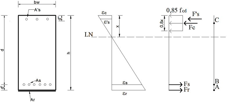
The calculation begins with the definition of the type of crack that the reinforced concrete element will present in the rupture. Hence, it is necessary to adopt the relation between the depth of the neutral axis (x) and the useful height of the element (d), since this parameter determines if it will be a fragile or ductile failure. For reinforced concrete elements with fck up to 50 MPa, NBR 6118: 2014 limits this value to 0.45 for the structure to show collapse with prior notice. Thus, the tensile stresses of the concrete (Fc), of the positive steel (Fs) and negative steel (F's) and of the structural reinforcement are calculated, applying the weighting coefficients defined by the international standards.
In which:
b w - Beam base;
h- Beam height;
d- Distance from the most compressed fiber to the center of gravity of the positive reinforcement;
d´- Distance from the most compressed (tensioned) fiber to the center of gravity of the negative reinforcement (positive);
x- Distance from the most compressed fiber to the neutral axis;
A s - Area of positive reinforcement (tension);
A´ s - Area of negative reinforcement (compression);
A r - Area of reinforcement;
ε c - Concrete deformation;
ε s - Positive reinforcement deformation;
ε´ s - Negative reinforcement deformation;
ε r - Reinforcement deformation;
F c - Resultant force from the compressed section of the concrete.;
F s - Resultant force from the tensioned section of the positive reinforcement;
F´ s - Resultant force from the tensioned section of the negative reinforcement;
F r - Resultant force from the tensioned section of the reinforcement.
After calculating the tensile stresses of the materials, it is performed the sum of the bending moment in relation to the reinforcement application (point A of Figure 3), where the reinforcement and glue thickness are neglected for their fastening. The bending moment found at this point is valid for any other location of the beam and will be pertinent to the designing if it presents a value greater than or equal to the requested one. However, if this value is much larger than the requested bending moment, the crack mode and the position of the neutral axis initially settled are not adequate because they do not lead to an economical solution.
If the value found is acceptable, it is set the resistant bending moment in relation to the cross-section points B and C in Figure 3. As in point A, these values should be matched to the requested bending moment. The equations for calculating the moments at points A, B and C are described below.
The coefficient ϕ represents the reduction factor applied only when the reinforcement is the carbon fiber. It is adopted ϕ = 0.85, as suggested by ACI 440.2R: 2008. From equations (2) and (3) we find two values for the force of reinforcement (F r ) which, by equilibrium, must be equal. This force will be used to calculate the required reinforcement area, from equations (4) and (5).
In which:
f r - It is the tensile strength of the reinforcement;
E r - It is the elasticity modulus of the reinforcement, provided by the material manufacturer;
ε r - It is the deformation of the reinforcement material, found by:
Such as:
ε r - It is the deformation of the reinforcement found by the linear behaviour of the deformations according to the position of the neutral axis (x);
ε bi - It is the pre-existing deformation in the steel located at the bottom of the beam, the result of its previous loading, as described by Machado (2002).
Also, according to Machado (2002), to know the level of tension, which will be reinforced during its application, it is necessary to identify the existing deformation in the structure to be reinforced. Therefore, the pre-existing deformation in the lower face of the beam (ε bi ) is verified. This deformation can be calculated from its permanent load when the element is strutted during the application of the reinforcement, or its entire working load, in case the strutting is not chosen. It is worth mentioning that, if the calculated resistant moment of the structural element is lower than the requested one, the position of the neutral axis is changed, and the process described above is restarted. It is, therefore, an iterative method.
4. Materials and methods
The study consists, initially, in the numerical representation of a beam with a span of 6.0m and cross section shown in Figure 4, degraded by the action of fire. Next, the two types of reinforcements studied here, steel sheets and carbon fibers, will be designed with the purpose of recovering the initial resistant capacity of the beam.

The concrete adopted for the beam under study has fck equal to 30 MPa and steel of type CA50, whose modulus of elasticity is equivalent to 210 GPa. According to the calculation methods presented in NBR 6118:2014, the structural element was designed to resist a requested bending moment of 265.7 kN.m. Attention is drawn to the kind of crack that the beam presents. It lies in the deformation domain 2, where the steel has a maximum deformation of 1%, while that of the concrete ranges from zero to its limit, which is equal to 0.35%.
In order to represent the fire's action on the beam, a numerical model was developed using the ABAQUS computational code, which allows the solution of engineering problems, including structures at high temperatures, based on the Finite Element Method theory.
The behavior of a reinforced concrete beam under fire is complex and goes beyond the reduction of the mechanical properties (strength and stiffness) of steel and concrete. There is, for example, the previously described phenomenon of spalling, which causes the cross section to lose part of the concrete thickness when it reaches the temperature range 375-425 ° C (Deeny et al., 2008). In addition, during the fire, since the steel and the concrete present different coefficients of thermal expansion, there may be longitudinal cracks in the contact between these materials.
Considering the situation presented above, for the case study presented in this work we will adopt some simplifications for the design of the reinforcement, which are described below:
The thermal numerical modeling will be used only to obtain the temperature field formed in the cross section. From the thermal gradient caused by the low thermal conductivity of the concrete, an average temperature representative of the beam heating will be calculated, which will be used to calculate the reduction of the mechanical properties of the materials.
A displacement of 1.5 cm in thickness shall be considered throughout the cross section of the reinforced concrete beam to represent the spalling.
The reinforcement will be calculated for the new cross section, admitting the decrease of the mechanical properties of concrete and steel. The requested moment that the degraded element must support corresponds to the one for which it was initially designed, that is, 265.7 kN.m.
The post-fire behavior of the reinforced concrete beam shall not be considered in the analysis. 5. It is assumed the perfect adhesion between the concrete, the framework and the reinforcement to be used.
It is not allowed changes in the ultimate deformations of concrete and steel (0.35% and 1%, respectively) with the elevation of temperature.
No additional deformation, cracking or any other manifestation will be taken into account for the calculation of reinforcement.
The effect of the thermal action on the shear strength of the reinforced concrete beams will not be considered. It is known that in normal situations, the force that takes these structural elements to failure is the flexure. Therefore, the calculation of the reinforcement presented here will be only to combat this force.
The following items will describe in detail the thermal numerical modeling and the calculation of the reinforcement for the beam under study.
5. Case study
5.1. Thermal numerical modeling
ABAQUS adopts the principle of the conservation of energy to perform its thermal analysis. Regarding the method of analysis, the transient sort was adopted in this work, in which the thermal properties of the materials and the temperature distribution vary over time. The boundary conditions required to perform a thermal analysis refer to the three mechanisms of heat transfer: convection, radiation and conduction.
The convection and radiation are inserted in the model with the commands "Surface film condition" and "Surface radiation", respectively, which are available in the Interaction function of the computational code. The application of these phenomena occurs through the creation of a surface in the structural element and insertion of the quantities, the convection coefficient (αc) for the first mechanism, and the resulting emissivity of the material (ε) and Stefan-Boltzmann constant (5,67 x 10⁻⁸ W/m² K4) for the second. Regarding conduction, it is provided for the numerical analysis the density, specific heat and thermal conductivity for concrete and steel. The value adopted for the resultant emissivity of the concrete was 0.7, and for the convection coefficient, 25 W/m² ºC.
The modeling was carried out based on the parameters and properties of the materials described in the Brazilian standard (NBR 1500, 2012) and European standard (EUROCODE 2 Part 1-2 (2004)) that deal with the behavior of reinforced concrete at high temperatures. The heating curve used to heat the structural element corresponds to the standard fire curve provided by ISO 834-1:1999. In this context, the thermal action with duration of 60 minutes was applied on the four faces of the beam with the objective of simulating a uniform heating.
This time corresponds to the minimum time that a beam, when present in a residential environment, must withstand fire, as provided in NBR 14432: 2000. With respect to the creation of the numerical model, the finite element of the solid type, DC3D8, was used to represent the concrete, and the bar element, DC1D2, for modeling the reinforcement. The insertion of the reinforcement in the concrete was done through the command embedded region that indicates to the computer code that they are positioned inside the concrete and both materials have perfect adherence. In the mesh generation, a refinement study was made, from which an automatic process was chosen which sought finite elements with a size equal to 30 mm.
It is important to note that in the computational codes, thermal numerical modeling is performed separately from the modeling in which the load of the structural element is considered. The analysis called thermo-structural, characterized by being the one in which a structural element is in a fire situation, is made by associating the results of each of the previously mentioned steps. Hence, naturally, in the numerical modeling performed in this article, which is the thermal analysis case, the possible effects caused by the load on the beam are not considered, so the reduction coefficients of the mechanical and thermal properties of the concrete and steel are not modified and correspond to those mentioned in the Brazilian and European standards. The thermal numerical results are described below.
5.1.1 Description of the thermal field
Using the parameters described above it was possible to obtain the thermal field formed in the cross section of the studied beam. In order to characterize the temperature advance along the section, six measurement points of this magnitude (T1 to T6) were selected and are indicated in Figure 5a that presents the discretized beam. Based on this assumption, the evolution of the temperatures of these points is shown in Figure 5b.

Figure 5 a) Position of temperature measuring points in the cross section; b) Evolution of the temperatures of the measuring points
As can be seen in Figure 5b, the reinforced concrete beam, even heated on all four sides, presented a non-uniform thermal field along the cross section, so that as it approached its geometric center, smaller the temperatures became. This is due to the low thermal conductivity of the concrete and the robustness of the section that promotes a differential heating of the structural element. The foregoing conclusion can be seen in Figure 6, in which the temperature variation developed in the section is illustrated for a time of 60 minutes exposure to fire.

It is important to emphasize that, as the numerical analysis was developed using the parameters (thermal properties and gas heating curve) provided by current fire standards, there will be no validation of these numerical models. This is because the experimental tests can hardly be calibrated by the normative parameters, since the heating curve usually obtained in tests differs from that of the standard fire. Moreover, since this is only a comparative study between types of reinforcement, the simplification above does not invalidate the purpose of this work.
5.2. Resistant capacity of the degraded beams
In the previous item, the reinforced concrete beam was modeled to represent its behavior in a fire situation. After obtaining the thermal field, it was possible to calculate the average temperature of the cross section that results in the reduction of the mechanical properties of steel and concrete. Prior to this calculation, as well as for the determination of the resistant capacity of the deteriorated element, a 1.5 cm thick layer of concrete was removed in every cross section for spalling representation, being the new section shown in Figure 7.

The average temperature for each section material, obtained in the thermal analysis, was 394.7ºC for the concrete and 358,5ºC for the steel. Based on the coefficients of the compressive strength reduction of the concrete (kc,θ), the yield stress (ks,θ) and the modulus of elasticity (kEs,θ) of the steel as a function of temperature described in NBR 15200: 2012 (Table 1) it was possible to reduce the mechanical properties of the materials.
Table 1 Coefficients of reduction of steel and concrete mechanical properties
| Temperature | Concrete | Steel | |
|---|---|---|---|
| kc,θ | ks,θ | kEs,θ | |
| 20 | 1 | 1 | 1 |
| 100 | 1 | 1 | 1 |
| 200 | 0.95 | 1 | 0.9 |
| 300 | 0.85 | 1 | 0.8 |
| 400 | 0.75 | 0.94 | 0.7 |
| 500 | 0.6 | 0.67 | 0.6 |
Source: ABNT NBR 15200:2012 (Adapted).
To simplify the problem, the temperature of 400ºC in both materials will be considered to reduce the mechanical properties described above. In view of this, concrete is now considered with f ck =22,5 MPa and steel, f y =470MPa and E s =147GPa.
Based on the calculation method presented by NBR 6118:2014, it can be concluded that the beam has lost 12% of its pure flexure resistant capacity, i.e., the degraded section will only withstand a requesting bending moment of 233,7 kNm which is now in deformation domain 3. As described in the initial hypothesis, the beam was subjected to a requesting bending moment of 265.7 kNm, it will need structural reinforcement.
5.3. Structural reinforcement design
In this item the necessary area of the structural reinforcement (carbon fiber and bonded-in steel sheet) is determined so that the degraded beam will again support the requested moment for which it was dimensioned. Therefore, initially the preexisting deformation in the steel (ε bi ), as a result of its initial loading, must be calculated as described in the reinforcement calculation methodology.
Assuming that the permanent load corresponds to 80% of the total load acting on the beam and that it is a distributed single load, the requested moment of the calculation, due to this load, will correspond to 212.56 kNm. Thus, from the equilibrium equations and Hooke's Law, provided by the resistance of materials, it is calculated the deformation that the steel will have in the degraded beam which in this study was equivalent to 0.25%.
Following the methodology described in item 4, in the next items will be presented the calculation of the required area for the two types of reinforcements studied. In order to obtain the most economical situation in which the resistant moment (MRd) approaches the requested one (MRd), the position of the neutral axis was changed until it was reached the equilibrium equations.
5.3.1 Carbon fibers
The carbon fiber used in the development of this study corresponds to that provided by the company MasterBrace "BASF”, it is called LAM 170/3100 "BASF", it has a square mesh of 120 mm wide, a thickness of 1.4 mm and a modulus of elasticity of 170 GPa. In Table 2, the design of the reinforcement with carbon fiber is shown in a simplified form.
Table 2 Design of carbon fiber reinforcement
| x(cm) | F c (kN) | F s (kN) | F r (kN) | σf c (kN/cm²) | A s (cm²) | F s +F r (kN) | M Rd |
|---|---|---|---|---|---|---|---|
| 14,00 | 413,10 | 492,89 | 2579,04 | 140,25 | 18,39 | 3071,93 | 197,56 |
| 15,00 | 442,61 | 492,89 | 2088,41 | 124,10 | 16,83 | 2581,30 | 210,94 |
| 16,00 | 472,11 | 492,89 | 1607,04 | 109,97 | 14,61 | 2099,93 | 224,10 |
| 17,00 | 501,62 | 492,89 | 1134,93 | 97,50 | 11,64 | 1627,82 | 237,02 |
| 18,00 | 531,13 | 492,89 | 672,07 | 86,42 | 7,78 | 1164,96 | 249,72 |
| 19,00 | 560,64 | 492,89 | 218,47 | 76,50 | 2,86 | 711,36 | 262,17 |
| 20,00 | 590,14 | 492,89 | 93,58 | 67,58 | 1,38 | 586,47 | 274,38 |
In which,
x- Position of the neutral axis;
F c - Concrete resistant force;
F s - Steel resistant force;
F r - Reinforcement resistant force;
σ fc - Tension to which the reinforcement is subject;
A s - Required area of reinforcement;
F s +F r - Sum of horizontal resistant forces of the steel and the reinforcement which, by equilibrium, must be equal to that corresponding to the resistant force of the concrete;
M Rd - Resistant moment of the reinforced beam.
With the data presented in Table 2 it can be inferred that the position of the neutral axis, for an economic design associated with a correct balance of horizontal forces (resistant force of the concrete equal to the sum of steel and reinforcement resistant forces), is located between 19 and 20 cm. Analyzing this range of values, it is accepted that the value of x=19,85cm is the one that best meets the quoted criterion. For this value, the required reinforcement area is 1.35 cm² and the resistant moment is approximately 270 kNm.
As the carbon fiber has a width of 120 mm in each lamina and it has a thickness of 1.4 mm, only one layer of this reinforcement will be adopted along the whole span of the beam.
5.3.2 Bonded-in steel sheets
The laminated steel sheet used in this study corresponds to ASTM A 572 Grade 50, 4 mm thick, for structural works. According to NBR 8800:2008, sheet A 572, with a thickness of less than 100 mm and grade 50, has a yield stress of 345 MPa and a tensile stress equivalent to 450 MPa. Similar to item 5.3.1, Table 3 demonstrates the design for the bonded-in steel sheet.
Table 3 Design of bonded-in steel sheet reinforcement
| x(cm) | F c (kN) | F s (kN) | F r (kN) | A s (cm²) | F s +F r (kN) | M Rd |
|---|---|---|---|---|---|---|
| 14,00 | 413,10 | 492,89 | 2192,19 | 73,07 | 2685,07 | 197,55 |
| 15,00 | 442,61 | 492,89 | 1775,15 | 59,17 | 2268,04 | 210,94 |
| 16,00 | 472,11 | 492,89 | 1365,99 | 45,53 | 1858,87 | 224,10 |
| 17,00 | 501,62 | 492,89 | 964,69 | 32,16 | 1457,58 | 237,03 |
| 18,00 | 531,13 | 492,89 | 571,26 | 19,04 | 1064,15 | 249,72 |
| 19,00 | 560,64 | 492,89 | 185,70 | 6,19 | 678,59 | 262,17 |
| 20,00 | 590,14 | 492,89 | 79,55 | 2,65 | 572,43 | 274,38 |
Based on the results presented in Table 3, it can be observed that the position of the neutral axis between 19 and 20 cm provides, in addition to a more economical design (MRd=Msd), a better balance of horizontal forces. From the calculations, a value of x equal to 19.3 cm is defined. This value generates a resistant moment of approximately 265.8 kNm and a required area of reinforcement equal to 2.54 cm².
In view of this, it is adopted a steel sheet with the same width of the beam and a thickness of 1 mm to be distributed along the length of the structural element.
5.3.3 Comparative analysis between carbon fiber and bonded-in steel sheet
Analyzing the presented results, it is possible to verify that the use of bonded-in steel sheet, as structural reinforcement, requires a larger area for the degraded beam to recover its resistant capacity. This is justified by the high mechanical strength of the carbon fiber.
For practical purposes, choosing the best type of reinforcement involves a number of factors, such as price, useful section increase, performance, runtime, among others. In general, the literature points to carbon fiber as the best type of structural reinforcement because, although more expensive compared to steel sheets, it has a faster execution, better performance and does not significantly increase the cross section, in addition to being corrosion resistant.
In the case study presented in this article, the increase of the cross section was similar for both reinforcements due to the low request required for the performance of the carbon fiber and the steel sheet. In view of this, and based on the available literature, it is stated that when it is necessary the expressive increase of the resistant capacity of a beam associated with a low increase of the cross section, the use of carbon fiber tends to be more advantageous when compared to the steel sheets. However, as mentioned, the choice of the best type of reinforcement should be made in a judicious way, analyzing all the parameters that influence this decision.
6. Conclusion
It has been developed a study about the comparison between structural reinforcement with bonded-in steel sheets and carbon fibers applied in fire-damaged reinforced concrete beams. The cited pathology reduces the mechanical properties of the steel and concrete, so that the resistant capacity for which the structural element is designed decreases, which requires the application of reinforcement.
Therefore, a case study was developed in which a reinforced concrete beam was modeled using the ABAQUS computational code and exposed to standard fire on all four faces during an exposure time of 60 min. From the obtained thermal field, it was possible to determine the average temperature that the constituent materials were submitted, approximately 400ºC, which was responsible for reducing its mechanical properties.
When calculating the necessary reinforcement for the beams, it was verified that the carbon fiber generated a smaller area in comparison to the bonded-in steel sheet, since the first one presents a high mechanical resistance. In general terms, it is recognised that the carbon fiber presents greater advantages with respect to the reinforcement of beams, such as speed in the execution and a not significant increase of the height of the cross section.

