


 nueva página del texto (beta)
 Inglés (pdf)
 Artículo en XML
 Referencias del artículo
 Enviar artículo por email
 Citado por SciELO
  Similares en
SciELO
Similares en
SciELO 
 Permalink
1. Introduction
Among the techniques used for the strengthening of reinforced concrete structures, we highlight the systems that use Fiber Reinforced Polymers (FRP), for presenting low weight and high tensile and corrosion strength, and the Carbon Fiber Reinforced Polymers (CFRP) that have shown significant acceptance for more than two decades due to their high values of strength, stiffness and durability, as well as the ease of installation when compared to other types of fibers (Monti and Liotta, 2007). In the specific case of flexural reinforcement of reinforced concrete beams, several researchers show that the use of sheets of CFRP is an effective methodology, highlighting the works of Rafi et al. (2008), Khan and Fareed (2014) and Hawileh et al. (2015).
However, it is important to feature that premature failures are associated with its use. In the case of flexural reinforced beams, this brittle fracture may occur due to the detachment of the carbon fiber from the concrete substrate, which may limit the increase in strength provided by the reinforcement. This mode of brittle ruin is usually associated with deficiency in the anchorage of the reinforcement system, which makes the use of additional devices recommended, such as band clipping of CFRP sheet (see Benjeddou et al., 2007; Dong et al., 2011, Kim and Shin, 2011, among others).
This work presents a series of experimental tests on reinforced concrete beams strengthened with CFRP sheets, carried out with the objective of evaluating the influence of the anchorage in the reinforcement structural performance. In addition, a large database was set up, with experimental results selected from the work of different authors. This database is used to discuss the influence of different parameters on the performance of reinforcement with CFRP sheets and to evaluate the performance of theoretical predictions of strength obtained using the recommendations presented by ACI 440-2R (2008) and fib Bulletin 14 (2001).
2. CFRP strengthened beams
2.1 Failure modes
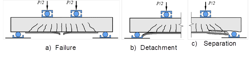
Teng et al. (2003) state that beams strengthened to flexure with CFRP sheets may exhibit brittle failure modes, for instance: by exhaustion of the strength of the CFRP (see Figure 1a); detachment of the reinforcement at the interface with the concrete (see Figure 1b); and separation of the reinforcement together with the concrete covering of the flexural reinforcement (see Figure 3c). The failure of the CFRP sheet can occur in weakly reinforced beams by flexure, being a brittle mode of failure since the CFRP presents linear-elastic behavior until the failure. The detachment of the sheet may occur due to lack of the anchorage of reinforcement, excessive cracking of the beam or, faults in its bonding process. The separation of concrete cover layer can be caused by shear strengths at the interface between concrete and CFRP due to the difference between the moduli of elasticity of these materials, which can be amplified by the corrosion of the bending reinforcement.
2.2 Flexural Strength
The behavior of a reinforced concrete beam strengthened with CFRP and subjected to bending can be expressed according to the diagram of Figure 2. In this analysis, it’s considered that the ratio of the reinforced beam framework is equivalent to the sum of the initial reinforcement rate with contribution from the reinforcement, as presented in (1).
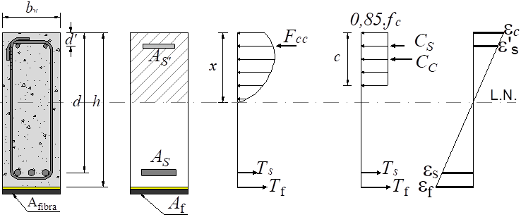
Where: ρ is the rate of the reinforcement of the beam before the strengthening; A f is the area of reinforcement applied to the beam; E f is the modulus of elasticity of the CFRP; E s is the modulus of elasticity of steel; b w is the width of the beam; h is the height of the beam.
2.2.1 ACI 440-2R (2008)
The American code ACI 440-2R (2008) presents recommendations for the sizing of reinforcement using CFRP. To determine the flexural strength of reinforced concrete beams reinforced with carbon fiber sheets, (2) - (10) are used.
Where: εfd is the limit value of fiber strain to be adopted in the sizing and verification of reinforcement to avoid premature fiber failure; n is the number of layers of CFRP; tf is the thickness of the CFRP; εfu is the ultimate strain observed in the polymer at the moment of failure; εfe is the effective strain in the CFRP; x is the position of the neutral axis; εbi is the strain found in the covering of the tensile reinforcement in the beam before the strengthen; ffe is the effective strength of the CFRP; d is the effective beam height; εs' is the strain in the compressed reinforcement; fs' is the strength in the steel of the compressed reinforcement; d’ is the centroid position of the compressed reinforcement; εs is the strain in the tensile reinforcement; fs is the strength in the steel of the tensile reinforcement; As is the steel area of the tensile reinforcement; As' is the steel area of compressed reinforcement; β1 is a coefficient that determines the approximation of the resultant compression curve of the concrete to a rectangle, being 0.85 for concrete with fc values lower than 28 MPa and there being a linear decrease of 0.05 for each 7 MPa above that limit of strength, the minimum value for such a coefficient, according to ACI 318 (2014), is 0.65; MR is the tough moment in the cross section of the beam.
2.2.2 20
The fib Bulletin 14 (2001) presents recommendations for the dimensioning of flexural reinforced beams with CFRP and adopts a calculation philosophy like that adopted by ACI 440-2R (2008). The same equations presented by the ACI are used in this document, differentiating only the following parameters: the coefficient β1 in it is called of ψ and equals to 0.8, independent of the class of strength of the concrete; and the strain limit of the fiber, which is calculated by (11), whose parameters are found by means of (12) - (14).
Where: Nfa,max is the maximum force that can be applied to the reinforcement of the beam (expressed in N); α is a reduction coefficient due to the propagation of inclined cracks, adopted as 0.9; c1 is equal to 0.64; kc is a constant that considers the compacting of the concrete during the concreting, being this value equal to 1 when the strengthening is applied in the underside of the beam and 0.67 in the upper face; kb is a geometric factor; fctm is the average tensile strength of concrete, as expressed in Eurocode 2 (2004); bf is the width of the layer of CFRP.
3. Experimental program
3.1 Characteristics of the beams
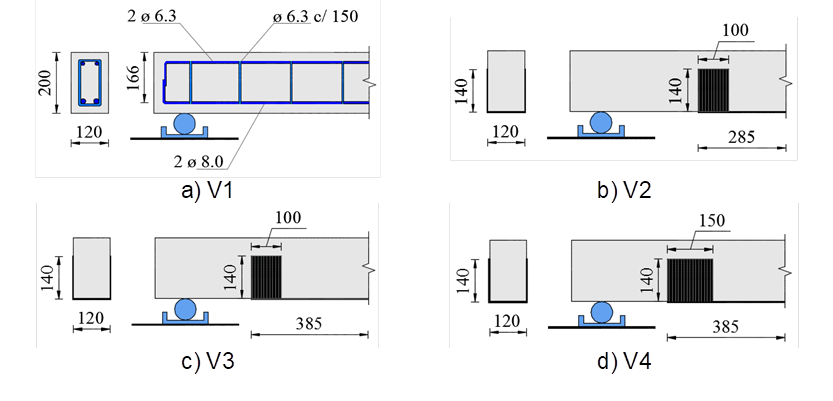
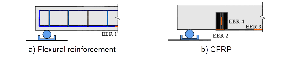
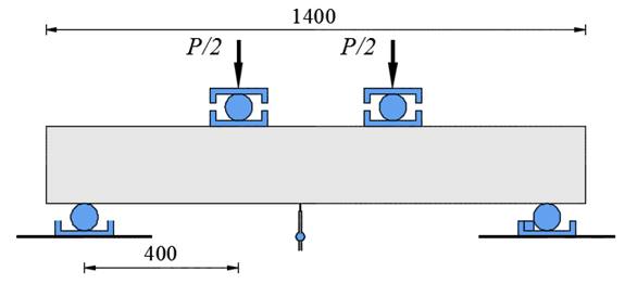
Tests were carried out on 4 reinforced concrete beams strengthened with CFRP sheets, having as variables the sheet anchorage length and width in order to evaluate their influence on both the performance and the strength of the beams. It was tested 1 reference beam without reinforcement and 3 reinforced beams with carbon fiber sheet. The rates of steel reinforcement and CFRP were kept constant. Table 1 and Figure 3 show the main characteristics of the beams. The strains in the flexural reinforcement, the reinforcement sheet and the clamping were monitored with electrical extensometers, as shown in Figure 4. Figure 5 shows the test system of the beams.
Table 1 Characteristics of the tested beams.
| Beam | l (mm) | l b (mm) | b f (mm) | A f (mm²) | t f (mm) | E f (GPa) | ε fu (%) |
|---|---|---|---|---|---|---|---|
| V1 | - | - | - | - | - | - | - |
| V2 | 100 | 285 | 120 | 19.92 | 0.166 | 230 | 2.1 |
| V3 | 385 | ||||||
| V4 | 150 | ||||||
| b w = 120 mm; h = 200 mm; d = 166 mm; A s = 101 mm²; f c = 20 MPa; a = 400 mm | |||||||
3.2 Discussion of Results
The failure mode of each of the beams tested can be visualized in Figure 6. It was observed that the reference beam failed by flexure after its longitudinal reinforcement reached high levels of strain (Figure 6a). In the V2 beam the concrete was pulled out in the zone adjacent to the clamping (Figure 6b). The V3 beam lost its strength after the fiber detachment occurred in part of the clamping contact zone (Figure 6c). However, the V4 beam failed after the detachment of the concrete covering in the region of the flexure span (Figure 6d).
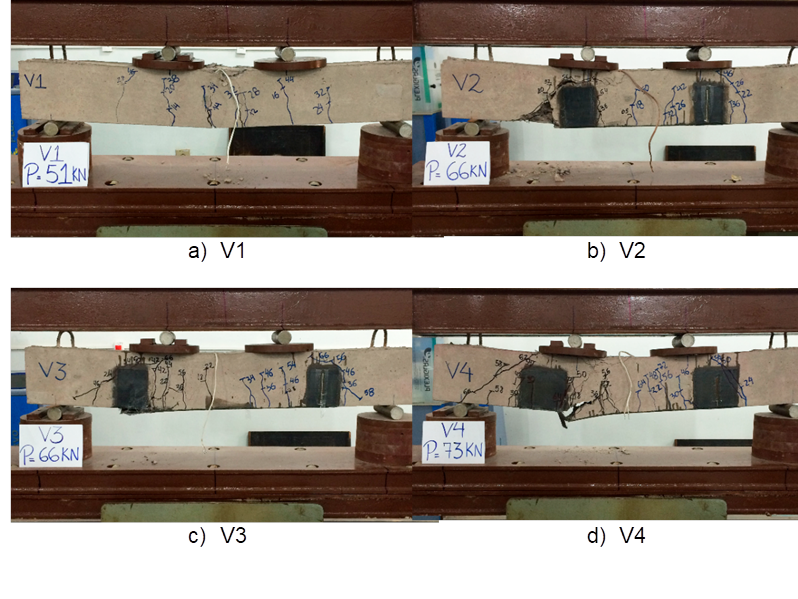
Figure 7 shows the results of strains measured in the flexural reinforcement and at different points of the PRFC. It is noticed that, in all the beams, the flexural reinforcement reached the yielding, as shown in Figure 7a. The strains in the flexural reinforcement were smaller in the beams with the sheet of CFRP for the same load levels, since the reinforcement contributed in the tensile part of the piece. In addition, it was observed that the resistant behavior of the beams with the sheet was more brittle than that of the non-reinforced beam, since after reaching the maximum strength, the readings were interrupted by the failure of the part, whereas in the beam V1, if the maximum load was reached, this loading level remained associated to a high level of strain. Figure 7b shows that both the anchoring length of the fiber and the clamping width influenced the ultimate strain of the CFRP measured in the tests, varying from 3.5 ‰ for the beam V2 to approximately 4.2 ‰ for the beams V3 and V4. In all cases, it should be noted that these values are higher than theoretically predicted by the ACI, which would be 1.9 ‰. It should be emphasized that none of the beams failed with the exhaustion of the tensile strength of the sheet of CFRP. Figure 7c shows that in all the beams the level of strain at the end of the reinforcement was smaller than that measured in the middle of the span, where the moment is maximum and that in the case of the beam V2, which failed due to the detachment of the fiber in this region, the strain limit measured was practically the same as that suggested by the manufacturer of 2.1 ‰. In Figure 7d it is possible to notice that the level of strain developed in the region of the clamping was small and that in beam V3 it clearly begins to separate before the failure.
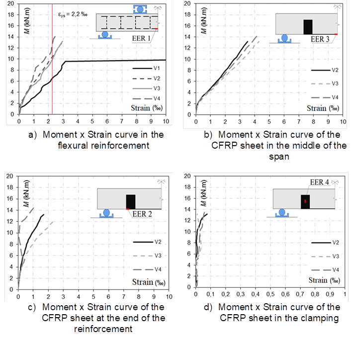
Figure 8 shows the vertical displacement curve of the beams, measured in the middle of the span. It is possible to notice that the reinforced beams presented a very similar response, showing greater rigidity than the reference beam, which failed by flexure in a ductile manner and showed large displacements when reaching the moment of yield of its flexural reinforcement. As seen, all the reinforced beams failed abruptly, with failure occurring in different regions of the CFRP.
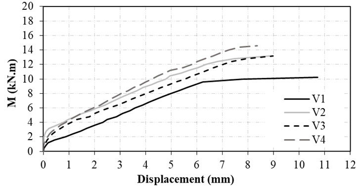
Table 2 presents the final loads of the tested beams and compares the strength of the reinforced beams with the sheet of CFRP with the reference beam (V1), in order to determine the increment of strength generated by the reinforcement. In addition, the experimental strength of the beams is compared with theoretical estimates obtained following the recommendations of the ACI and fib14. From these results, it was observed that the increase of the anchoring length of the beam V3 in relation to the beam V2 did not result in an increase of strength, and that the increase of the clamping width was responsible for the greater strength of the beam V4 in relation to the beam V3. It was also observed that the use of ACI would result in predictions of strength against safety for beams V2 and V3, while fib14 presented results in favor of safety.
4. Database
4.1 Methodology of collection and analysis of data
In addition to the experimental program, a database was collected with the results of 126 tests of 20 authors, involving flexural reinforced beams with the sheet of CFRP. As a criterion for the choice of beams, only those that failed by bending, without initial loading and externally bonded reinforcement, were selected. The objective of this data analysis is to evaluate the influence of the main variables on the flexural strength of reinforced beams with CFRP.
The analysis of the database involves the comparison of the experimental results with the theoretical estimates obtained using the ACI and fib 14. Thus, it was calculated the values of average, coefficient of variation and standard deviation of the ratio between the experimental ultimate moment and the theoretical resistant moment (M u/M Rteo), and finally, the percentage of safety results (M u/M Rteo <1) was evaluated. In order to evaluate the precision of the theoretical models, graphs are presented that compare the moment of experimental failure (M u) by the function of the predicted resistant moment (M Rteo), in order to analyze if the tendency of the obtained results approaches the ideal condition (M u=M Rteo).
As previously noted, the performance of the reinforcement with sheet of CFRP is directly related to the quality of fiber anchoring to concrete. Therefore, the beams of the database were divided into 3 groups: group 1 for situations where the bonding of the sheet stretched from the center of the beam to the support or beyond; the group 2 with beams in which the glue of the sheet did not extend to the support; and the group 3 with beams in which external devices were used to aid in reinforcement anchorage, such as screws or restrainers. It should be noted that this type of anchorage is considered by several authors as the most favorable for anchoring the CFRP sheet, since that the device is made of this same material.
Another method used was the Collins (2001) criterion, known as Demerit Points Classification (DPC), in which the values of M u/M Rteo were classified in ranges from "extremely dangerous" to "extremely conservative", with performance of the theoretical model defined as a number resulting from the sum of the products from M u/M Rteo by their corresponding score, according to the classification. Table 3 presents a summary of the characteristics of the beams of the database, as well as the symbology used by the authors to identify the figures. Table 4 shows a summary of the variables related to the reinforcement with carbon fiber sheet of the beams of the database. Table 5 presents the parameters related to Collins DPC (2001).
Table 3 Characteristics of the database beams.
| Author | No. of beams | b w (mm) | h (mm) | d (mm) | a (mm) | A s (mm²) | f ys (MPa) | f c (MPa) |
|---|---|---|---|---|---|---|---|---|
| Beber (2003) | 12 | 150 | 300 | 272 | 833 | 245 | 706 | 32 |
| Beber et al. (2000) | 8 | 120 | 250 | 219 | 783 | 157 | 565 | 33 |
| David et al. (2003) | 4 | 150 | 300 | 267 | 933 | 307 | 500 | 39 |
| Esfahani et al. (2007) | 6 | 150 | 200 | 164 | 600 | 402-626 | 350-406 | 24 |
| Breña et al.(2003) | 9 | 203 | 356-406 | 318-368 | 1065-1220 | 395 | 440 | 35-37 |
| Rusinowski et al.(2009) | 5 | 200 | 300 | 262 | 1300 | 402 | 527 | 64-70 |
| Toutanji et al. (2006) | 7 | 108 | 158 | 127 | 560 | 142 | 427 | 49 |
| Barros et al. (2007) | 6 | 120 | 170 | 141-145 | 300 | 39-99 | 627-788 | 44 |
| Gamino (2007) | 14 | 75 | 150 | 120 | 550 | 62 | 640 | 45 |
| Zhang et al. (2006) | 4 | 120 | 250 | 224 | 750 | 226-402 | 335 | 23 |
| Spadea et al. (2000) | 2 | 140 | 300 | 266 | 1800 | 402 | 435 | 30 |
| Alagusundaramoothy et al.(2003) | 12 | 230 | 380 | 342 | 1830 | 981.75 | 414 | 31 |
| Ferrari (2007) | 3 | 170 | 350 | 300 | 950 | 254.4 | 548 | 35-38 |
| Dias et al. (2002) | 5 | 120 | 180 | 160 | 720 | 100.5 | 533 | 41 |
| Balaguru e Kurtz (2001) | 3 | 200 | 300 | 255 | 1000 | 258 | 447 | 47 |
| Vieira et al. (2016) | 8 | 120 | 245 | 220 | 800 | 157-245 | 500 | 44 |
| Bilotta et al. (2015) | 2 | 120 | 160 | 135 | 925 | 157 | 590 | 21 |
| Garcez (2007) | 2 | 150 | 300 | 270 | 950 | 245.4 | 578 | 41.4 |
| Juvandes (1999) | 9 | 75-150 | 150 | 130 | 605-650 | 14-226 | 192-507 | 20-45 |
| Chahrour e Soudki (2005) | 5 | 150 | 250 | 219 | 750 | 402.1 | 400 | 39 |
Table 4 Strengthening variables of the beams.
| Author | No. of beams | No. of layers | b f (mm) | t f (mm) | A f (mm²) | E f (GPa) | e fu (‰) |
|---|---|---|---|---|---|---|---|
| Beber (2003) | 12 | 1-6 | 50-150 | 0.1-1.4 | 10-140 | 240 | 12-14 |
| Beber et al. (2000) | 8 | 1-10 | 120 | 0.011 | 1.3-13.2 | 230 | 15 |
| David et al. (2003) | 4 | 2-4 | 50 | 1.2 | 120-240 | 150 | 15 |
| Esfahani et al. (2007) | 6 | 1-2 | 100-150 | 0.176 | 17.6-52.8 | 237 | 12 |
| Breña et al.(2003) | 9 | 1-2 | 50-100 | 0.165-1.2 | 16.5-104 | 62-230 | 12-16 |
| Rusinowski et al. (2009) | 5 | 1-2 | 50-120 | 1.4 | 140-168 | 155-300 | 9-15 |
| Toutanji et al. (2006) | 7 | 3-6 | 102 | 0.165 | 50.5-101 | 110 | 6 |
| Barros et al. (2007) | 6 | 1-3 | 9.6-80 | 0.1-1.4 | 13.4-40.3 | 158.8-240 | 15-17 |
| Gamino (2007) | 14 | 1-2 | 75 | 0.11-0.13 | 8.2-16.5 | 230-235 | 15 |
| Zhang et al. (2006) | 4 | 1-2 | 120 | 0.11 | 13.3-26.6 | 235 | 14.27 |
| Spadea et al. (2000) | 2 | 1 | 80 | 1.2 | 96 | 152 | 15.1 |
| Alagusundaramoothy et al. (2003) | 12 | 1-3 | 76-203 | 1.4-4.7 | 36.4-975 | 48-228 | 11.5-15 |
| Ferrari (2007) | 3 | 1-3 | 16.5 | 0.17 | 2.8-8.4 | 50 | 13 |
| Dias et al. (2002) | 5 | 1-2 | 20-70 | 0.1-1.4 | 15.5-28 | 200-240 | 11-15 |
| Balaguru e Kurtz (2001) | 3 | 2-5 | 152 | 0.071 | 21.6-54 | 200 | 6 |
| Vieira et al. (2016) | 8 | 2-5 | 100 | 0.166 | 33.2-83 | 230 | 21 |
| Bilotta et al. (2015) | 2 | 1-2 | 40 | 1.4 | 56-112 | 171 | 12 |
| Garcez (2007) | 2 | 1-2 | 150 | 0.165 | 247-49 | 227 | 15 |
| Juvandes (1999) | 9 | 1 | 50 | 1.2 | 60 | 155 | 19 |
| Chahrour e Soudki (2005) | 5 | 1 | 100 | 1.2 | 120 | 155 | 19 |
Table 5 Collins criterion.
| M exp/M Rteo | Classification | Penalty |
|---|---|---|
| < 0.50 | Extremely Dangerous | 10 |
| (0.50 - 0.65) | Dangerous | 5 |
| (0.65 - 0.85) | Low Safety | 2 |
| (0.85 -1.15) | Proper Safety | 0 |
| (1.15 - 2.00) | Conservative | 1 |
| ≥ 2.00 | Extremely Conservative | 2 |
Finally, were prepared graphs which relate the experimental strength of the beams to the predicted theoretical failure (M u/M Rteo) according to the number of layers of CFRP sheets, as well as the reinforcement ratio after strengthening in relation to the initial reinforcement (ρ r/ρ). The purpose of these charts is to analyze if the hypotheses adopted by the theoretical models present adequate correlation with the existing experimental evidence.
4.2 Discussion of Results
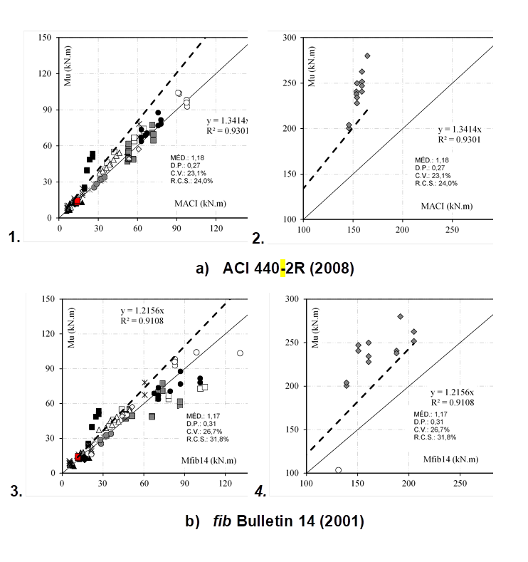
Figure 9 shows the graphs that confront the experimental strength of the database with the theoretical predictions, including in red, the experimental results tests of this research. It was observed that the two theoretical models presented similar performance in relation to the average of the results, but with fib 14 showing greater dispersion and higher percentage of results against safety. Moreover, the tested beams fit well in the trend of results observed for the larger universe generated by the database.
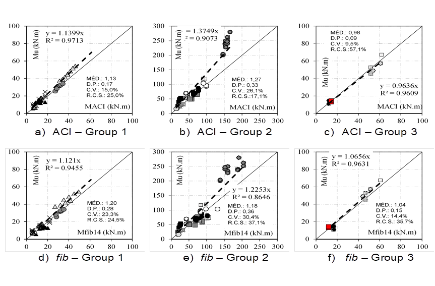
In order to evaluate the influence of the type of anchorage of the reinforcement with CFRP in the performance of the theoretical predictions, Figure 10 divides the general data presented in Figure 9, classifying them by type of anchorage in 3 distinct groups. For group 1, ACI presented an average closer to 1.0, as well as a lower dispersion of results and approximately the same number of values against safety, when compared with fib 14. In group 2, this behavior was reversed, and fib 14 showed lower average, but still with greater dispersion and greater percentage of results against the safety. For the beams of group 3 the theoretical methods presented similar performance, with the ACI showing again less dispersion
As seen, using Collins criterion (2001), it is possible to establish scores for the two recommendations, based on the sample space of the collected database, as shown in Figure 11. It is observed that the ACI presents a lower penalty according to the criterion adopted.
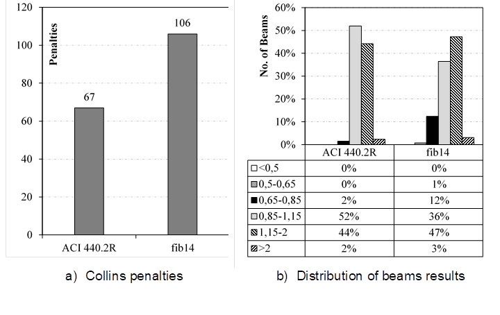
Figure 12 analyzes the influence of the number of layers of CFRP on both reinforcement performance and theoretical methods. It is noticed that there is a trend of more conservative results as the amount of layers increases, which is justified by the fact that both recommendations limit the strain of CFRP. For the ACI, this trend is slightly higher, since in its equation the number of layers is used, which penalizes the strength estimation of reinforced beams with a high number of layers. In contrast, in fib 14 this factor is not considered.
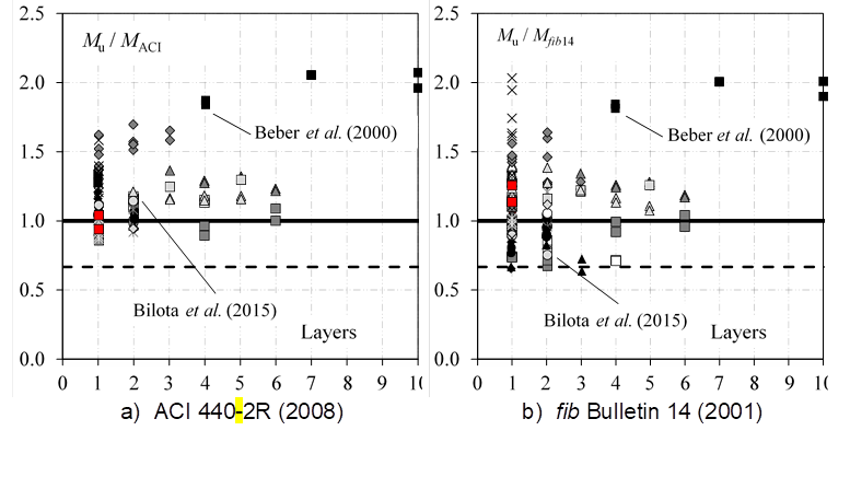
Figure 13 shows the influence of the proportion between the reinforcement ratio after the strengthening and the flexural reinforcement ratio (ρ r/ρ). There is a trend of less conservative results as ρr / ρ increases, and for values above 1.4, ACI tends to stabilize this trend, avoiding estimates of strength against safety. However, the same was not observed for fib 14, whose predictions approached the dashed line, which expresses the limit of the design strength.
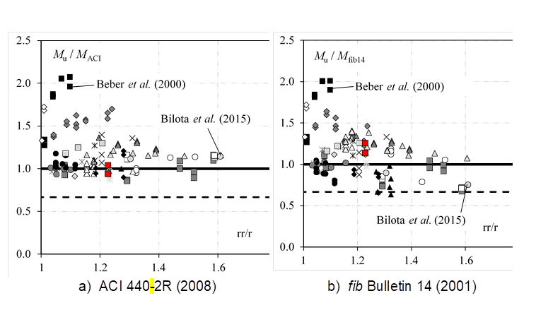
Figures 12 and 13 show that the number of layers of CFRP is not necessarily a parameter that should be penalized in the prediction of strength of flexural reinforced beams with sheets of CFRP as defined by the ACI. This is evident from, for example, the results of Beber et al. (2000), who tested beams with up to ten layers of CFRP sheets and obtained good performance, and those of Bilota et al. (2015), whose beams tested had only one or two layers of CFRP and showed much lower performance. By analyzing Figure 13, the beams of Beber et al. (2000) present low values of ρ r/ρ while those of Bilota et al. (2015) presented extreme values within the beams of this database, evidencing that ρ r/ρ is a fundamental parameter to be taken into consideration in the design.
5. Conclusion
In order to observe the influence of reinforcement anchorage with CFRP on the behavior of beams resisting to flexure, an experimental study was carried out, involving tests on 4 reinforced concrete beams, varying the anchorage criteria of the carbon fiber sheets. In addition to the experimental approach, a database with results from several authors was used to evaluate the influence of different parameters on the strength of reinforced beams to flexion with CFRP sheets. These data were also used to discuss the performance of the theoretical methods proposed by fib Bulletin 14 (2001) and ACI 440-2R (2008).
As for beam tests, it was observed that the clamping width had a greater influence on the flexural strength of the reinforced beams with CFRP sheet, since the V4 beam presented the greatest strength in relation to the others, even though the anchoring length was identical to the one of the beam V3. The beams V2 and V3 presented the same values of strength, although the beam V3 presented a greater length of anchorage between them. Another important point is that, even with the strength additions of the reinforced beams in relation to the reference, the beams with CFRP sheet have failed prematurely. Finally, it was observed that the limit values of strain of the CFRP sheet assumed by the manufacturer are very conservative in face of the experimental results recorded in this research.
As for the evaluation of the theoretical models, it is verified that both the fib 14 and the ACI presented conservative results in relation to the M u/M Rteo ratio, which in practice should guarantee predictions of strength in favor of safety in most cases. It was also observed that the procedure of reducing reinforcement efficiency by means of limitations on CFRP strains, although generally in favor of safety, may become excessively conservative in cases of reinforcement where CFRP anchorage is performed properly. Finally, it is emphasized that among the evaluated parameters that affect the flexural strength of beams with CFRP sheets, it is worth noting that the ratio ρ r/ρ was more relevant than the number of layers of CFRP sheets, considering the data of this database.

