


 nueva página del texto (beta)
 Inglés (pdf)
 Artículo en XML
 Referencias del artículo
 Enviar artículo por email
 Citado por SciELO
  Similares en
SciELO
Similares en
SciELO 
 Permalink
1. INTRODUCTION
As part of a recent reform of the energy sector in Mexico, the federal government is required to purchase unproductive properties and buildings from the private sector. Many of these have been abandoned for decades and exhibit high degrees of degradation due in part to accelerated corrosion phenomena resulting from lack of maintenance and exposure to aggressive environments.
Corrosion of reinforced concrete structures is a serious problem, particularly in industrial environments. It can manifest as intense pathological signs which can lead to critical problems in function, safety, excessive rehabilitation and service costs and loss of appearance; indeed, depending on the degree of damage, it can put human life at risk (Helene, 2003; Sulaimani 1992, Andrade 1992; del Valle et al., 2006).
Many of the properties to be acquired by the federal government are petroleum industry installations. Restoring these to productive levels of functioning will require rehabilitation. The causes for corrosion-related failures will need to be investigated as well as the complex relationship between the physical, chemical and mechanical properties of the concrete and steel reinforcement.
The present study responds to the need to rehabilitate and return to operation reinforced concrete towers in petroleum industry installations in the southern portion of the state of Veracruz, Mexico. These are a vital asset in this industry, which is economically significant in the region. The towers were evaluated with an emphasis on durability. This involved destructive and non-destructive assays, visual inspection using an aerial drone, and electrochemical, chemical and mechanical tests. These evaluations are discussed and a structural diagnosis presented highlighting the mechanisms that intensified corrosion. The final objective is to identify the corrective measures needed to extend the use life of these existing assets.
2. INSPECTION PLAN
2.1 Preliminary inspection
A survey was done of the structure, the exposure environment and damages. Due to the tower’s structural complexity and dimensions, images were taken of its elements. Visual survey was done and images taken using an aerial drone (Phantom 4), following programmed schemes as indicated in the DURAR Manual (Troconis del Rincón et al., 1997).
2.2 Detailed inspection
Premature failures in concrete structures are mainly due to lack of quality control and incorrect construction, repair and rehabilitation procedures (DURACON, 2007). A series of trials and measurements are needed to collect data to identify the causes and the proper stage of prevention. This data is used for problem evaluation, and to define the nature and mechanism of corrosion in the case at hand.
2.2.1 Electrochemical Evaluation
Steel position was detected with a wall scanner and electrochemical measurements taken. Current measurement (Ecorr vs. Cu/CuSO4) was done following the guidelines in ASTM C876-09 (2009) and NMX-C-495-ONNCCE-2015 (2015). Corrosion rate (icorr) was measured with the polarization resistance technique, using a GECOR 10 (Feliú et al., 1993) and according to NMX-C-501-ONNCCE-2015 (2015). The resulting data served to clearly define points of active corrosion in the structure.
2.2.2 Physicochemical Evaluation
Cores were extracted from the structure to directly test concrete quality and its potential to corrode the reinforcement. Assays were done of carbonation depth (NMX-C-515-ONNCCE-2016, 2016), chloride concentration (ASTM C114-05, 2005), and sulfate chemical attack. Concrete resistance to simple compression was tested with a hardened concrete core test (NMX-C-083-ONNCCE 2010, 2010).
3. RESULTS AND DISCUSSION
The tower in question is exposed to an aggressive environment, classified as B2 according to the Federal District Complementary Technical Guidelines (Normas Técnicas Complementarias de Distrito Federal - NTC-DF). This classification is based on its location in the midst of large bodies of marine waters: Laguna de Pajaritos is 700 m north and the Coatzacoalcos River is 600 and 2700 m east. It is also exposed to air containing industrial gases originating in a petrochemical complex immediately to the south (Figure 1). In addition, climate in the zone is humid tropical with a rainy season from June to September. Rainfall is highest during August and September. Annual rainfall percentage varies from 6 to 10.5% compared to the driest month of the year.

The studied structure is a cylindrical tower (23 m diameter x 70+ m high). The walls are 30+ cm thick and built of concrete reinforced with AISI 1018 steel. Aggregate is silicate sand and thick quartz gravel. Based on its Mohs scale value (7) and the prevalence of SiO2 in its chemical structure, quartz has high hardness. However, aggregate particle shape is rounded, providing weak traction in the concrete mass. Fifty years of service and its location in an industrial-marine environment have caused the tower to develop a combination of almost imperceptible and quite evident damage.
3.1 Visual inspection with drone
An aerial drone was used to facilitate damage survey due to structural complexity, limited access to high areas and time concerns. An autonomous mission was designed using a flight plan based on sequential GPS points along the tower’s four vertical surfaces (north, east, south and west). Drone cruise speed was controlled such that high quality images were taken in areas with visible structural damage. These were converted into two-dimensional maps and areas with the greatest visible damage marked (Figure 2).

Figure 2 Two-dimensional map of drone images. Areas of major visible damage delimited by green lines.
Previous, localized repairs are clearly visible in the images. Since these were probably not done adequately, they may have accelerated deterioration processes in the concrete-steel system (Figure 3 and 4). There are also areas of concrete detachment and spalling, exposed steel reinforcement, diminished section of the reinforcement and cracks ranging in length from approximately 0.50 m to 5.00 m and in width from 3 mm and up.
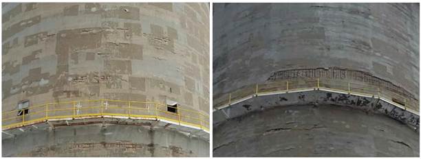
Figure 3 Exposed steel reinforcement, corrosion, concrete spalling and multiple rectangles indicating the sites of previous localized repairs.

Figure 4 Detail of localized repairs in which the more recent concrete has separated from the original concrete, causing occasional spalling and anodic zones favoring formation of corrosion cells.
Twelve study zones were then located on the structure and analyses done at these locations: linear polarization resistance using a guard ring to restrict the current (Andrade et al., 2004); half-cell potentials; and chemical tests to measure the carbonation profile and chlorine and sulfate concentrations. A test was also done of resistance to compression and the cover thickness measured with a wall sensor. Test zones were assigned keys indicating their locations (Table 1).
3.2 Detailed Inspection
3.2.1 Resistance to simple compression (f’c)
Overall f’c values were less than 250 kg/cm2 (Table 2), and in test zone U2-P1-P04 values were less than 50% of the recommended value (350 kg/cm2; NTC-DF, 2008). These values are indicated for exposure to a B2 environment, that is, member surfaces in contact with the soil and exposed to aggressive exterior environments.
Table 2 Results of electrochemical, chemical and physical tests.
| Location Code | U2-NP-P01 | U2-P1-P02 | U2-P1-P03 | U2-P1-P04 | U2-P1-P05 | U2-NP-P06 |
|---|---|---|---|---|---|---|
| Orientation | West | South | South | South | South | North |
| Height from base of structure (m) | 0 | 16 | 16 | 16 | 16 | 0 |
| Resistance to Simple Compression f’c (kg/cm2) | 246.09 | --- | 181.30 | 114.92 | --- | |
| Minimum resistance for concretes exposed to sulfates = 350 kg/cm 2 (NTC-DF, 2008) | ||||||
| Chloride Concentration at 3 cm depth (% pp concrete weight) | --- | --- | 0.05 | 0.039 | --- | 0.079 |
| Chloride Threshold = 0.11% pp concrete (P. Castro-Borges, 2013) in marine environment | ||||||
| Chloride Concentration at 3 cm depth (% pp in concrete weight) | --- | --- | 0.65 | 0.41 | --- | 0.81 |
| Maximum admissible concentration = 0.45 % pp concrete (Andrade et al. 1998) | ||||||
| Sulfates Concentration at 3 cm depth (% pp concrete) | 19.35 13.37 | --- | 21.77 | 46.09 | --- | --- |
| Corrosion Potential (mV vs. Cu/CuSO4) | >-200 | >-200 | >-200 | <-350 | >-200 | >-200 |
| Corrosion rate (µA/cm2) | 0.1 - 0.5 | > 1 | 0.1 - 0.5 | > 1 | > 1 | 0.1 - 0.5 |
| Moderate | Very High | Moderate | Very High | Very High | Moderate | |
| Average cover (mm) | 30.5 | 38 | 34.5 | 34.5 | 28 | 36 |
| Minimum cover in B2 environment = 45 mm (NTC-DF, 2008) | ||||||
| Average rebar diameter (mm) | 17.9 | 17.9 | 16.9 | 19.5 | 19.6 | 24.9 |
| Location Code | U2-NP-P07 | U2-NP-P08 | U2-P2-P09 | U2-P2-P10 | U2-P3-P11 | U2-P3-P12 |
| Orientation | South | East | East | South | South | East |
| Height from base of structure (m) | 0 | 0 | 45 | 45 | 60 | 60 |
| Resistance to Simple Compression f’c (kg/cm2) | 164.57 | 186.89 | --- | --- | --- | --- |
| Minimum resistance for concretes exposed to sulfates = 350 kg/cm 2 (NTC-DF, 2008) | ||||||
| Chloride Concentration at 3 cm depth (% pp concrete weight) | 0.03 | --- | 0.037 | --- | 0.032 | --- |
| Chloride Threshold = 0.11% pp concrete (P. Castro-Borges, 2013) in marine environment | ||||||
| Sulfates Concentration at 3 cm depth (% pp concrete) | 0.38 | --- | 0.25 | --- | 0.30 | --- |
| Maximum admissible concentration = 0.45 % pp concrete (Andrade et al. 1998) | ||||||
| Depth of Carbonation (mm) | 11.11 | 13.42 | --- | --- | --- | --- |
| Corrosion Potential (mV vs. Cu/CuSO4) | -200 a -350 | >-200 | >-200 | -200 a -350 | >-200 | >-200 |
| Corrosion rate (µA/cm2) | 0.1 - 0.5 | 0.5 - 1 | > 1 | > 1 | 0.5 - 1 | 0.5 - 1 |
| Moderate | High | Very High | Very High | High | High | |
| Average cover (mm) | 39 | 50 | 22 | 36.5 | 30.5 | 27.3 |
| Minimum cover in B2 environment = 45 mm (NTC - DF, 2008) | ||||||
| Average rebar diameter (mm) | 21.1 | 20.3 | 20.9 | 30.6 | 22.5 | 20.4 |
3.2.2 Depth of Carbonation
In some samples the depth of carbonation was notable. For example, in U2-P1-P04 a clear colorless zone was visible after phenolphthalein application (Figure 5). This indicates a considerable drop in concrete pH that extends to the depth of the rebar (Table 2). Severe damage is also present from cracks running parallel to the wall surface.

3.2.3 Sulfates concentrations
At the concrete surface, this parameter varied from 0.25 to 1.0% pp concrete content, and at 3 cm depth it varied from 0.50 to 0.80% pp concrete content (Figure 6). These are considered high values since the limit is 0.40% pp concrete content. Nearby sources of high sulfate levels include marine waters, industrial gases and the water in adjacent cooling towers. Sulfate attack of concrete components can cause formation of ettringite and plaster.

3.2.4 Chlorides concentration
Chlorides levels have not reached concentrations which could cause corrosion problems in the steel reinforcement and therefore do not seriously threaten structure integrity (Table 2) (Troconis et al., 1997; DURACON, 2006; DURACON, 2007).
3.2.5 Corrosion rate
Non-destructive tests of corrosion rate were run even though areas of exposed steel were quite evident and rebar corrosion was obvious. Values for this parameter were moderate to very high in most cases (Table 2), with values near 5 (A/cm2 (Figure 7).

The very high corrosion rate values may have been caused by localized repairs done with uncompacted materials, which cause cracks and spalling between the new and pre-existing concrete. This is a very common effect at the concrete-steel interface in real structures. It arises from the “top-bar” effect in which adherence to the steel reinforcement decreases in the cover, particularly in thick concrete with inadequate compaction (P.R. Jeanty et al., 1988; A. Castel, 2006). It can also result from corrosion caused by galvanic current within the macrocell. This is caused by an electric connection between rebar exposed to different electrochemical surroundings, that is, passive steel in recently repaired zones and active steel in carbonated zones (J. Gulikers and M. Raupach, 2006; J. Warkus and M. Raupach, 2006). High galvanic currents result which lead to high corrosion levels according to RILEM recommended levels (A. Nasser et al., 2010).
System electrolyte characteristics are vital to identifying the elements needed for aggressive agent contamination and thus to understanding the corrosion mechanisms occurring in the studied structure. The studied concrete tower is located inside a petrochemical plant and adjacent a series of cooling towers. The main mechanism for lowering water temperature in these towers is partial evaporation, which causes a gradual decrease in the quality of the circulating water. It also leads to a continuous increase in chemical compound concentration within the condenser system, and constant emission of sulfate solutions.
Sulfate ion ingress and low compression resistance values are two important conditions that can induce degradation of structural properties in the studied structure. Sulfate attack is known to be quite complicated (E.F. Irassar, 2009), although there are some principal factors that affect the evolution of concrete properties, such as sulfate solution concentration, exposure to high temperatures and low concrete pH (J. Skalny, 2002). All three of these factors were present in the studied structure. Indeed, the sulfates concentration considerably exceeded the proposed maximum concentration (C. Andrade, 1998), possibly leading to formation of ettringite and plaster. This could have accelerated concrete degradation as the products of concrete hydration and the sulfate ion solution caused expansion and cracking (C. Yu et al., 2015; F. Bellmann et al., 2006). After exposure to soluble sulfates a concrete matrix can soften or its overall porosity increase, thus reducing structure durability.
3.3 Rehabilitation-reinforcement proposal
After the inspection, recommendations were made to immediately begin repair, rehabilitation and reinforcement. A general description is provided below, but a full account is contained in the corresponding executive report. Increasing the structure’s residual use life will require that the entire tower be addressed to prevent the creation of zones vulnerable to galvanic effects.
Preliminaries
Deteriorated and/or contaminated concrete should only be removed from anodic zones. Steel rebar needs to be cleaned and the substrate prepared following official guidelines (NMX-C-518-ONNCCE-2016, 2016). If deemed necessary after evaluation, rebar should be replaced.
Stage 1
The high corrosion rate results suggest the presence of zones in which loss of steel reinforcement section is advanced. In places where the decrease in original nominal diameter exceeds 10% the structure needs to be reinforced through substitution of the damaged rebar with rebar of the original diameter and with the same yield point (fy) to meet applicable regulations (NMX-B-457-CANACERO-2013, 2013). Repair sequence and geometry must meet the guidelines in the Rehabilitar network manual (Helene, 2003).
Stage 2
Due to the structure’s geometrical condition and the difficulty of building centering and applying spray concrete at high altitudes, section recovery is best done using prepared structural repair mortar containing sulfate resistant (RS) Portland cement complying with applicable regulations (NMX-C-414-ONNCCE-2014, 2014; NMX-C-418-ONNCCE-2015, 2015). It will need to be sufficiently fluid to allow for manual application.
Stage 3
To reduce the probability of corrosion in repaired areas, calcium nitrate corrosion inhibitor will need to be applied according to ASTM C494 / C494M-17 (2017).
Stage 4
Low resistance to compression in the structure’s concrete will require reinforcement of the base with carbon fiber reinforced polymer (CFRP) up to the catwalk 1 (P1) level. This system will increase confinement, and resistance to shear force and external loads (e.g. winds and earthquakes), without compromising structure ductility (ACI-440R-07, 2007).
Stage 5
A chloride-impermeable anti-carbonation covering will need to be applied with the capacity to bridge cracks and including chemical components complying with ASTM C494 / C494M-17 (2017). If cracks appear they should be covered since these are the primary point of contaminant ingress.
4. CONCLUSIONS
Use of an aerial drone for inspection of reinforced concrete is a powerful tool allowing visual examination of otherwise inaccessible areas.
Carbonation is the primary mechanism of corrosion in the studied structure. The high CO2 concentration and high relative humidity in the surrounding environment have reduced concrete pH and generated depassivation of the steel reinforcement.
Sulfate emissions in the surrounding industrial environment and their sulfate deposition on the structure’s concrete walls has caused a notable decrease in mechanical resistance. This is clearly visible in the form of cracks and spalling.
Previous localized repairs accelerated corrosion damage in adjacent zones by creating galvanic cells.
Low mechanical resistance values in the concrete and high corrosion rate values in different zones of the structure have compromised its structural integrity. This can pose a safety risk for personnel working in the area and therefore requires immediate rehabilitation and reinforcement.
The five-stage repair proposal presented here can be expanded into a full structural repair executive project.

