


 text in
  English (pdf)
 Article in xml format
 Article references
 Send this article by e-mail
 Cited by SciELO
  Similars in
SciELO
Similars in
SciELO 
 Permalink
Introduction
The use of precision irrigation systems and their adequate design, management and scheduling plays a vital role in ensuring water application in the right place, with the right amount, at the right time. However, these practices are still under research and require a lot of experimental work, studies, and analysis to determine their viability and applicability (Al-Karadsheh, Sourell, & Krause, 2002). When irrigation engineers design an irrigation system, they try to maximize irrigation efficiency which is defined as the ratio of the volume of water that is taken up by the crop to the amount of irrigation water applied (American Society of Agricultural Engineers [ASAE], 1996). Subsurface drip irrigation (SDI) systems have the potential to increase that efficiency. A well-designed SDI system can reduce the volume of applied water by about 22 %, while increasing the yield by 7 %, compared to using a center pivot sprinkler system (Alam, Trooien, Dumler, & Rogers, 2002).
First SDI systems were applied to row crops such as corn or cotton where driplines were placed 8-10 cm below the surface of alternate rows. This allowed farm equipment such as tractors with cultivators and fertilizer or pesticide applicators to traverse the rows which did not have driplines under them in a “controlled traffic” system. As the technology continued to evolve, farmers became interested in utilizing SDI on “extensively” grown crops which are not planted in rows but are sown continuously throughout the field (Slack & Liga, 2010). One such extensively grown crop in the US is the forage crop alfalfa (Medicago sativa L.) which has rooting depths of up to 2 m. This crop has been increasing steadily in 13 western states of the U.S., and more than 404 686 ha have been added during the last decade (Alam, Trooien, Rogers, & Dumler, 2002).
Alfalfa is harvested as frequently as every two weeks, and the harvest operation requires a tractor and other heavy equipment to be driven over much of the surface of the field. Thus, dripline cannot be placed so close to the soil surface that the surface becomes wetted, or the tractor would at best leave deep damage in the field or at worst become “stuck”. A practical alternative has been to place the dripline at a depth high enough that the soil surface will not become wetted but is still shallow enough to deliver water to the plant roots. Up to this point in time, appropriate depths for such systems have been determined by “trial and error” for each new soil and equipment condition (Slack & Liga, 2010).
The general objective of this study was to determine a suitable placement depth of SDI driplines using well-established modeling techniques and classical soil mechanics theory. The specific objectives were to determine the vertical extent of the wetted zone above SDI tubes in three different soils, Sandy Clay Loam (SCL), Clay Loam (CL) and Loam (L). An additional objective was to determine the increased stress at specific depths due to the weight of a farm tractor on the soil surface, and to use this information together with soil strength properties to determine the appropriate depth of placement of drip tubes. Finally, the ultimate objective is to ensure that soil failure does not occur when the tractor is driven over the drip tubing while irrigation is in progress. Another result of the modeling exercise was the determination of the lateral extent of the wetted zone which can be used to determine the appropriate lateral spacing between drip line tubing.
Materials and methods
In this study, the two-dimensional module of the HYDRUS-2D/3D package (Simunek, van Genuchten, & Sejna, 2006, 2008) was used to determine the wetting pattern from a subsurface drip emitter for three soil types typically found in Southern California (Table 1) with an irrigation time of twelve hours and a frequency of every three days. Then, classical soil mechanics theory was applied to calculate the increase in soil stress at different depths due to a load on the surface from a typical farm tractor used in harvest operations. This information was then used in conjunction with soil strength properties such as shear strength as a function of soil moisture content to determine the minimum permissible depth of placement of drip line tubing to ensure that soil failure does not occur. The lateral extent of the wetting pattern at the end of irrigation was used to determine the maximum spacing at which an SDI system will provide adequate crop irrigation throughout the field in a particular soil
Table 1 Physical properties of the soil types.
| Properties | Sandy clay loam | Clay loam | Loam |
|---|---|---|---|
| Sand (%) | 60.0 | 30.0 | 40.0 |
| Silt (%) | 15.0 | 35.0 | 40.0 |
| Clay (%) | 25.0 | 35.0 | 20.0 |
| Bulk density (kg·m-3) | 1 620 | 1 560 | 1 510 |
| Saturated moisture content (%) | 43.0 | 48.0 | 46.0 |
| 50 % moisture content | 5.00 | 7.00 | 7.00 |
| Field capacity (90 % saturated) | 27.0 | 36.0 | 28.0 |
| Saturated conductivity (cm·h-1) | 1.13 | 0.43 | 1.55 |
| Angle internal friction (degrees) | 32.5 | 25.0 | 30.0 |
| Cohesion compacted (kPa) | 61.78 | 82.37 | 74.53 |
| Cohesion saturated (kPa) | 14.70 | 14.70 | 14.70 |
| Cohesion 90 % saturated (kPa) | 12.74 | 12.74 | 12.74 |
Based on the data in Table 1, a relationship between soil cohesion and moisture was established for the three soil types (Figure 1).

HYDRUS-2D is a two-dimensional finite element model that provides a numerical solution of the Richards equation (Equation 1) to simulate soil moisture and water flow in unsaturated soils (Kandelous et al., 2012).
Where θ denotes the soil volumetric water content (L3·L-3), K(h) is the unsaturated hydraulic conductivity (L·T-1), x and z are the coordinates (horizontal and vertical) (L), S(h) is a sink term (L3·L-3·T-1) for the plant root water uptake, h signifies the soil water pressure head (L), and t is time (T).
A solution of Equation (1) requires characterization of the soil hydraulic properties, as defined by the soil water retention [θ(h)] and unsaturated hydraulic conductivity function [K(h)]. The constitutive relationships of van Genuchten-Mualem (van Genuchten, 1980) were used and represented the effective saturation (S e ) by:
and
where θ s and θ r represent the saturated and residual water content (L3·L-3), respectively, K s is the saturated hydraulic conductivity (L·T-1), α VG (L-1), n and l are shape parameters, and m = 1 − 1/n.Table 2 lists the hydraulic function parameter values of the soils used and included in the HYDRUS-2D program.
Table 2 Soil hydraulic function parameters for used soils and included in HYDRUS-2D.
| Soil type | Θ r (cm3·cm-3) | Θ s (cm3·cm-3) | αVG (cm-1) | n | K s (cm·day-1) | l |
|---|---|---|---|---|---|---|
| Clay loam | 0.095 | 0.41 | 0.019 | 1.31 | 6.24 | 0.5 |
| Loam | 0.078 | 0.43 | 0.036 | 1.56 | 54.96 | 0.5 |
| Sandy clay loam | 0.1 | 0.39 | 0.059 | 1.48 | 31.44 | 0.5 |
The spatial distribution of the plant roots of alfalfa exert a strong influence on soil water flow, root water uptake, and deep drainage. Therefore, it primarily determines deep percolation and actual plant transpiration for a given irrigation strategy. A root distribution with the most significant root density at a depth of 30 cm (near the emitter), was obtained from field measurements at Holtville, California. This distribution was used for the simulations. The sink term [S(h)] is used in Equation (1) to quantify root water uptake, using the commonly employed approach of Feddes, Kowalik, Kolinska-Malinka, and Zaradny (1976) for alfalfa:
where α(h) is a dimensionless root water uptake reduction function with values between zero and one, this to account for soil water stress. If the soil maintains favorable conditions for root water uptake, S(h) is equal to the potential root water uptake rate, (S p ; L3·L-3·T-1). However, if the soil is too dry or too wet at any given location (x, z), then α < 1, and the uptake at position (x, z) is linearly reduced with the magnitude determined by the reduction function parameters for alfalfa as selected from a data-base (Taylor & Ashcroft, 1972). The S p is dependent on crop evapotranspiration (Simunek & Hopmans, 2009), and is calculated from:
where β(x, z) represents the normalized root density for any coordinate in the two-dimensional soil domain (L-2), and L x denotes the width of the soil surface (L) associated with the potential plant transpiration (T p ; L·T -1).
To simulate a typical drip irrigation system, an emitter flow rate (q) of 0.68 lph with an emitter spacing of 36 cm was utilized in the model. The emitter was placed at 50 cm below the soil surface in a domain area of 100 cm high by 200 cm wide. The model was then used to simulate a typical irrigation time of 12 h. The initial condition assumed a soil-water content at field capacity (-33 kPa). The model results provided volumetric soil moisture content as a function of time and space, in the solution domain described above. This wetting pattern was then utilized to determine horizontal spacing and appropriate depth placement of the tubing.
The increase in soil stress at different depths resulting from a surface load can be calculated using the Boussinesq equation:
where P is a point load at the surface (kg), Δp is the increase in stress (kPa) at a depth z below the surface and a radial distance r from the surface point load. This increase in stress is independent of soil properties. For uniform loads spread over a contact area, a set of tables developed by Newmark (Hough, 1969) can be used to determine the increase in stress under such uniform loads.
Results and discussion
Extensive crops such as alfalfa which cover the surface require that field machinery periodically traverse the area. Such equipment produces a surface load spread over the contact areas of the wheels in contact with the surface. For this study, a four-wheel rubber-tired tractor was utilized with a rear tire that produced a footprint contact area of 86.36 x 42.92 cm (3 707.09 cm2). The tractor weight was 3 300 kg dispersed 65 % to the rear wheels and 35 % to the front. The wheelbase was 2.33 m and wheel spacing 1.6 m. The most considerable increase in stress would occur directly below one of the rear tires and would result from the load from that tire as well as the contribution to the stress increase from the other three tires. Since the effect of contact area decreases rapidly with depth, the Newmark solution was used for stress increase directly below one rear tire, and the Equation 6 was utilized to calculate the contributions of the other three tires.
Once the soil wetting pattern from 12 h of irrigation for each soil and the increase in stress at several depths due to the load of the tractor on the surface were determined, then the Mohr’s rupture theory was applied to determine the depth and soil moisture conditions at which shear failure would occur due to the surface load. Then this information was used to determine the minimum depth placement to avoid this failure condition.
Simulated moisture content above the emitter at the day of the irrigation cut after 12 h of irrigation for the SCL, CL and L soils are shown from Figures 2, 3 and 4, respectively. The moisture content reaches near saturation at 4 cm above the emitter for the SCL, 8 cm for the CL and 5 cm for the L soil. At those moisture contents, the soil has little or no shear strength, so the drip emitters will need to be placed at a greater depth to avoid failure due to the added load of the tractor. Table 3 shows increases in stress at depths up to 50 cm below the surface due to the load of the tractor on the surface.

Figure 2 Moisture content on the day of the cut, after 12 h of irrigation, in sandy clay loam soil with an emitter placement depth of 50 cm.

Figure 3 Moisture content on the day of the cut, after 12 h of irrigation, in clay loam soil with an emitter placement depth of 50 cm.
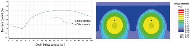
Figure 4 Moisture content on the day of the cut, after 12 h of irrigation, in loam soil with an emitter placement depth of 50 cm.
Table 3 Stress increase due to surface load of the tractor with front tire no. 4.
| Emitter placement depth (cm) | Surface stress (kPa) |
|---|---|
| 10 | 57.87 |
| 20 | 43.87 |
| 30 | 31.42 |
| 40 | 16.39 |
| 50 | 11.66 |
Since the greatest stress is near the surface, we used the stress at that depth (10 cm) to develop a Mohr's circle of failure and failure envelope for each soil type. Figure 5 indicates that a minimum cohesive strength of 14.70 kPa would be essential to avoid failure for the SCL soil. Similarly, the minimum cohesive strength for the CL and L soils would be 17.65 kPa and 15.69 kPa respectively (Figures 6 and 7).
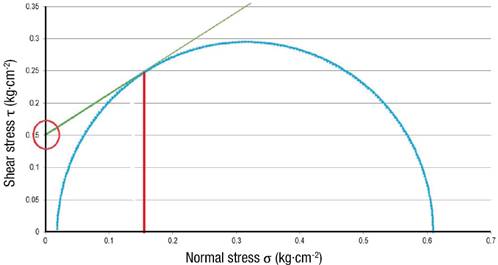
Figure 5 Mohr's circle and failure envelope for sandy clay loam soil at 10 cm depth with a tractor load at the surface.
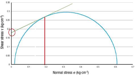
Figure 6 Mohr's circle and failure envelope for clay loam soil at 10 cm depth with a tractor load at the surface.
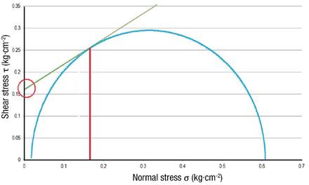
Figure 7 Mohr's circle and failure envelope for loam soil at 10 cm depth with a tractor load at the surface.
From Figure 1 it can be seen that a cohesive strength of 14.70 kPa occurs at a moisture content of about 26.8 % for the SCL soil, which is produced at 10 cm above the emitter (Figure 2). Hence, the minimum SDI system placement depth for this type of soil is 40 cm. Similarly, the cohesive strength of 17.65 kPa in CL soil is produced at a moisture content of 32.7 % (Figure 1), which occurs at 15 cm above the emitter (Figure 3), resulting in a minimum SDI system placement depth of 35 cm. For the L soil, the same analysis yields a minimum installation depth of 40 cm.
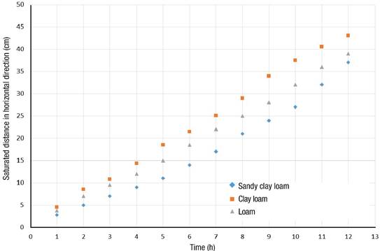
Finally, the greatest lateral extent of wetting after 12 h of irrigation on the day of the cut is shown for each soil in Figure 8. This represents one-half of the wetting pattern, so to attain adequate coverage, the horizontal spacing between driplines should be twice these values. Consequently, for the SCL spacing should be no more than 80 cm, for the CL no more than 90 cm, and for the L no more than 80 cm.
Conclusions
The analysis presented in this paper describes how the HYDRUS-2D model can be used in combination with soil shear strength and soil stress analysis methods to calculate a minimum depth of placement of SDI tape to avoid soil failure due to added loads on the soil surface such as the load added by a tractor during the harvesting process. This methodology was also used to determine maximum horizontal spacing using wetted patterns generated by the model.
Based on the analysis in this study, minimum depth placement for a drip emitter with a flow rate of 0.68 lph would be 40 cm, 35 cm and 40 cm for the SCL, CL and L soils respectively in order to avoid shear failure due to a tractor with a weight of 3 300 kg directly above the irrigation system. Maximum horizontal spacing for the soils was determined to be 80 cm for the SCL, 90 cm for the CL, and 80 cm L soils. These values can be rounded to 1 m, and they are the adequate spacing in order to supply the adequate amount of water to the root-zone, increase production and avoid striping presence in the plots.

