


Servicios Personalizados
Revista
Articulo
 Inglés (pdf)
 Artículo en XML
 Referencias del artículo
 Enviar artículo por email
Indicadores
-
 Citado por SciELO
 -
 Accesos
Links relacionados
-
 Similares en
SciELO
Similares en
SciELO
Compartir

 Permalink
Concreto y cemento. Investigación y desarrollo
versión impresa ISSN 2007-3011
Concr. cem. investig. desarro vol.5 no.2 Ciudad de México ene./jun. 2014
Convective heat transfer coefficients: experimental estimation and its impact on thermal building design for walls made of different mexican building materials
Jesús Chávez-Galán1, Rafael Almanza2 and Neftalí Rodríguez Cuevas2
1 Departamento de Ingeniería Eléctrica y Electrónica; Instituto Tecnológico de Puebla, Av. Tecnológico 420, Maravillas, 72220 Puebla, Puebla, México. E-mail: perspectiva2002@hotmail.com
2 Instituto de Ingeniería, Universidad Nacional Autónoma de México, Ciudad Universitaria, Coyoacán, 04510 México D.F., México. E-mail: ras@pumas.ii.unam.mx, nrodriguezc@iingen.unam.mx
Resumen
Algunos de los principales factores que determinan la fiabilidad del diseño térmico de un edificio son las propiedades térmicas y de transferencia de calor. Se llevaron a cabo algunas mediciones de propiedades de transferencia de calor para los materiales de construcción más comunes con el fin de ayudar a la optimización del proceso de diseño térmico de los edificios. Se presentan los datos experimentales sobre los coeficientes de transferencia de calor por convección para las paredes de diversos materiales de construcción en la posición vertical y horizontal utilizando una herramienta potente como es un túnel de viento.
Paredes de ladrillo rojo, tepetate (piedra caliza), adobe y concreto con tamaños de 0.46 x 0.56 x 0.06 m fueron fabricados, así como un prototipo de pruebas para montarlos y evaluar sus coeficientes de transferencia de calor por convección. Las mediciones se llevaron a cabo en el túnel de viento para un intervalo de 2 - 10 m / s de velocidad del viento. Los valores reportados oscilan entre 14 - 71 W/m2K según el material y la pared dependiendo de la posición, así como la velocidad del viento. El impacto del uso de los datos experimentales frente a los datos recomendados por las normas mexicanas en el diseño térmico de un edificio se evaluó a través de simulaciones con el software Energy -10; la estimación mostro una discrepancia en el consumo de energía para un edificio en cuatro lugares en México con diversas condiciones climáticas e irradiaciones solar global.
Palabras clave: convección, coeficientes de transferencia de calor, túnel de viento, irradiación solar global, materiales de construcción.
Abstract
Some of the main factors that determine the reliability of a building's thermal design are the thermal and heat transfer properties. Some measurements were carried out to help the optimization of the thermal design process of buildings. We present experimental data on convective heat transfer coefficients for walls of diverse building materials in vertical and horizontal position using a powerful tool as it is a wind tunnel.
Red brick, tepetate (limestone), adobe and concrete test walls of 0.46 x 0.56 x 0.06 m were manufactured, as well as a testing prototype to mount them and evaluate their convective heat transfer coefficients. Measurements were carried out at the wind-tunnel for a 2 - 10 m/s wind velocity interval. Reported values fluctuate between 14 - 71 W/m2K depending on material and wall position, as well as wind velocity. The impact of using experimental data versus data recommended by Mexican standards in the thermal design of a building was evaluated through simulations with the Energy - 10 software, estimating discrepancy of energy consumption for a building at four locations in Mexico with diverse climatic and global solar irradiation conditions.
Keywords: convection, heat transfer coefficients, wind tunnel, solar global irradiation, building materials.
Resumo
Alguns dos principais fatores que determinam a confiabilidade do projeto térmico de um edifício são as propriedades de transferência de calor e térmicas . Não há dados experimentais disponíveis na bibliografia internacional , relacionados com propriedades de transferência de calor por convecção para os materiais de construção mais utilizados, portanto, pela primeira vez, algumas medidas relacionadas com propriedades de transferência de calor por convecção para os materiais de construção mais utilizados foram realizadas para ajudar a otimização do processo de design térmico de edifícios. Apresentamos dados experimentais sobre os coeficientes de transferência de calor convectivo para paredes de diversos materiais de construção na posição vertical e horizontal usando uma ferramenta poderosa como é um túnel de vento.
Tijolo vermelho, tepetate (calcário), adobe e paredes de teste concretos de 0.46 x 0.56 x 0.06 m foram fabricados, bem como um protótipo de testes para montá-los e avaliar os seus coeficientes de transferência de calor por convecção. As medições foram realizadas no túnel de vento para o intervalo de um 2 - 10 m / s velocidade do vento. Os valores reportados oscilam entre 14 - 71 W/m2K dependendo do material da parede e de posição, bem como a velocidade do vento. O impacto do uso de dados experimentais contra dados recomendados pelos padrões mexicanos no projeto térmico de um edifício foi avaliada através de simulações com o software Energy - 10, estimando-se discrepância do consumo de energia para um edifício em quatro locais no México, com diversificada radiação solar climática e global condições.
Palavras-chave: convecção, coeficientes de transferência de calor, túnel de vento, a irradiação solar global, materiais de construção.
1. Introduction
Many international studies about convection heat transfer exist, which consider for example the convective coefficients for heated plates (Rebay et al., 2002) or roof mounted flat plate solar collectors (Sharples and Charlesworth, 1998). Studies about convection heat transfer in buildings are focused mainly on developing theoretical models (Sartori, 2006; Mirsadeghi et al, 2012), and a little on experimental measurements of convective heat transfer coefficients for some building elements like roofs (Clear et al., 2003), considering only geometrical and wind velocity aspects but not the kind of building material used. The main weakness of actual international bibliography is that studies are not focused on the kind of building material of which is done the building element, and also, just a small range of wind velocity (1-5 m/s) has been analyzed (Hagishima and Tanimoto, 2003). Modelling of natural convection in vertical and tilted photovoltaic applications was carried out by Lau et al, 2012. A method to calculate wind profile parameters of the wind tunnel boundary layer is described by Liua et al., 2003. Two different building envelope systems (2x4 stick-frame building: Structural Insulated Panel (SIP) building were constructed from a thick layer of polystyrene foam sandwiched between two fiber cement boards and the other one was a wood building model) under simulated environmental loads generated by the 12-fan Wall of Wind (WoW) at Florida International University (FIU). The low speed wind flow field was simulated using the 12-fan WoW at FIU. The simulation conducted in this study was targeted at a preselected eave height, with wind speeds of 6.7, 11.2, 15.6, 20.1 m/s to investigate the convective heat transfer under normal weather 9 conditions. The measurements were conducted on the roof and one of the side walls of the building models at different § wind speeds and three wind angles of attack. A plot has a mild positive slope, which indicates that the wind induced « convection heat loss increased as the wind speed increased by only a small amount over the roof surface and with AOA 0° (only -1 to -1.5 W/m2K), 45° (7 to 16 W/m2K) and 90° (-8 to -9 W/m2K) on side walls (Chowdhury and Suksawang, 2012). In Latin-American context, experimental studies about convection heat transfer properties of building materials have not been carried out, except for only a few exceptions consisting of qualitative analyses about thermal performance of walls with at real climatic and solar irradiation conditions (Corral et al., 2004).
The vast majority of buildings that are built in developing countries do not have adequate air conditioning equipment to maintain indoor air conditions within the ranges of human hygrothermal comfort. This means that the building itself, by design, orientation, materials and devices, must protect the occupants of moisture and thermal discomfort.
To improve the thermal design of buildings and achieve thermal comfort of the occupants with minimum power consumption; there is the official norm NOM-008-ENER-2001 [Ministry of Energy, 2001] in Mexico. Its main objective seeks to provide the items and information through which restricts the heat gain of a building through its envelope, in order to rationalize the use of energy in cooling systems. For heat gain calculation this standard proposes the use of a set of values for the thermal and heat transfer properties of the most common building materials such as concrete and red brick. Many of these values were obtained from international literature and have not been measured for the specific type of material and under climatic conditions prevailing in Mexico. An example is the convective heat transfer coefficient, for which only four default values are given regardless the type of building material or local wind conditions.
The usual wind speed in Mexican cities is between 0 to 6 m/s, but in coastal and others locations, wind speed can reach up to 9- 11 m/s at different levels of frequency (Ministry of Livestock and Hydraulic Resources, 1981).
For these reasons, measurements of convective heat transfer coefficients of diverse building materials were carried out for wind velocities of 2, 4, 6, 8 and 10 m/s. This paper presents the measurements of these heat transfer coefficients of horizontal and vertical walls made of red brick, tepetate (limestone), adobe and concrete.
1.1 Background
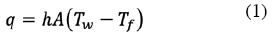
Newton's cooling law expresses the convection heat transfer for a hot plate:
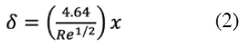
Convective heat transfer coefficients depend on many factors, including velocity, temperature and the kind of fluid. The hydrodynamic boundary layer thickness is (Holman, 1998)
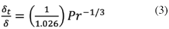
When a plate is warm over its entire length, the thermal and hydrodynamic boundary layer thicknesses are correlated by (Holman, 1998)
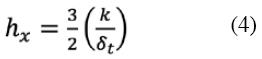
Considering a laminar flow regime, the local convective heat transfer coefficient for a hot plate is (Holman, 1998)
An evaluation of the heat transfer convection along a hot plate surface is only possible through the average convective heat transfer coefficient (Holman, 1998)
Also, local convective heat transfer coefficient for a hot plate with laminar parallel air flow is given by (Holman, 1998)
2. Experiment
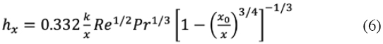
To measure the convective heat transfer coefficients of walls, we built a testing prototype consisting of a heater, an insulated box (cavity) and a base to mount the proof walls (Fig. 1).
The heater consisted of three 1500 W resistors connected in a parallel circuit and mounted on a steel structure. A 6 x 10⁻⁴ m thick copper plate of length 0.3 m and width 0.4 m was placed on the three resistors to improve the heat flow toward the proof wall. The box was made of 4 x 10⁻⁴ m thick aluminum walls thermally insulated by 0.02 and 0.05 m thick layers of ceramic fiber and expanded polystyrene (EPS), respectively. The base to mount the proof walls was made of steel bars. The box container had exterior dimensions of 0.6 x 0.7 x 0.2 m and internal dimensions of 0.46 x 0.56 x 0.15 m.
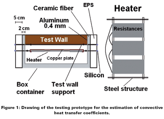
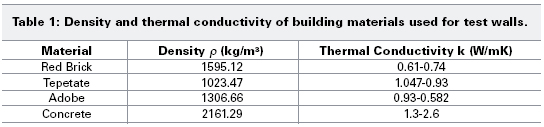
The test walls were built from red brick blocks, tepetate (limestone) and adobe, each of which were pasted with a mixture of cement, sand and lime. Also, a concrete wall with a compressive strength of 200 kg/cm2, similar to those used in ceilings, was built. The test wall dimensions were 0.46 x 0.56 m, and the thickness for the red brick, tepetate and concrete walls were 0.06 m, while the adobe wall thickness was the larger (0.08 m) because this material was the weakest. Fig. 2 shows a picture of a red brick wall mounted on the testing prototype.
Table 1 contains density and thermal conductivity of the building materials used for built the test walls. The density of building materials was experimentally estimated by water displacement method, whereas conductivity values were taken from Mexican and international bibliography (American Society of Heating, Refrigerating and Air Conditioning Engineers, 2001; Ministry of Energy, 2001).
The experimental measurements for the estimation of convective coefficients were carried out within the wind-tunnel of the Institute of Engineering-UNAM. The wind-tunnel is of the closed circuit type and has a rectangular test section of 1.70 x 1.13 x 0.77 m and a 75 hp engine. Temperature data were collected through a system of sensors manufactured with LM35AH semiconductors and connected to a data acquisition device, AT-MIO-16E-IO Multi I/O from National Instruments.
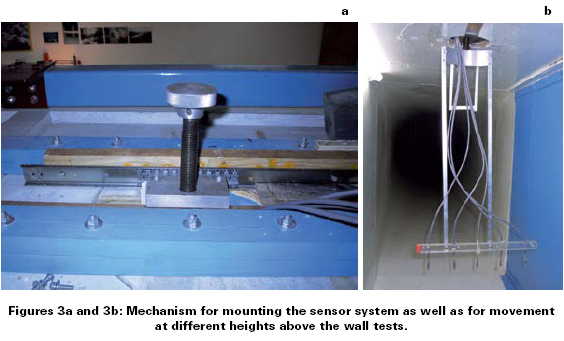
The vertical displacement of the sensors was achieved by means of a mechanism installed at the roof of the test section, basically consisting of an endless screw (Fig. 3-a) mounted on an aluminum base. Two vertical bearers of steel were coupled to the aluminum base to sustain the sensor system, which consisted of a pair of horizontal Lucite bars fastening five temperature sensors (Fig. 3-b).
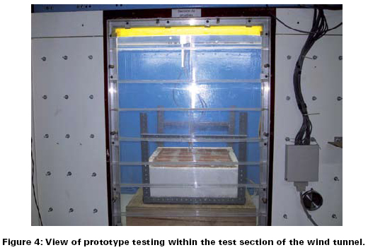
The testing prototype (and hence the test wall mounted on it) was installed horizontally and vertically inside the test section of the wind-tunnel such that the shorter length of the wall (0.46 m) was parallel to the air flow direction. Sensors were situated on the wall surface, 0.23 m stream-wise from the main edge. An exterior view of the wind-tunnel's test section is shown in Fig. 4, during a test with the prototype in horizontal position.
The heater was switched on for 60 minutes during a warming up process without any air flow, and then a stream of air (wind) parallel to the surface of the test wall was produced. Its speed was measured by a hot wire anemometer, EXTECH brand, model 407,123. Once the temperature readings stabilized (the transitional stage ranged from 330 to 1820 seconds depending on the material, wind speed and position of the wall), the sensor system was moved vertically in regular steps of 1.5 mm above the surface of the wall. To estimate the convective heat transfer coefficient, we applied Eq. (1), where the temperature values were the average of the sensor system readings.
3. Impact on the building's thermal design process
To estimate the impact of using experimental data in a building's thermal design process, a simulation was performed using the Energy-10 software (version 1.5).
The E-10 thermal simulation engine executes hourly thermal and daylight performance calculations based on hourly weather data for the site in question, the building description and the operating characteristics. The software provides 9 a detailed evaluation of solar gains through windows, heat flowing in and out of walls, thermal storage in all building § materials and heating, ventilation and air conditioning system (HVAC) performance. The simulation calculates the heat transfer from point to point within the building every 15 min throughout a simulated year. The thermal analysis is carried out using a thermal network mathematical modeling approach; the HVAC analysis is in steady state, and the daylight analysis uses a split flux method. For the thermal network representation of heat flow among building elements, p the energy is exactly balanced at each node of the network. Such a simulation is based largely on the central-difference of finite-difference equation solutions. HVAC is quasi-steady and is quite detailed, accounting for both sensible and latent energy transfers. Iteration is performed at each time step to ensure consistency between the thermal loads and systems simulations.
The house used for this simulation was a 70 m2 apartment with a concrete ceiling, a mosaic-ceramic floor and 16 cm-thick brick walls. The orientation was north to south, with four 3-mm thick single-pane soda-lime glass windows facing north and four facing south. The ratio of window to wall area was 20%. The simulation process compared the energy consumption for the building when Mexican standard recommended data were used against the energy consumption when the experimental data were used. The apartment in both cases was considered to be inhabited by 5 persons. The simulation also considered the use of heating by electrical resistances, as well as air-conditioning equipment with a direct expansion cycle and a COP of 2.6. The geographic locations used in this simulation were: Mexico city, Chihuahua city, located in the north-central part of Mexico, Mexicali city, located in the northwest of Mexico, and Merida city, located in the southeast of Mexico, all of them with very different weather conditions. Table 2 shows the annual average and extreme values of temperature, as well as the average relative humidity (Ministry of Livestock and Hydraulic Resources, 1981) and global horizontal solar irradiation (Almanza et al., 1992), for each locality. The interval of comfort temperature was taken as 22-25.5°C.
4. Results
4.1 Convective heat transfer coefficients
Temperature profiles were measured to determine the thickness of the thermal boundary layer. The results for a horizontally positioned red brick wall and a wind speed of 8 m/s are shown in Fig. 5, and they are in agreement with temperature profiles reported in other studies (Davies et al., 2005). As can be seen, the main air temperature change occurred over the first 4.5 mm.
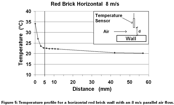
The same behavior was observed in all the walls for wind speeds of 6, 8 and 10 m/s. Employing Eq. (2) to calculate the hydrodynamic boundary layer thickness and considering that Pr = 0.708, we obtained a 0.0037 m thickness. If we used Eq. (3), the thermal boundary layer thickness was 0.0041 m, representing an 8.8% discrepancy compared to the 0.0045 m experimental result. This discrepancy is easily explainable by two factors, the roughness of the wall surface and the error in measurements of the vertical distance between the sensors system and wall surface.
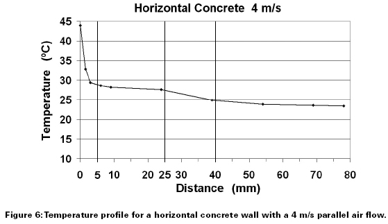
For low wind speeds (2 and 4 m/s), after the sensors were moved a distance beyond the boundary layer thickness as predicted by Eq. (3), the air temperature readings still showed a downward trend; thus we assumed that free flow temperature was not yet attained. Such behavior of the air temperature was more notorious with the horizontal concrete wall and a 2 m/s airflow because even at the highest possible vertical displacement of the sensors system (0.0078 mm), the sensor readings still showed a slight downward trend; therefore, we were not able to measuring the boundary layer thickness because of the design limitations of our system. Fig. 6 shows an example of this case for a horizontal concrete wall and a 4 m/s wind velocity. The free flow temperature is reached, but this measurement is shifted some millimeters beyond that predicted by Eq. (3).
Being that the parameter Gr/Re5/2 for horizontal walls and Gr/Re2 for vertical walls, ranged 2.2 x 10⁻⁴ - 3.9 x 10⁻⁵ and 3.6 x 10⁻² - 9.1 x 10⁻³ respectively, for low wind speed (2 and 4 m/s), we do not consider the mixed convection to explain the widening of thermal boundary layer, because these values for the parameters exclude the effects of natural p convection for a Pr = 0.708 (Martynenko and Khramtsov, 2005).
Such a behavior is explained by the humidity content of the test walls. For porous building materials like red brick or adobe, a great part of the water content was evaporated during the 60 minute warming process. For a concrete wall,the evaporation was more sluggish because of the wall's low porosity. Consequently, for "high" wind velocities the evaporated water was not yet detected by the top sensors, but for "low" velocities the air stream was not capable of dragging the evaporated water coming out from the test wall. This hypothesis is supported by the high thermal conductivity of the concrete compared with the other building materials and the correspondingly larger amount of heat coming out from the concrete wall towards the air. Therefore, the temperature of air near the wall surface rises quickly, the density and Reynolds number (Re) diminish, and the viscosity increases, causing an augmentation of the Prandtl number (Pr) and the thickness of the hydrodynamic and thermal boundary layers. This augmentation is supported by the low speed of the heat carriers (air particles) that results in an "overheating" of such heat carriers as they absorb more heat during their time of travel along the surface of the wall. Thus, Eq. (4) was not used as an alternative method to calculate the convective heat transfer coefficients of the test walls since the thicknesses of the thermal boundary layer estimated from the temperature profiles were distorted by the evaporated water coming out of the test wall.
From Fig. 6, in concordance with thermal boundary layer theory, the temperature curve diminishes suddenly in the 3 mm nearest to the wall surface; however, between 3 and 24 mm the curve is constant at a value above the free flow temperature. This disruption is due to the influence of water steam coming out of the test wall on the air temperature. For the 25 - 39 mm interval, the influence of the water steam decreases, as the temperature curve decreases slowly, until finally vanishing; at 40 mm, the temperature behavior is practically constant, i.e., free flow temperature is reached.
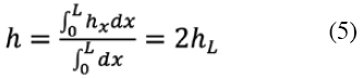
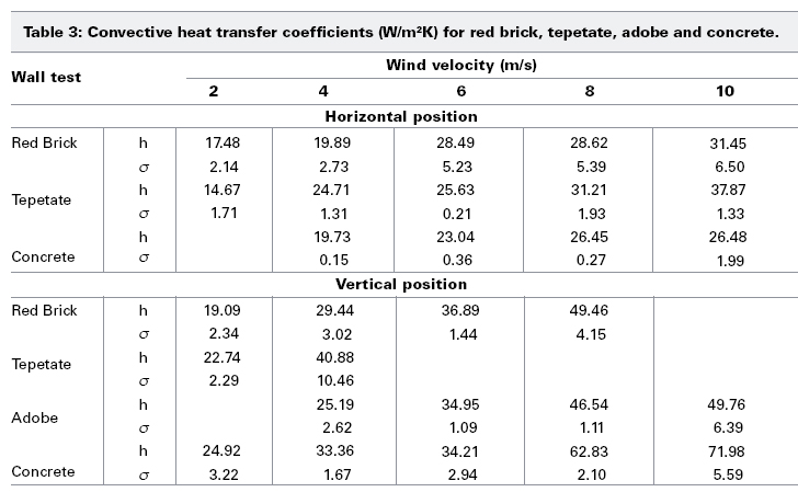
Table 3 summarizes the results for test walls of red brick, tepetate, adobe and concrete, in both horizontal and vertical position, always considering an air flow parallel to the surface of the wall. Heat losses from the box enclosing the electric resistances were estimated for each test, considering metallic areas exposed to the air flow (from the steel base for walls) and using the convection heat transfer model described by the Eq. (6). Thus, heat losses were considered for the calculation of convective heat transfer coefficients, and ranged between 8.2 - 18.4% for tests with horizontal walls, and 11.6 - 25.9 for tests with vertical walls. Five different tests were made in each case, so that in Table 3 the standard deviation o of the estimated values of the convective coefficient is also included.
If we compare the values in Table 3 with those proposed by the Mexican standards (Ministry of Energy, 2001), it is possible to see a substantial difference (200 - 400%). However, the values in Table 3 are similar to experimental data reported in some international studies for flat plates and a wind velocity interval of 1-5 m/s (Hagishima and Tanimoto, 2003; Sharples and Charlesworth, 1998). Sartori E. (2006) makes a comparison between several of the experimentally obtained equations currently used for convective heat transfer coefficients in flat surfaces and, based on the principles of boundary layer theory, suggests an equation that tries to reach a consensus between all the results. Using this equation, Sartori evaluates the convective coefficient for a wind velocity interval of 2 - 5 m/s, and the results range between 4 and 25 W/m2K, which is consistent with our data.
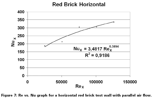
A graph of Nu vs. Re for a horizontal red brick test wall with parallel air flow is presented in Fig. 7. Table 4 contains the equations that relate the numbers Nu and Re obtained for each wall considered, as well as their respective correlation coefficient.
4.2 Energy-10 Simulation
Fig. 8 presents the simulation results for a building with red brick walls in Mexico City. This location experiences a mild climate throughout the year. A great energy consumption in such an apartment is because air conditioning (heating and cooling), and energy is also required for illumination of the building, defined by the term lights. Other sources of consumption include the energy required for heating water and running electrical devices.
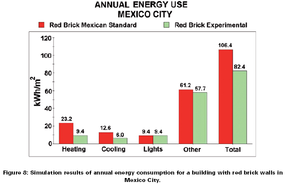
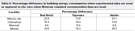
Results from the simulation reveal a decrease of 22.5% in the building energy consumption when experimental data are used as opposed to the case when Mexican standard recommended data are used. During the simulations only the values of thermal convective properties of building materials were modified to compare both cases (experimental and Mexican standard properties data), so the diminution on energy consumption of the building that resulted from simulations is due mainly to the used value for the thermal convective coefficient. Percentage differences were calculated for the other localities, too, and the results are shown in Table 4. The fact that the percentage differences are positive means that the building energy consumption when experimental data are used was less than for the case when Mexican standard recommended data are used. Therefore, we could have an error of 22.5% at least, during the process of thermal design of a building when inappropriate data is used. Depending on type of weather as well as solar irradiation conditions of the locality where building will be constructed, an inadequate choice of values for convective heat transfer coefficients can lead to greater error.
5. Conclusions
The main conclusion is that has been used successfully a wind tunnel to obtain heat transfer coefficients for different building materials. This establishes a methodology for other researchers could use it with other building materials fabricated in their countries.
Convective heat transfer coefficients for walls made of different building materials were experimentally measured in vertical and horizontal position. The obtained values are in agreement with theoretical and experimental data reported internationally for low wind speeds (1 - 5 m/s). However, some of the main contributions of this work are that generates new experimental data of convective heat transfer coefficients for walls; also, they were measured for a wider range of wind velocities (2 - 10 m/s), and considering a variety of building materials: red brick, adobe, limestone and concrete.
For the measurement of convective coefficients of building materials, it is important to consider the humidity content of the wall because it influences the air temperature readings near the wall surface and therefore distorts the measurement of the temperature profile. Therefore, a determination of the thermal boundary layer is not possible.
From the simulation results, we can deduce that for the cases examined, erroneous higher energy consumption is predicted when Mexican standard recommended data are used in the thermal design process of a building instead of our experimental data. This situation could generate an overdesign of air conditioning equipment and other mistakes that directly impact on energy consumption in buildings, with associated economic and environmental consequences.
Acknowledgment
The authors would like thank the financial support of Dirección General de Asuntos del Personal Académico from National University of Mexico (DGAPA-UNAM) through the project IN-109505. Julio Gonzalez and Ceferino Figueroa help during the measurements in the wind tunnel. Lauro Santiago make the system for acquisition data.
Nomenclature
A - Area of plate in contact with the fluid (m2)
Gr - Grashof number
Nu - Nusselt number
Re - Reynolds number
Tf - Fluid temperature (K)
Tw - Hot plate temperature (K)
h - Convective heat transference coefficient (W/m2K)
hx - Local convective heat transfer coefficient (W/m2K)
k - Thermal conductivity of air (W/mK)
q - Rapidity of heat transference (W)
x - Distance from the main edge (m)
δ - Hydrodynamic boundary layer thickness (m)
δt - Thermal boundary layer thicknesses (m)
References
Almanza, R., Estrada, V., Barrientos, J., 1992. "Actualization of the Mexican Republic's global solar irradiation maps", No. 543, Engineering Institute Series, UNAM, (in Spanish) México, pp. 37. [ Links ]
American Society of Heating, Refrigerating and Air Conditioning Engineers, 2001. Fundamentals Handbook, E.U.A. [ Links ]
Chowdhury A. G. and Suksawang N., 2013, "Development of Hurricane Resilient Composite Structural Insulated Wall Systems for Residential Buildings", August 1, 2012, Florida hurricane loss mitigation program 2012, Annual Report, January 2013. [ Links ]
Clear, R.D., Gartland, L. and Winkelmann, F.C., 2003. "An empirical correlation for the outside convective air-film coefficient for horizontal roofs", Energy and Buildings, 35, pp. 797-811. [ Links ]
Corral, M., Gallegos, R. and Luna, A., 2004. "Experimental study of construction systems for most typical walls in housing at warm climate regions", Proceedings of XXVIII National Week of Solar Energy, ANES, Oaxaca City, México. [ Links ]
Davies, M., Martin, C., Watson, M. and Ni Riain, C., (2005). "The development of an accurate tool to determine convective heat transfer coefficients in real buildings", Energy and Buildings, 37, pp. 141-145. [ Links ]
Hagishima, A. and Tanimoto, J., 2003. "Field measurements for estimating the convective heat transfer coefficient at building surfaces", Building and Enviroment, 38, pp. 873-881. [ Links ]
Holman, J.P., (1998). Heat Transfer, C.E.C.S.A., First Ed., México. [ Links ]
Lau G.E., Sanvicente E., Yeoh G.H., Timchenko V., Fossa M., Ménézo C., Giroux-Julien S, 2012. Modelling of natural convection in vertical and tilted photovoltaic applications, Energy and Buildings, 54 pp. 810-822. [ Links ]
Liua G, Xuanc J and Parka SU, 2003, A new method to calculate wind profile parameters of the wind tunnel boundary layer, Journal of Wind Engineering and Industrial Aerodynamics 91, pp. 1155-1162. [ Links ]
Martynenko Oleg G. and Khramtsov Pavel P., 2005. Free-Convective Heat Transfer, Springer, The Netherlands. [ Links ]
Ministry of Energy, 2001. Official Mexican Standard NOM-008-ENER-2001: Energetic Efficiency in buildings, shell of nonresidential buildings, Official Daily of the Federation, (in Spanish) México. [ Links ]
Ministry of Livestock and Hydraulic Resources, 1981. Mexican Climatologic Averages 1951-1980, (in Spanish) México. [ Links ]
Mirsadeghi, M., Cóstola D, Blocken B, Hensen J.L.M., 2013, "Review of external convective heat transfer coefficient models in building energy simulation programs: implementation and uncertainty", Applied Thermal Engineering 56, pp. 134-151. [ Links ]
Rebay, M., Lachi, M. and Padet, J. 2002. "Mesure de coefficients de convection par méthode impulsionnelle-influence de la perturbation de la couche limite", International Journal of Thermal Sciences, 41, pp. 1161-1175. [ Links ]
Sartori E., 2006. "Convection coefficient equation for forced air flow over flat surfaces", Solar Energy, 80 (9), pp. 1063-1071. [ Links ]
Sharples, S. and Charlesworth, P.S., 1998. "Full-scale measurements of wind-induced convective heat transfer from a roof-mounted flat plate solar collector", Solar Energy, 62 (2), pp. 69-77. [ Links ]

