


Services on Demand
Journal
Article
 text in
  English (pdf)
 Article in xml format
 Article references
 Send this article by e-mail
Indicators
-
 Cited by SciELO
 -
 Access statistics
Related links
-
 Similars in
SciELO
Similars in
SciELO
Share

 Permalink
Tecnología y ciencias del agua
On-line version ISSN 2007-2422
Tecnol. cienc. agua vol.9 n.4 Jiutepec Jul./Aug. 2018 Epub Nov 24, 2020
https://doi.org/10.24850/j-tyca-2018-04-05
Articles
Simulation and review of a small-scale device for wave energy conversion
1Universidad de Guanajuato, Departamento de Ingeniería Eléctrica, Salamanca, Guanajuato, México, ia.hernandez@ugto.x
2Universidad de Guanajuato, Departamento de Ingeniería Eléctrica, Salamanca, Guanajuato, México, x.gonzalez@ugto.mx
3Universidad de Guanajuato, Departamento de Ingeniería Eléctrica, Salamanca, Guanajuato, México, apizano@ugto.mx
4Universidad de Guanajuato, Departamento de Ingeniería Eléctrica, Salamanca, Guanajuato, México, jesusmp23@ugto.mx
5Universidad de Guanajuato, Departamento de Ingeniería Eléctrica, Salamanca, Guanajuato, México, gomezma@ugto.mx
The exploration and analysis of wave energy potential in some Mexican coastal nodes is complemented by this work, shich presents an electromagnetic analysis and simulation of the transducer device for converting wave energy into electricity. The device developed for this purpose is the permanent magnet linear electric generator (LEG). The wave energy potential obtained in a preliminary work at various points in Mexican coastal waters provides a precedent for the design of this device. The application of linear generators to obtain electrical energy from alternative sources of energy is a topic that is increasingly of interest for the progress of new distributed generation system. Therefore, in addition to determining the energy potential through electromagnetic simulation, this work also analyzes the performance and energy quality supplied by a linear generator. The simulation developed in this work is based on the displacement spectrum, and is a function of the significant wave height and its periodicity in the Mexican coastal points analyzed in the preliminary work. This study also contributes to both the design and development for micro-generation systems based on wave power, widening the range of electric power converters to assist in the energy control and quality of these linear generator devices.
Keywords Wave energy; wave energy conversion; linear generator; micro-grids; energy sustainability
En este trabajo de investigación se aborda la exploración y el análisis del potencial energético undimotriz en la costa mexicana a través del análisis y la simulación electromagnética del dispositivo transductor, para la conversión de energía del oleaje en electricidad; un dispositivo que se desarrolló para este propósito es el generador eléctrico lineal (GEL) de imanes permanentes. El potencial energético del oleaje, obtenido en un trabajo preliminar, en diversos puntos en aguas costeras mexicanas, proporciona un panorama precedente para el diseño de estos dispositivos. La utilización de generadores eléctricos lineales para conseguir energía eléctrica por fuentes alternas es una temática que cada vez toma mayor fuerza para el progreso de nuevos sistemas de generación distribuida (microrredes), por lo que este trabajo, además de determinar el potencial energético a través de la simulación electromagnética del dispositivo, analiza el rendimiento y calidad energética proporcionada por GEL. El análisis de simulación desarrollado en este trabajo se fundamenta con base en la obtención del espectro de desplazamiento, en función de la altura significativa de las olas y su periodicidad en los puntos costeros mexicanos analizados en el trabajo preliminar. Además, se contribuye al diseño y desarrollo de dispositivos enfocados a la microgeneración por undimotriz, lo que abre el abanico de posibilidades para el modelado y desarrollo de convertidores de electrónica de potencia, para ayudar al control y la calidad energética de estos dispositivos generadores eléctricos lineales.
Palabras clave conversión de energía por oleaje; energía undimotriz; generador eléctrico lineal; microrredes; sustentabilidad energética
Introduction
The Mexican electric power industry is currently undergoing some indispensable and necessary changes in the way it distributes energy. It also aims to harness its energy resources in a rational, sustainable, and efficient manner for social and economic benefits. The national goals are to provide energy to all communities in the country, with competitive prices and quality. Distributed generation (microgrids) is a viable option for the energy industry to implement. At present there are designs and developments of wind and photovoltaic generation, however Mexico is still lagging in research and devices that use new energy alternatives. Therefore, this paper focuses on the design, analysis, and research related to the performance of the linear electric generator, which is used in the conversion of wave energy into electrical energy. As an overview of the energy performance and quality provided by a LEG for harnessing wave energy, this will help with the design of a wave energy microgrid, in order to use its energy optimally and efficiently. With micro-generation, the opportunity is created to develop new energy conversion devices capable of using alternative and sustainable energies, such is the case of the LEG, developed and tested for ocean wave energy (Vining, Lipo, & Venkataramanan, 2011; Viola, Trapanese, & Franzitta, 2014). In addition, the LEG has been used in electric generation by means of internal combustion pistons (Wang & Howe, 2005; Wang, West, Howe, Zelaya-de-la-Parra, & Arshad, 2007) and for hybrid vehicles (Rinderknecht, & Herzog, 2010). The LEG design was reviewed by Danielsson, Eriksson and Leijon (Danielsson, Eriksson, & Leijon, 2006), where this device was described and having been developed in order to be coupled to a wave energy conversion system (WEC), using a buoy (Polinder, Damen, & Gardner, 2005) and a submerged air filling chamber, known as Archimedes Wave Swing (AWS). In Mexico, there are reports of the results from tests of a hydro-generator called Impulsa, for use with marine currents (López-González, Silva-Casarín, & Mendoza-Baldwin, 2011).
With the WEC system, the waves have uneven and irregular movements, which affect the voltage and power output of the LEG. With the objective of optimizing the output power (De-la-Villa-Jaen, García-Santana, & Montoya-Andrade, 2014) present a control method. With this background and with the exploration of the energy potential developed in the preliminary work, there is an interest in developing and investigating the energy performance and quality provided by an LEG when implemented by a WEC system in coastal points of Mexico. The study carried out by this work aims to identify the energy performance and quality provided by a WEC system through electromagnetic simulation and experimentation with a small-scale prototype. This provides a basis to establish efficient mathematical models for studies of power flows in micro-generation systems using the WEC system, and helps with the specification of electronic power components that guarantee the LEG’s energy stability and quality in a WEC system.
General design of the linear electric generator
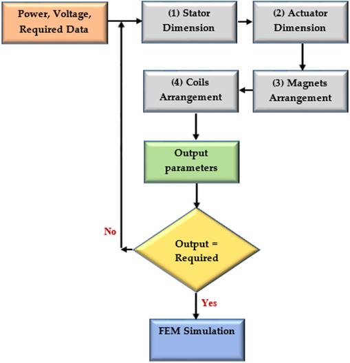
The linear electric generator used in this work has a tubular (cylindrical) design, defined in this way for its ease in the electromagnetic simulation ?both two-dimensional (2D) and three-dimensional (3D). In general, the designed LEG has four elements to be dimensioned in our design process: 1) stator, which hosts the induced magnetic flux; 2) actuator, a piece that captures the axial movement of the wave; 3) permanent magnets, which are parts that provide the magnetic power needed to induce voltage; 4) windings, which is where the electromotive force (or induced voltage) is induced. The windings considered for the LEG were simulated for both a single-phase and three-phase voltages, the latter making the LEG more compact than the single-phase type. The windings are formed with donut-type coils connected in series. The design process is iterative, as shown in the flow chart in Figure 1.
In the initial stage of the process, the input variables are introduced: power
desired, voltage generated, and the stroke and average speed with which the
magnets will move. For our work, the stroke depends on the significant height
(Hs) of the average wave, which was determined in the
coastal points analyzed in the preliminary work. The average speed depends of
the swell period (
where A
s
is the dimension of the stator surface, given in m2, and since
the device is tubular, A s is the surface of the cylinder given by
We proceed to calculate the actuator part, the piece in axial movement. Here, the diameter of the arrow and its necessary length are calculated according to the number of magnets required to be attached to it.
The determination of the dimensions of the actuator can be summarized by:
where A
a
(m2) is the cross-section of the arrow where the magnets will
be mounted, with which it is possible to obtain their diameter D
a
(m);
The required number of turns is then determined, as well as the dimensions of the windings based on the caliber of the conductor. The calculation of the coil is based on the number of turns of the stator, Ns, needed to generate the desired voltage, V gen (V). The calculation of the number of laps is determined by:
With the dimensioning of the four entities of the generator, it will be possible to estimate the losses, and with that calculate the machine efficiency percentage, % η, with:
where P losses (watts) represents the losses of the machine in the stator conductors due to the current and losses by currents induced in the stator and actuator. The force (N) for the generation is determined by:
P mec are the mechanical losses due to friction in the supports of the arrow. For simplicity in the design of the generator, these losses were considered negligible.
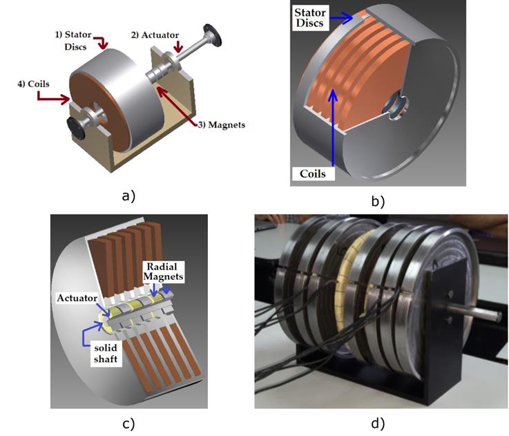
The comparison stage consists of checking the output variables of the voltage generated, the stroke, and the output power. If these do not comply with the input values, a new process is started by calculating a new stator, actuator, and coil dimensions until satisfying the values required by the input. When this is met, it is validated by means of electromagnetic simulation with the finite element method (FEM). A prototype with a small power of 100 W, 50V single-phase was developed, which allowed us to validate the design and expand the knowledge for the possible manufacture of a prototype with greater power. The geometric model of the LEG is shown in Figure 2, which shows: the elements it contains; the stator, formed by sweet iron discs with a relative permeability, μr, of approximately 4 000; the windings, manufactured with copper conductors. For the actuator, the same stator material was used (black iron), and the mounted magnets were neodymium.
Dynamics of the movement of the ocean waves used for generation
Ocean wave energy is a very attractive alternative energy for distributed generation in Mexican coasts. According to the preliminary work, the use of LEG seems to be the most convenient way to use this source of energy. The general scheme for wavelength micro-generation is shown in Figure 3, where it is possible to note two components: 1) the WEC unit, which contains a buoy element that is the translator of the wave energy and is coupled to the axis of the LEG; and 2) the power stability and control unit, which is used to store and attenuate power fluctuations at the LEG output. This unit contains the electronic power and control components needed to obtain stable power transmission to the network or local load. In the WEC system, the upward and downward movement of the wave is absorbed by the buoy, creating mechanical energy that will be converted into electricity by the LEG. Thus, the characteristic of the wave greatly influences the design of the LEG. In this work, the characteristic of the wave was obtained from the data provided by the preliminary work (González, Hernández, & Barrios, 2017).
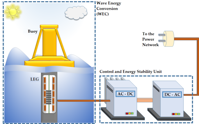
Figure 3 General scheme of the distributed generation system for the use of wave energy using a LEG.
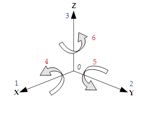
A floating asymmetric body, such as a buoy, can have different movements, or degrees of freedom (see Figure 4). There are six, and are described as follows (González et al., 2017): 1) translation on the x-axis (surge), which indicates the positive forward advance of the body; 2) translation on the y-axis (sway), which indicates lateral displacement, which is considered positive and to the left; 3) translation on the z-axis (heave), which indicates body height (positive upwards); 4) rotation on the x-axis (roll), indicating lateral body swing, positive is to sink the right side of the body; 5) rotation on the y-axis (pitch), indicating vertical pitch, positive is to sink the front part of the body; rotation on the z-axis (yaw), indicating the horizontal pitch of the body, positive is to turn left.
The dynamics of the movement of the movable part of the LEG can be determined by the equation that governs the movement of the WEC. For simplicity, a single degree of freedom in the buoy was considered. This means only vertical movement y(t) and ascending and descending. Therefore, by applying Newton's second law in this direction, the equation that governs the movement can be written as:
where f h represents the hydrostatic forces of the wave and f m represents all the mechanical forces of the system present in WEC, considering all the components of forces present in the system:
it is possible to summarize (6) as:
The equation of motion in the Laplace domain is:
where f
e
is the force of excitation of the wave (the profile of a regular wave is
a simple sinusoidal function for regular waves); m is the mass of the buoy plus
the mass of the actuator, A, of the LEG; B is the damping coefficient, which
depends on the buoy’s body and the wave frequency (a regular Mexican wave in
coastal areas has typical periods of 3 to 10 s) since the design of the LEG
involves considering movements of the actuator with low frequencies (less than
0.3 Hz); C is known as the load coefficient and is the energy conversion
capacity; K represents the spring constant;
The wave dynamics, f e (t), are considered for the simulation with a sinusoidal wave profile for a regular wave. In the case of an irregular wave, it is based on distortion models obtained from the spectrum proposed by Pierson and Moskowitz (Pierson & Moskowitz, 1964). In order to have a more realistic simulation with the data obtained for the significant height and periodicity of the wave in the different points of the Mexican coast, a distortion model was obtained that enables emulating the wave dynamics. This model is composed of the sum of Fourier terms:
where the values of A0 to A5 and B1 to
B5 denote the amplitude of the function. This means that the
effective value of the function will be at the desired significant height, Hs.
Table 1 summarizes the values used
for these constants (10). It also contains the parameter, w, that denotes the
average frequency of the wave, which is a function of the periodicity,
Table 1 Values for the simulation of the displacement of the designed LEG.
| Constants | ||
|---|---|---|
| Ai | Bi | |
| i = 0 | 0.0049 | --- |
| i = 1 | - 0.0161 | - 0.0156 |
| i = 2 | - 0.0206 | - 0.0400 |
| i = 3 | 0.0237 | - 0.1679 |
| i = 4 | - 0.0705 | - 0.0552 |
| i = 5 | 0.7530 | 0.5812 |
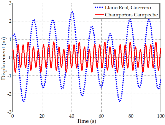
Most of the points analyzed in the coast of Mexico have a single model, given by (10), which characterizes them, since each point has its own waves and periodicity characteristics (see Table 2). In this work, (10) represents a model of the average displacement of the LEG’s actuator during a full day. Simulating a full day (86 400 s) in FEM is inconvenient due to the expense and computational time, and because model (10) is a continuous and repetitive series, with a random amplitude, so that the simulation of 10 min (600 s) could be considered as representative. For the simulation study developed in this work, the electromagnetic design of the LEG considered the node that resulted in the highest prediction of energy potential, which was the Guerrero node, Llano Real (Latitude 17 ° N, Longitude 110° 30' W).The node with the lowest potential value, corresponded to the Champoton node, Campeche (Latitude 19 ° 30 ' N, Longitude 91° 30' W). For each of the nodes analyzed, it was necessary to customize the design. So in this preliminary estimation and simulation stage, it would be inconvenient to design each of the generators. For this reason, only the node with the highest estimated power and the lowest node were considered. Table 3 presents the summary, with the values of Hs and Tz for these nodes. The profile of the movement obtained for the simulation of the displacement of the piston in the WEC system in these two nodes is shown in Figure 5. As can be seen, there are more waves in Champoton than in the Real Llano node, but with a lower significant height, which has an exceptional effect on the movement of the piston with magnets inside the LEG, affecting the extraction of power.
Table 2 Values obtained for significant height, Hs, and periodicity,
| Geographic information | Hs (m) Annual average |
|
||
|---|---|---|---|---|
| # | Zone | Nearest town | ||
| 1 | Nayarit | San Blas | 0.532 | 10.139 |
| 2 | San Francisco | 0.724 | 10.281 | |
| 3 | Colima | Peña Blanca | 1.119 | 10.282 |
| 4 | San Juan de Alima | 1.273 | 10.313 | |
| 5 | Guerrero | Barra de Potosí | 1.238 | 10.272 |
| 6 | Llano Real | 1.233 | 10.311 | |
| 7 | Copala | 1.160 | 10.271 | |
| 8 | Oaxaca | Santa María Chicometepec | 1.239 | 10.302 |
| 9 | San Mateo del Mar | 1.321 | 8.834 | |
| 10 | Aguachil | 1.235 | 9.578 | |
| 11 | Chiapas | Tonalá | 0.982 | 10.089 |
| 12 | Pijijiapan | 1.015 | 10.141 | |
| 13 | La Encrucijada | 1.166 | 10.134 | |
| 14 | Tapachula | 1.229 | 10.164 | |
| 15 | Campeche | Campeche | 0.498 | 2.959 |
| 16 | Champotón | 0.598 | 3.225 | |
| 17 | 0.419 | 2.741 | ||
| 18 | Carmen | 0.483 | 3.288 | |
| 19 | 0.696 | 3.644 | ||
| 20 | 0.723 | 3.568 | ||
| 21 | Veracruz | San Andrés Tuxtla | 0.724 | 4.234 |
| 22 | Lechuguillas | 0.797 | 4.43 | |
| 23 | Papantla | 0.803 | 4.464 | |
| 24 | Tuxpan | 0.917 | 4.445 | |
| 25 | Ensenada de Mangles | 0.905 | 4.501 | |
Table 3 . Values for significant wave height, periodicity, and estimated power for two nodes.
Simulations with FEM and evaluation of results
To extract the power from the LEG by means of electromagnetic simulation, LEG
designs were developed to be used in the WEC system with two nodes on the
Mexican coast. Table 3 contains the
average Hs and
A 5 kW LEG was designed for the Champoton node and a 100 kW for the Llano Real node, considering the possibility of having 10 units with the same capacity.
The simulation of the LEG with FEM was done in an asymmetric module because the device is tubular. Using this module saves time and computational memory. It also provides a 3D panorama of the magnetic flux density inside the device. The stroke or displacement of the piston with the magnets is a function of the significant height of the wave, and the time it takes the piston with magnets to travel a cycle is given by the periodicity of the wave.
Figure 6a shows the magnetic flux lines in a cross-section of the device. Figure 6b presents the 3D magnetic flux density inside the device. The voltage generation that is sought with this design is 240 V rms (or effective value). If the waves were regular, a sinusoidal voltage would be expected, but because the waves are irregular and are given by the proposed displacement spectrum (10), a distorted voltage (harmonics) is obtained (see Figure 7a).
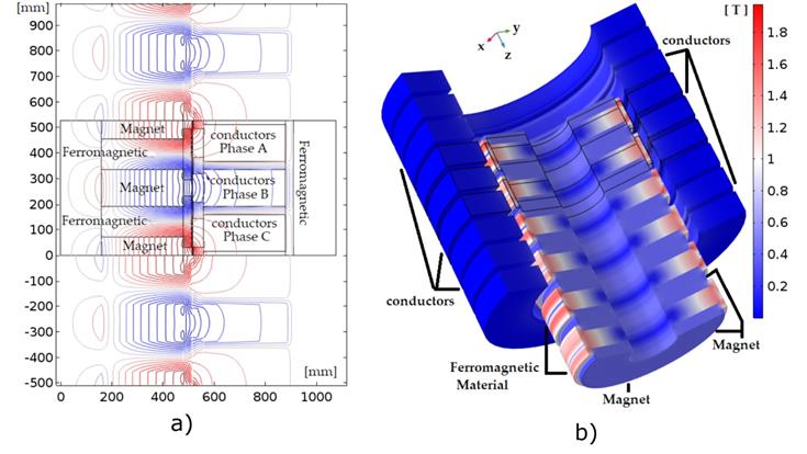
Figure 6 The electromagnetic simulation of the LEG: a) magnetic flux lines and b) magnetic flow density inside the LEG.
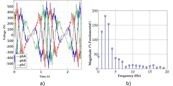
Figure 7 a) Voltage of 240 Vrms generated in the simulated LEG for the Champoton node; b) frequency spectrum generated to obtain the THD of the voltage signal.
Results of the energy quality delivered by the LEG
To analyze and evaluate the quality of energy supplied by the LEG, the voltage signal generated is used, with which the total harmonic distortion, THD, is calculated. This parameter measures the number of harmonics of the output signal, and is given by:
The THD was calculated using the Fast Fourier Transform (FFT) method, which determines the frequency spectrum of the harmonics of the signal analyzed (Figure 7b).
The THD of the voltage obtained for the Champoton node was 47.96%. This means that almost 48% of the estimated output power of the LEG will be wasted by unwanted frequencies (distortion), partly caused by the irregularity of the wave movement, and possibly because of the LEG design itself.
For the Real Flat node, the THD of the obtained voltage corresponded to
55.39%, which means an output power of only 44.61% of the expected power.
This may imply that at lower frequencies or higher periodicities (
Conclusions
With the future goal of developing a micro-generation system (distributed
generation) that uses alternative sources of energy, a small-scale prototype was
studied and simulated to identify the energy performance and quality provided by
a wave energy conversion system (WEC). In González et al. (2017), the nodes or locations of buoys with
oceanographic data were established, and with those, the average energy
potential was determined, as well as two important parameters (Hs and
Referencias
Danielsson, O., Eriksson M., & Leijon M. (2006). Study of a longitudinal flux permanent magnet linear generator for wave energy converters. International Journal of Energy Research, 30, 1130-1145. DOI: 10.1002/er.1209 [ Links ]
De-la-Villa-Jaen, A., García-Santana, A., & Montoya-Andrade, D. E. (2014). Maximizing output power of linear generators for wave energy conversion. International Transactions on Electrical Energy Systems, 24, 875-890. DOI: 10.1002/etep.1747 [ Links ]
Ekstrom, R., Ekergard, B., & Leijon, M. (2015). Electrical damping of linear generators for wave energy converters-A review. Elsevier Renewable and sustainable Energy Reviews, 42, 116-128. DOI: 10.1016/j.rser.2014.10.010. Recuperado de https://www.sciencedirect.com/science/article/pii/S1364032114008272 [ Links ]
González, X., Hernández, I., & Barrios, H. (2017). Potencial energético undimotriz en nodos costeros de México. Parte 1: estimación energética. Tecnología y Ciencias del Agua, 8(6), 5-22. DOI: 10.24850/j-tyca-2017-06-01 [ Links ]
López-González, J., Silva-Casarín, R., & Mendoza-Baldwin, E. G. (2011). Aprovechamiento de la energía de las corrientes con el hidrogenerador Impulsa. Tecnología y Ciencia del Agua, 2, 97-110. [ Links ]
Magnetika Saiffe. (2017). Imán de neodimio anillo. Recuperado de http://www.imanes.com.mx/jalisco/verProducto.php?mod=NR27MAGNA [ Links ]
Pierson, W. J., & Moskowitz, L. (1964). A proposed spectral form for fully developed wind seas based on the similarity theory of S.A. Kitaigorodskii. Journal of Geophysical Research, J. Wiley & Sons Journals, 69(24), 5181-5190. DOI: 10.1029/JZ069i024p05181 [ Links ]
Polinder, H., Damen, M. E. C., & Gardner, F. (2005). Design, modelling and test results of the AWS PM linear generator. European Transactions on Electrical Power, 15, 245-256. DOI: 10.1002/etep.56 [ Links ]
Rinderknecht, F., & Herzog, H. G. (2010). Calculation of a linear generator for hybrid vehicle concept. International Conference on Electrical Machines. ICEM 2010, 1-5. DOI: 10.1109/ICELMACH.2010.5607780 [ Links ]
Shi, H., Cao, F., Liu, Z., & Qu, N. (2016). Theoretical study on the power take-off estimation of heaving buoy wave energy converter. Elsevier Renewable Energy, 86, 441-448. Recuperado de http://dx.doi.org/10.1016/j.renene.2015.08.027 [ Links ]
Vining, J., Lipo, T. A., & Venkataramanan, G. (2011). Experimental evaluation of a doubly-fed linear generator for ocean wave energy applications. IEEE Energy Conversion Congress and Exposition (ECCE), 4115-4122. DOI: 10.1109/ECCE.2011.6064329 [ Links ]
Viola, A., Trapanese, M., & Franzitta, V. (2014). Design considerations of transverse flux generator to sea wave energy. IEEE Oceans Congress, 34(2), 1-4. DOI:10.1109/OCEANS-TAIPEI.2014.6964432 [ Links ]
Wang, J., & Howe, D. (2005). A Linear permanent magnet generator for a free-piston energy converter. IEEE Electric Machines and Drives, 1521-1528. DOI: 10.1109/IEMDC.2005.195922 [ Links ]
Wang, J., West, M., Howe, D., Zelaya-de-la-Parra, H., & Arshad, W. M. (2007). Design and experimental verification of a linear permanent magnet generator for a free-piston energy converter. IEEE Transactions on Energy Conversion, 22(2), 299-306. DOI: 10.1109/TEC.2006.875434 [ Links ]
Received: May 26, 2017; Accepted: January 23, 2018
 Este es un artículo publicado en acceso abierto bajo una licencia
Creative Commons
Este es un artículo publicado en acceso abierto bajo una licencia
Creative Commons
