


Services on Demand
Journal
Article
 text in
  English (pdf)
 Article in xml format
 Article references
 Send this article by e-mail
Indicators
-
 Cited by SciELO
 -
 Access statistics
Related links
-
 Similars in
SciELO
Similars in
SciELO
Share

 Permalink
Revista mexicana de ciencias agrícolas
Print version ISSN 2007-0934
Rev. Mex. Cienc. Agríc vol.9 spe 21 Texcoco Sep./Nov. 2018
https://doi.org/10.29312/remexca.v0i21.1526
Investigation notes
Calibration of sensors for the determination of power applied to vertical vibratory tillage
1Posgrado en Ciencias de la Ingeniería- Tecnológico Nacional de México/Instituto Tecnológico de Aguascalientes. (jguillens3@hotmail.com; drcarlossl@yahoo.com).
2Universidad Autónoma Agraria Antonio Narro. Buena Vista Saltillo, Coahuila, México. Tel: 0052 844 4 11 03 23. (camposmsg@hotmail.com).
3Operaciones del Centro de Tecnología Avanzada- CIATEQ. oscarm.gonzalezb@gmail.com.
A device was developed to evaluate the energy consumption in the vertical vibratory tillage of the induced type, to determine the energy consumption required to achieve the plowing of the soil. The equipment is made up of an octagonal extended ring transducer (OAE), a supporting structure, an oscillating mechanism, a floor rotating chisel and a hydraulic system for the drive. The present work considers, the calibration in laboratory of the sensors of the octagonal of extended ring that allows to measure the horizontal force and vertical force during the plowing of the ground, the sensor to measure the frequency of the vibratory rudder and the torque sensor that allows measuring the torque consumed by the oscillating mechanism for breaking the ground. The transducer calibration results (OAE) for the vertical force had a calibration constant of 75.00 N mV -1 with a linearity of 99.8%, for the horizontal force a constant of 47.74 N mV -1 with a linearity of 99.7% and for the torque transducer a constant of 0.4538 Nm mV -1 with a linearity of 98.8%, guaranteeing high reliability and precision of the measurements of forces and torque.
Keywords: agricultural machinery; energy consumption; octagonal transducer; vibratory subsoiler
Un dispositivo fue desarrollado para evaluar los consumos de energía en la labranza vertical vibratoria del tipo inducida, para determinar el consumo de energía requerido para lograr la roturación del suelo. El equipo está conformado por un transductor octagonal de anillo extendido (OAE), una estructura de soporte, un mecanismo oscilatorio, un cincel roturador de suelo y un sistema hidráulico para el accionamiento. El presente trabajo considera, la calibración en laboratorio de los sensores del octagonal de anillo extendido que permite medir la fuerza horizontal y fuerza vertical durante la roturación del suelo, el sensor para medir la frecuencia del timón vibratorio y el sensor de torque que permite medir el par que se consume por el mecanismo oscilatorio para la ruptura del suelo. Los resultados de calibración del transductor (OAE) para la fuerza vertical, se tuvo una constante de calibración de 75.00 N mV -1 con una linealidad de 99.8%, para la fuerza horizontal una constante de 47.74 N mV -1 con una linealidad de 99.7% y para el transductor de torque una constante de 0.4538 Nm mV -1 con una linealidad de 98.8%, garantizando alta confiabilidad y precisión de las mediciones de fuerzas y torque.
Palabras clave: consumo de energía; maquinaria agrícola; subsolador vibratorio; transductor octagonal
Introduction
The work focuses on the reduction of energy consumption in the use of agricultural implements of primary tillage, specifically in a vibratory multicultivator. The structure of the work, in the first place, explains what the vibratory multicultivator consists of and then the calibration of the sensors is presented.
For implementation purposes, a multicultivator developed in the department of design of new products of the Tecnomec Agricola Company has been used. It is called multicultivator, because it allows to perform: subsoiling, vertical fallowing, and debarking. According to Cadena et al. (2012) this multicultivator was evaluated by the Department of Agricultural Engineering of the Autonomous Agrarian University Antonio Narro (UAAAN, for its acronym in Spanish), with excellent results in aspects such as soil disturbance, size of aggregates, power demand and fuel consumption.
Campos et al. (2015a) and Campos et al. (2015b) modified the multi-cultivator by placing shallow rudders on the front and long rudders on the rear. In the rudders of the back part, fins of different sizes were used to increase the disturbed surface. Using the theory of critical depth in tillage equipment, the field tests carried out with this arrangement enabled them to demonstrate that energy consumption can be reduced.
On the other hand, Campos et al. (2015a) have carried out research work related to intelligent tillage, where geographical information systems and global location (GPS) were used to map the land that is required to prepare, based on this map, the soil is broken at a variable depth depending on of its hardness, resulting in the variation of energy consumption.
Shahgoli et al. (2009) and Shahgoli et al. (2010) have reported that, -22.5° was the optimum oscillation angle for the reduction of draft force and power savings. In their study on the optimization of oscillatory frequency in vibratory tillage, the rudders were oscillated with an amplitude of ± 69 mm and an angle of oscillation of 27° using a forward speed of 3 km/h. The oscillation frequency was varied from 1.9 to 8.8 Hz. There was an optimum frequency close to 3.3 Hz that minimized the total motor power required to operate the subsoiler. When compared with a rigid tillage equipment, an engine power reduction above 26% was estimated. Additionally, he performed a simulation to calculate the dynamic behavior of the oscillating tractor-subsoiler system focused on the vibrations of the operator's seat. Sahay et al. (2009) demonstrated the effect on the depth of work by inducing vibration in the agricultural implement.
They developed equipment with modified transmission inducing vibrations at frequencies between 9-13 Hz and between 15-35 Hz. Inducing vibration the working depth was 15.3 cm while using the same equipment without vibration was 7.4 cm.
Wu and Song (2010) designed a scarifier for meadows, which shows stable work and effective disturbance with a forward speed of 1 m/s and a vibration frequency of 10.0 Hz. On the other hand, Tong (2009) adopted a mechanism of deep scarification combining small vibratory fins which generate the vibration using alternative rudder movement by means of a crank connecting rod mechanism. Li et al. (2009) developed a deep vibratory scarifier, compared the tensile strength between the vibratory and non-vibratory modes to a depth of 30 cm, the deep vibratory scarification effectively reduces the tensile strength from 13% to 18%. Dong et al. (2010) used a mechanism for breaking soil in pasture by means of a forced vibration device, they demonstrated that there is an optimum angle between the rudder and the direction of plowing, for the reduction of the tensile strength.
Zhao (2010) invented a deep scarifier, which was compared with a common scarifier, the tensile strength, the energy consumption was significantly reduced and the quality of the deep disturbance was raised in a similar structure of soil and conditions job.
Zhou (2009) linearized the resistance to the plowing, and concluded by means of dynamic calculations and repetitive tests that the vibration effectively reduces the specific resistance of the soil and the resistance to plowing. Also, Lili et al. (2013) performed a dynamic and experimental analysis of a vibrating subsoiler, finding that the best working conditions of the tillage implement ISZ-160 are: forward speed of 0.2 m/s and the frequency of vibration of 10 Hz, the tractive resistance is low and the effect of soil clearing is good. In a certain depth position, increasing the speed increases the tractive resistance. When the tractor moves very fast forward, the tractive resistance is reduced with a small amplitude in the vibratory condition compared to the non-vibratory condition.
The scope of this project includes the calibration of the sensors of the extended ring octagonal, sensor to determine the frequency of the vibratory rudder and the torque sensor, in order to determine the power consumption in a vibratory rudder used in vertical tillage.
Materials and methods
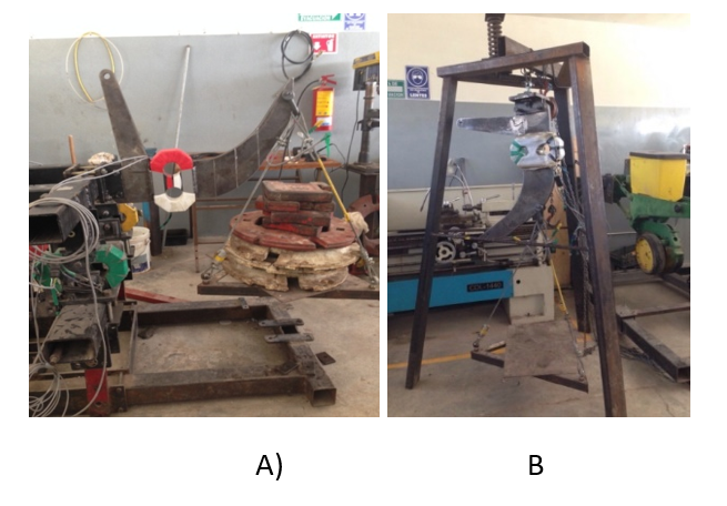
To determine the power used in primary tillage activities by applying induced vibration, we used a device whose rudders can vibrate at least 3.3 and 4.9 Hz, allows a vibration amplitude of 60 and 70 mm. This device consists of a structure or chassis, an oscillating rudder, a crank rod oscillating mechanism, a hydraulic motor, a flow regulating valve and a torque transducer. In the Figures 1 and 2 show the main components of the device used.
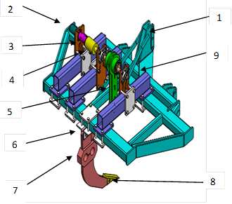
Figure 1 Isometric view of the vibratory tillage apparatus. 1) chassis; 2) hydraulic motor; 3) coupling; 4) torque transducer; 5) crank connecting rod; 6) rudder or chisel; 7) transducer oae; 8) peak; 9) adjustable rod support.
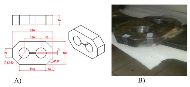
Figure 2 Extended ring octagonal transducer (OAE); A) Octagonal dimensions; B) location of strain gauges.
The experimental device is mounted to the three-point hitch system of a category II agricultural tractor and the oscillating system is driven by the tractor's hydraulic system. The chassis corresponds to the structure of the apparatus on which all the components are mounted, including the three-point hitch system. The crank mechanism is the one that causes the rudder to oscillate as shown in Figure 1, this mechanism is operated by means of a hydraulic motor of low revolutions and high torque, and the frequency of rotation is controlled by means of a valve flow regulator. Additionally, to measure the torque generated at the time of ground explosion, a torque transducer was placed between the coupling of the hydraulic motor and the oscillating mechanism.
To measure the horizontal and vertical force exerted by the ground on the rudder at the moment of the groundbreaking, an octagonal extended ring (OAE) transducer was manufactured with the dimensions shown in Figure 3. The OAE transducer was placed together at the rudder as shown in Figure 1.
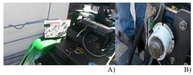
Figure 3 Sensor to determine the oscillation frequency of the vibratory rudder; A) electronic card; and b) sensor mounted on the arrow.
The OAE transducer has Kyowa brand strain gauges (type KFG-5-350-C1-11, Japan) for the determination of the force in the horizontal and vertical directions.
To determine the oscillation frequency in real time of the vibratory apparatus, an electronic card was developed using an infrared optoelectronic cutting sensor (model H21A1, USA).
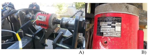
To measure the torque generated during the rupture of the soil, a torque transducer was used, facilitated by the INIFAP Experimental field Cotaxtla Veracruz, Mexico, by management of the Autonomous Agrarian University Antonio Narro (UAAAN) Saltillo, Coahuila, Mexico. The torque transducer serial number 52-E-73.792, was designed and manufactured by British Hovercraft Corporation Ltd., Osborne, East Cowes. I.W. Figures 4, 5 and 6.
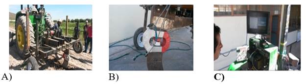
The laboratory research was carried out during the period from january to october 2015 in the Department of Agricultural Engineering, located 25° 21.52” north latitude and 101° 50” west longitude and an altitude of 1 740.5 meters above sea level, belonging to the UAAAN.
To measure the forces in the horizontal and vertical direction simultaneously, independently and with high precision, the OAE transducer was statically calibrated using eight weights of: 470.8, 470.8, 716.13, 716.13, 343.35, 343.35, 294.30, 294.30 N in accumulated form on the basket and in reverse the discharge, with 5 repetitions in each run. This process was done both for the direction of the horizontal force and for the vertical force.
The data acquisition system used in the calibration includes: Daqbook2000, a DBK43A model voltage conditioner, a Dell Optiplex GX520 computer and DaqView software.
In order to measure the Torque applied in the ground burst, the torque transducer was calibrated, for which the Logbook360 data acquisition system was used. The calibration was carried out with two lever arms of 0.65 and 0.85 meters and with 4 load weights of 294.30, 294.30, 343.5, 343.5 N accumulated and unloading in reverse, with 5 repetitions.
The data obtained were loaded into the Minitab V16 software and using linear regression, the curves and calibration constants were obtained.
Results and discussion
The results are presented in three sections that include the construction of the apparatus, calibration of the sensor to determine the frequency of the oscillatory rudder and the calibration of the extended ring octagonal transducer.
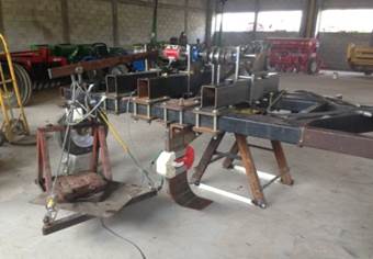
Construction of the apparatus
The vibratory tillage apparatus was manufactured at the Research and Applied Development Center of Aguascalientes SC, in collaboration with Tecnomec Agricola SA of CV, both located in Aguascalientes, Mexico.
In the Figure 7 shows the instrumented vibratory tillage apparatus, the OAE transducer that is used to measure the horizontal and vertical forces exerted by the soil on the chisel, the torque transducer used to measure the torque required for the burst of the ground, the infrared optoelectronic sensor to measure the frequency of the oscillating mechanism and the data acquisition system which captures all the information of the transducers in real time and stores them, to be later analyzed.
Calibration of the extended ring octagonal sensor
To obtain the same measurement accuracy in the two transducers, it was necessary to standardize the constant coefficient by means of the calibration adjustment in the 3 amplifier channels corresponding to each sensor and adjust the input gain, the compensator and the excitation voltage. In Tables 1 and 5 these values can be observed.
Table 1 Voltage values to calibrate the OAE transducer.
| Sensor | Cable | Channel | Excitation Voltage | Gain (V) | Scale (V) |
|---|---|---|---|---|---|
| Orthogonal | Black-blue | CH5 | 5.5 | 4.5 | 4.5 |
| Black-green | CH6 | 5.5 | 4.5 | 4.5 |
Table 2 Weight ratio against voltage means with 5 repetitions.
| Weight (N) | Average (mV) | Deviation standard | Coefficient of variation |
|---|---|---|---|
| 470.88 | 6.22 | 0.691 | 11.10 |
| 941.76 | 11.96 | 0.391 | 3.27 |
| 1 412.64 | 18.48 | 0.63 | 3.41 |
| 2 128.77 | 28.24 | 0.733 | 2.60 |
| 2 472.12 | 32.42 | 0.798 | 2.46 |
| 2 815.47 | 36.80 | 0.663 | 1.80 |
| 3 109.77 | 40.98 | 0.887 | 2.16 |
| 3 404.07 | 45.46 | 0.336 | 0.74 |
| 3 109.77 | 41.72 | 0.581 | 1.39 |
| 2 815.47 | 37.96 | 0.865 | 2.28 |
| 2 472.12 | 32.76 | 0.564 | 1.72 |
| 2 128.77 | 28.60 | 0.846 | 2.96 |
| 1 412.64 | 19.16 | 0.472 | 2.46 |
| 941.76 | 12.38 | 0.545 | 4.40 |
| 470.88 | 6.46 | 0.477 | 7.39 |
Table 3 Relationship of weights against averages of voltages and their 5 repetitions of calibration.
| Weight (N) | Average (mV) | Deviation standard | Coefficient of variation |
|---|---|---|---|
| 470.88 | 9.58 | 0.626 | 6.54 |
| 941.76 | 18.08 | 1.377 | 6.29 |
| 1 412.64 | 28.74 | 1.425 | 5.05 |
| 2 128.77 | 42.58 | 1.524 | 3.58 |
| 2 472.12 | 51.20 | 1.239 | 2.42 |
| 2 815.47 | 56.86 | 0.713 | 1.25 |
| 3 109.77 | 63.84 | 1.824 | 2.86 |
| 3 404.07 | 70.56 | 1.163 | 1.65 |
| 3 109.77 | 65.14 | 1.519 | 2.33 |
| 2 815.47 | 59.58 | 1.307 | 2.19 |
| 2 472.12 | 52.68 | 1.268 | 2.41 |
| 2 128.77 | 44.90 | 0.464 | 1.03 |
| 1 412.64 | 29.12 | 1.101 | 3.78 |
| 941.76 | 19.46 | 1.518 | 7.80 |
| 470.88 | 9.76 | 1.587 | 16.26 |
Table 4 Speed and frequency of oscillation of the chisel.
| Time (s) | Núm. of pulses | Frequency (Hz) | RPM |
|---|---|---|---|
| 10 | 147 | 2.94 | 176.4 |
| 10 | 148 | 2.96 | 177.6 |
| 10 | 149 | 2.98 | 178.8 |
| 10 | 148 | 2.96 | 177.6 |
| 10 | 149 | 2.98 | 178.8 |
Table 5 Voltage values to calibrate the torque transducer.
| Cable | Excitation voltage (V) | Gain (V) | Scale (V) |
|---|---|---|---|
| White-yellow | 2.5 | 2.5 | 2.5 |
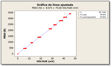
In Figure 8, the stepped graph of the calibration of the OAE transducer corresponding to the vertical force is presented. In the Table 2 shows the means of the values in mV of each step generated by each load to determine the calibration equation for the vertical force. Figure 9 shows the regression equation with the constant of 75.00 mV per N, with a linearity of 99.8%; very similar results were obtained by Campos et al. (2015c).
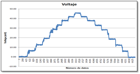
Figure 8 Loading and unloading cycles of the OAE transducer during calibration with different weights for vertical force.
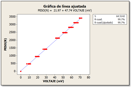
In Figure 10, the stepped graph of the calibration of the OAE transducer corresponding to the horizontal force is shown, in the Table 3 shows the means of the values in mV of each step generated by each load to determine the calibration equation for the force horizontal. Figure 11 shows the regression equation with the aforementioned constant of 47.74 mV with N a linearity of 99.7%, similar results obtained by Campos et al. (2015b).
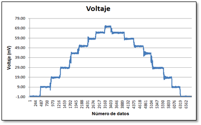
Figure 10 Loading and unloading cycles of the OAE transducer during calibration with different weights for the horizontal force.
Calibration of the sensor to determine the frequency of the vibratory rudder
To calculate the angular velocity with which the arrow transmits the vibration, it was necessary to install an encoder with five notches per revolution. The calibration consisted of sending a number of pulses and verifying that the LCD screen recorded the same number of pulses sent (Table 4). To avoid rebounds, a ceramic capacitor 104 was placed.
Calibration of the torque sensor
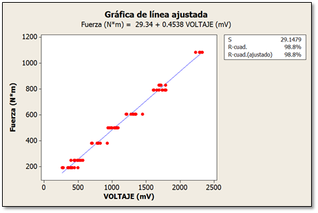
In Figure 12, the deformation in mV generated from the rise and fall of four weights can be observed with a lever arm of 0.85 m, in Table 6 the magnitude of the torque (Nm), which generated the deformation, is shown. The average value of the voltage (mV) counted with five repetitions of calibration. Figure 13 shows the regression equation with the constant of 0.4538 mV per Nm with a linearity of 98.8%.
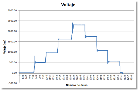
Figure 12 Load and discharge cycles of the torque transducer during calibration with different weights.
Table 6 Torque (Nm) vs. Voltage (mV) for the torque transducer.
| Moment (Nm) | Average (mV) | Deviation standard | Coefficient of variation |
|---|---|---|---|
| 191.3 | 367.0 | 53.7 | 14.64 |
| 250.2 | 524.1 | 33.8 | 6.45 |
| 382.6 | 764.1 | 56.8 | 7.43 |
| 500.3 | 1 037.1 | 55.8 | 5.38 |
| 605.8 | 1 081.0 | 412.0 | 38.11 |
| 792.2 | 1 723.8 | 72.2 | 4.19 |
| 828.9 | 1 719.8 | 37.8 | 2.20 |
| 1 084.0 | 2 290.0 | 39.4 | 1.72 |
| 792.2 | 1 685.1 | 54.9 | 3.26 |
| 605.8 | 1 292.8 | 98.1 | 7.58 |
| 500.3 | 1 009.5 | 48.5 | 4.80 |
| 382.6 | 782.6 | 93.1 | 11.89 |
| 250.2 | 459.3 | 42.7 | 9.29 |
| 191.3 | 371.4 | 102.2 | 27.51 |
Conclusions
According to the proposed objectives, it was possible to establish the calibration of the transducers of the vibratory multicultivator to determine the horizontal and vertical forces in real time that is exerted on the rudder during the work, in the same order of ideas the sensor used was calibrated. Measure the rudder oscillation frequency and finally calibrate the torque transducer. In the calibration of the transducers for vertical force we have a calibration constant of 75.00 N-mV -1 with a linearity of 99.8%, for the horizontal force a constant of 47.74 N-mV -1 with a linearity of 99.7% and for the torque transducer, a constant of 0.4538 N-mV -1 with a linearity of 98.8%, guaranteeing high reliability and accuracy of force, frequency and torque measurements in real time during field tests.
Literatura citada
Cadena, Z. M.; Campos, M. S. G.; López, S. A. y Zermeño, G. A. 2012. Configuración de herramientas de labranza vertical para reducir demanda de energía. Terra Latinoam. 30(1):279-288. [ Links ]
Campos, M. S. G.; Cadena, Z. M.; Ramírez, F. G.; Pacheco, L. J. L.; Reynolds, C. M. A. y Valenzuela, G. J. R. 2015. An experimental determination of specific soil resistance of a Sandy loam soil using vertical soil tillage in the northeast of Mexico. Agricultural Mechanization in Asia, Africa, and Latin America. 6(1):53-57. [ Links ]
Campos, M. S. G.; López, L. J. A.; Cadena, Z. M.; Reynolds, C. M.; Cuervo, P. N. y Ramírez, F. G. 2015b. Desarrollo de un penetrómetro integrado con tecnología GPS-RTK para la generación de mapas de resistencia a la penetración del suelo. Terra Latinoam . 33(2):119-128. [ Links ]
Campos, M. S. G.; Reynolds, C. M. A.; Cadena, Z. M.; López, L. J. A.; Cuervo, P. N. y Ramírez, F. G. 2015c. Desarrollo de un sistema integral de medición de fuerzas para la evaluación de implementos de labranza. Terra Latinoam . 33(2):139-149. [ Links ]
Dong, X.; Song, J.; Wang, J.; Li, Y. and Wu, G. 2010. Working mechanism of vibration spacing scarifier for grassland. Transaction of the CSAE. 26(10):119-123. [ Links ]
Gholamhossein, S.; Saunders, C.; Desbiolles, J. and Fielke, J. M. 2009. The effect of oscillation angle on the performance of oscillatory tillage. Soil Tillage Res. 104(1):97-105. [ Links ]
Gholamhossein, S.; Saunders, C.; Desbiolles, J. and Fielke, J. M. 2010. Optimising oscillation frequency in oscillatory tillage. Soil Tillage Res . 106(2):202-210. [ Links ]
Li, Y.; Liu, B.; Cui, T. and Zhang, D. 2009. Design and field experiment on 1SZ-460 lever-type subsoiler. Transactions of the Chinese Society for Agricultural Machinery. 40:37-40. [ Links ]
Sahay, C. S.; Thomas, E. V. and. Satpathy, K. K. 2009. Performance evaluation of a novel power tiller operated oscillatory tillage implement for dry land tillage. Biosy. Eng. 102(4):385-391. [ Links ]
Shahgoli, G.; Fielke, J.; Desbiolles, J. and Saunders, C. 2010. Optimising oscillation frequency in oscillatory tillage. Soil Tillage Res . 106(2):202-210. [ Links ]
Shahgoli, G.; Saunders, C.; Desbiolles, J. and Fielke, J. M. 2009. The effect of oscillation angle on the performance of oscillatory tillage. Soil Tillage Res . 104(1):97-105. [ Links ]
Tong, H. X. 2009. Development and application technology of vibratory subsioler. Farm Machinery Using & Maintenance. 5:25-26. [ Links ]
Wu, G. W. and Song, J. N. 2010. Design and experiment on vibration spacing scarifier for meadow. Transactions of the Chinese Society for Agricultural Machinery . 41(2):42-46. [ Links ]
Xin, L.; Liang, J. and Qiu, L. 2013. Dinamic analysis and experimental research of vibratory subsoiler system. J. Theoritical Appl. Inf. Technol. 48(2):1195-1201. [ Links ]
Zhao, D. W. 2010. Research and design of vibrating subsoiler. Agric. Sci. Technol. Equipment. 190(4):29-30. [ Links ]
Zhou, Y. 2009. Ploughing resistance and kinematics analysis of vibration fertilizer discharging mechanism. Modern Agric. Machinery. 10:74-76. [ Links ]
Received: March 2018; Accepted: June 2018
 Este es un artículo publicado en acceso abierto bajo una licencia Creative Commons
