


Servicios Personalizados
Revista
Articulo
 texto en
  Inglés (pdf)
 Artículo en XML
 Referencias del artículo
 Enviar artículo por email
Indicadores
-
 Citado por SciELO
 -
 Accesos
Links relacionados
-
 Similares en
SciELO
Similares en
SciELO
Compartir

 Permalink
Revista mexicana de ciencias agrícolas
versión impresa ISSN 2007-0934
Rev. Mex. Cienc. Agríc vol.9 spe 21 Texcoco sep./nov. 2018
https://doi.org/10.29312/remexca.v0i21.1536
Articles
Mechatronic system for the control of fertilizer and pesticide granules dispensers of a fertilizer seeder
1Posgrado en Ingeniería Agrícola y Uso Integral del Agua. Universidad Autónoma Chapingo. Km 38.5 Carretera México-Texcoco. C.P. 56230, Chapingo, Estado de México, México. Tel: 595 95 2 15 51.
The variable dosing machines make use of mechatronic systems for the drive and control of the dosers, replacing the traditional mechanical systems constituted by a drive wheel, transmission by chains and gears. Mechatronic systems allow a continuous and real-time change of the application dose. In this work a mechatronic system was developed for the control of fertilizer and granulated pesticide dispensers, which was adapted to a fertilizer seeder. The system is based on microcontrollers as a processing and control unit, as well as direct current motors with encoders to drive the dispensers. Changes in the application dose are achieved by controlling the rotation frequency of the dosing devices, using the pulse width modulation technique and the proportional-integral-derivative or proportional-integral control. The performance of the mechatronic system, to control the frequency of rotation of the fertilizer doser allows a lifting time of less than one second, maximum overshoot 14% and settling time of 1.5 to 2 s at frequencies ranging from 5 to 35 rev/min. In the case of the pesticide dispenser, the lifting time is less than one second, on maximum elongation less than 10% and settling time of 1.5 s for frequencies above 100 rev/min, at frequencies below this value variations of The control signal exceeds ±5%. Overall, the performance of the SM meets the requirements of variable dosing machines.
Keywords: microcontroller; PWM; PID control; fertilizer and agrochemical dosers
Las máquinas de dosificación variable hacen uso de sistemas mecatrónicos para el accionamiento y control de los dosificadores, reemplazando los sistemas mecánicos tradicionales constituidos por una rueda motriz, transmisión por cadenas y engranes. Los sistemas mecatrónicos permiten un cambio continuo y en tiempo real de la dosis de aplicación. En este trabajo se desarrolló un sistema mecatrónico para el control de los dosificadores de fertilizante y pesticida granulado, el cual fue adaptado a una sembradora-fertilizadora. El sistema está basado en microcontroladores como unidad de procesamiento y control, además de motores de corriente directa con codificadores para accionar a los dosificadores. Los cambios de la dosis de aplicación se logran con el control de la frecuencia de rotación de los dosificadores, utilizando la técnica de modulación por ancho de pulso y el control proporcional-integral-derivativo o proporcional-integral. El desempeño del sistema mecatrónico, para controlar la frecuencia de rotación del dosificador de fertilizante permite un tiempo de levantamiento menor a un segundo, sobreelongación máxima de 14% y tiempo de asentamiento de 1.5 a 2 segundos en frecuencias que van de 5 a 35 rev/min. En el caso del dosificador de pesticida, el tiempo de levantamiento es menor a un segundo, sobre elongación máxima menor al 10%, y tiempo de asentamiento de 1.5 segundos para frecuencias superiores a 100 rev/min, en frecuencias menores a este valor las variaciones de la señal de control rebasan el ±5%. De manera global, el desempeño del SM cumple con los requerimientos de las máquinas de dosificación variable
Palabras clave: control PID; dosificadores de fertilizante y agroquímico microcontrolador; PWM
Introduction
Precision agriculture (AP) is defined as the "management of spatial and temporal variability at inter-parcel level to improve the economic return and reduce the environmental impact" (Fountas et al., 2003). Its application allows to optimize the use of the resources, to diminish the negative environmental impact, to increase the profitability of the crops and to facilitate the achievement of the sustainability of the agricultural activity. The AP makes use of technologies such as global positioning systems (GPS), devices for detecting and storing information relating to interparceral variability, geographic information systems, models for decision-making, technologies capable of automatically controlling the agricultural equipment (mechatronics) in such a way that the regulation conditions of the same can be modified continuously and in real time (IDEA, 2010). One of the areas of greatest interest in the AP is the application of inputs at a variable rate, a promising concept that is not incorporated quickly enough into the productive practices of modern agriculture (Robert, 2002; Reyes et al., 2011).
The equipment used in the application at variable rate of fertilizer and pesticide online, make use of hydraulic or electromechanical systems for its operation. The first of them uses the hydraulic system of the tractor and the main actuators are hydraulic motors for the drive of the dosers. The second uses the electrical system of the tractor as the power source and the main actuators are direct current motors (DC) for driving the dosing devices (Bragachini et al., 2010). The latter has greater advantages, due to its lower cost and maintenance, besides being faster to reach the desired application dose. Mechatronic systems can be divided into the following key areas: 1) modeling of physical systems; 2) sensors and actuators; 3) systems and signals; 4) computers and logical systems; and 5) software and data acquisition (Bishop, 2002; Bolton, 2006).
The change of the dose of application of the inputs, is achieved by varying the angular speed or frequency of rotation of the dosers. One of the most used techniques to modify this variable, when the dosers are driven by direct current motors, is the pulse width modulation (PWM) (Wenbin et al., 2012; Atul et al., 2012; Sartori et al., 2015). To control its magnitude, open-loop control techniques are used, using stepper motors (Yang et al., 2015; Jianbo et al., 2104) or in closed loop, using servomotors or DC motors, with techniques of classical control PI or PID (Basilio and Mateos, 2002; Saranya and Pamela, 2012; Pratap, 2014).
In Mexico, the application of AP is scarce or null at both the research and productive levels, despite the benefits it allows to achieve; therefore, the objective of this research was the development (design, construction and testing) of a mechatronic system (SM) for the control of the dosage of fertilizer and pesticide continuously and in real time, adaptable to a fertilizer-seeder.
Materials and methods
Description of the fertilizer seeder
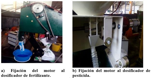
The fertilizer seeder used in this research was designed to work under conservation tillage conditions, it is marketed with one or up to eight bodies, each body has a pneumatic seed dosage system, a fertilizer dispenser and solid pesticides. It uses a toothed cutter disc, which functions as a driving wheel, transmission by chains and gears to drive the dosers, in the case of the fertilizer doser the transmission by chains and gears move to a pinion and this in turn to the crown, on which is fixed a bar located inside the hopper (Figure 2). Considering the operating speed of the machines for the application of inputs, with maximum speed of 12 km h, at this speed and with the settings of the machine selected for this investigation, the cutter disk would rotate at a maximum rotation frequency of 146 rev/min, the bar-disk dosing of fertilizer at 35 rev/min, and the grooved roller for dosing pesticide at 144 rev/min, these data were considered as design specifications and to perform the mechatronic system tests.
Mechanical subsystem
The SM was adapted to a body of the fertilizer seeder. To operate the granulated pesticide dispenser, the EMG49 gearmotor, with 24 volts of direct current (VCD), was used, with a rotation speed in vacuum of 160 rev/min, maximum torque of 1.6 Nm and power of 34.7 W. With an encoder integrated 245 pulses per turn of the arrow on each output line A and B. The arrow of the motor is coupled directly to the pesticide dispenser (Figure 1b).
To actuate the dispenser fertilizer one gearmotor 350W was used to 24VDC, with two output arrows, one from the reducer and the other direct from the motor. The arrow with reduction reaches a frequency of rotation in empty of 500 rev/min, and the arrow without reduction of 6 255 rev/min; in the latter, the set encoder was YUMO E6B2-CWZ3E to 1024 pulses per revolution in each output line A and B, which is fed between 5 to 15 VDC. The exit arrow with reduction drives a pinion-crown gear, by means of a chain transmission between the arrow of the pinion and the arrow of the gearmotor, in the crown the bar-disc that gives movement to the fertilizer is fixed (Figure 1a and Figure 2).
Electronic subsystem
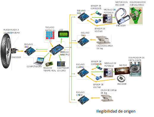
The SM is based on the ‘open source’ Arduino development platform for free hardware and software. It uses the Arduino MEGA board (Atmel Corporation, 2016a) as the main control unit, based on the Atmel2560 microcontroller. The following elements were connected to this board: liquid crystal display (LCD 20 x 4), real time clock, SD memory, matrix keyboard and three Arduino UNO boards (Atmel Corporation, 2016b) in I2C communication (Inter-Integrated Circuit), where the Arduino Mega board acts as a master and the Arduino Uno as slaves. To perform the laboratory tests, two more arduino were connected to measure the mass of the test material delivered by the dosers (Figure 2).
An Arduino-Uno was used to control the fertilizer doser and another for the pesticide doser. In each one the following elements were connected: voltage sensor, current sensor, incremental encoder, power unit and the Arduino Mega. Another Arduino Uno was used to measure the forward speed of the planter, to which a YUMO E6B2-CWZ3E encoder and the Arduino Mega were connected. A power unit was designed based on opto-couplers and power transistors, which amplify the PWM control signal sent by the microcontrollers to the motors isolating them from the high voltages. The SM is powered by the tractor's electrical system at a voltage of 24 VDC.
Control subsystem
The process followed for the development of the dosing control system was as follows:
Step 1. Experimentally we identified the equation that relates the pulse width (duty cycle) of the PWM signal to the pulse frequency of the encoder, this separately for each doser. For this, different step inputs of the pulse width were applied (taking the minimum value of 50 and the values to increase by 50 until the maximum value of 1023 was taken) and the pulse frequency obtained from the motor encoder was measured, with each selected pulse width the motor-doser was operated in a time of 10 seconds, taking measurements of the pulse frequency every 98.304 ms. The value of the frequency considered as a response to the applied pulse width of the PWM signal was the average of the measurements obtained from 2 to 10 s. In the case of the fertilizer doser, the test was performed with the motor coupled to the doser with the hopper empty. In the agrochemical doser was carried out under three conditions, the first only with the engine, the second with the engine coupled to the pesticide dispenser with the hopper empty and the third as in the previous case, but with the hopper full of test material and gate completely open.
Step 2. Characterization of the response of the system to a step input. It was obtained as the average behavior in 30 repetitions, of the application of a step input of the PWM signal (with a value of 1023) and its response in pulser frequency of the encoder, in the time interval of the beginning of the application of the input step (zero time) at 1.5 s and making measurements of the pulse frequency at regular intervals of 16.384 ms. The conditions under which the tests were conducted for the fertilizer and agrochemical doser were those described in step 1.
Step 3. Generation of the transfer function of the plant. Using the data obtained in step 2, the transfer function of the plant was determined using the ‘System Identification Tool’ tool of the System Identification Toolbox of the Matlab programming environment, calling this tool from the command window with the ‘ident’ instruction.
Step 4. Tuning the PID controller. With the transfer function of the plant, the tool ‘pid
tuner’ of the Control System Toolbox of Matlab was used, making a call to
this tool in the command window with the instruction ‘pidtool’, to find the
values of the constants
Where:
In Equation 3 it shows the expression that allows to determine the control signal, by reducing the difference between the reference (frequency of required pulses) and the measured value (measured pulse frequency) of the control variable in the system.
Where:
Step 5. Finally, the control algorithms of the mechatronic system were programmed. The
control algorithm programmed in the arduino one that controls the fertilizer
and pesticide dispenser is the one presented in Figure 3, where
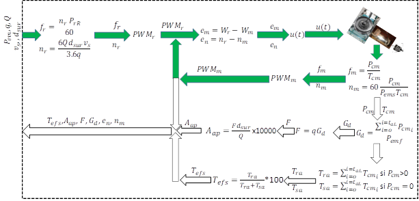
Nomenclature used: n_int = number of interruptions from the beginning of the sowing work until the present moment (dimensionless), G_d = turns given by the seed disk, t_aL = time counted since the beginning of the work (s),
Figure 3 Dosing control algorithm.
Programming and operation of SM
The SM programming was done in C++ language with the Arduino software version 1.0.5 [22].
The arduino uno (slave one) was programmed to determine the forward speed of the planter (
The arduino Mega governs the functioning of the SM. Controlling the mode of operation of the slaves in three modes, which are: inactivity mode, input application mode and test-calibration mode. When the SM is switched on, it starts in idle mode, waiting for the user to change the operating mode; either to the application or test-calibration mode. When one of these modes is selected, it activates the corresponding slaves to execute the selected operating mode and sends the data required by each slave for its operation. When the input application mode is active, the arduino mega expects the signal from the slave one that indicates that the speed of displacement of the planter has been updated, at which time it updates each one of the operation data of the slaves and extracts from them via I2C the data that characterize the performance of the dosers, in addition to checking and updating the operation data entered by the user or changing the operation mode.
When the SM operates in test-calibration mode, the user enters the rotation frequency to which the dispensers must turn and the number of turns they must make. Once active, the mega Arduino controls the rotation frequency of the dosers with the selected magnitude and stops them when they have made the turns chosen by the user, receiving the data of importance of each slave every 163.84 ms via I2C communication.
The arduino uno (slave two) was programmed to control the operation of the fertilizer doser and arduino uno (slave four) of the pesticide dispenser (Figure 2). Its operation starts with the configuration and initialization of each of the devices connected to it and waits for the master to assign the operating mode, either in application, test-calibration or inactivity mode; for each operating mode it receives from the master the data required to execute it and implements the dosing control algorithm (Figure 3). When the application mode is active, it expects the master to update the operation data and send the most important data of the application task, which is done every 163.84 ms. In the case in which the active mode of operation is that of calibration tests, it waits to receive updated operational data from the master and returns the most important data resulting from the activity, this is done until the condition of unemployment is met.
The algorithm implemented in the slaves that control the dosers is presented in Figure 3, which starts with the input
data sent by the master, which are: the advance speed of the planter (
Where:
Where: PWM is the required or measured pulse width of the PWM (dimensionless) signal and f the required or measured pulse frequency, both in the motor that drives the pesticide dispenser.
The difference between the required pulse width (
Where:
Once the programming and the control algorithm were implemented in each of the Arduino, tests were performed to determine the PID control performance using different values of the constants, based on the estimates with the Matlab PID Tuner tool. For each of the constants
Evaluation of the mechatronic system through laboratory tests
The tests were made using a body of a fertilizer-seeder, in the test bench of seeders of the laboratory of the National Center for Standardization of Agricultural Machinery (CENEMA), which belongs to the National Institute of Agricultural and Livestock Forestry Research (INIFAP). The test material used was commercial urea fertilizer (46-0-0), for the fertilizer and pesticide dispenser, based on the Mexican standard NMX-O-222-SCFI-2004 (Secretaría de Economía, 2004) and avoid the handling of toxic products in the case of the pesticide dispenser. The average properties of the test material were as follows: bulk density of 766.8 kg m3, coefficient of static friction of 30°, grain size less than 5 mm and humidity 0.22%.
In the test of each batcher. Five rotation frequencies were used for the fertilizer dispenser (dosing bar) 5, 12, 20, 27 and 35 rev/min; and five for the pesticide dispenser (grooved roller) 10, 32, 55, 77 and 100 rev/min. The opening of the gate that regulates the exit of the material from the hopper was placed in the middle position (50%) and the hopper was placed at a filling level of 80% of its capacity with the test material in both cases. At each rotation frequency four repetitions were made and for each repetition the dosing bar was rotated 20 times and the grooved roller 30 times. In each repetition the frequency of rotation of the dispenser, the control error, the number of turns, voltage and current of feeding of the motor were measured at regular intervals of 114.688 ms, in addition, the amount of test material delivered by each batcher was measured at regular intervals of 645 ms for the agrochemical batcher and 715 ms for the fertilizer.
The voltage and current sensor were verified with a digital multimeter (Model: UD87 from the company URREA Herramientas Profesionales, SA of CV), showing differences in measurements of less than ± 2% in both cases. The load cell was verified with calibrated weights of one, two, three, four and five kilograms obtaining a difference in measurement less than ± 0.05%.
Results and discussion
The adaptation of the mechatronic system consisted mainly in the fixation of the motors to the body of the planter to operate the dispensers and the electronic and control system allowed a joint operation of each one of the components that integrate the SM.
When applying different step inputs of the pulse width of the PWM signal to the system (motor-metering mechanism with empty hopper), a behavior was obtained in the rotation frequency for the fertilizer doser, which is shown in Figure 4a and for the dispenser of pesticide in Figure 4b. In the case of the fertilizer doser, a linear behavior is presented, while for the pesticide dispenser the behavior is non-linear.
a) PWM signal vs frequency of rotation of the fertilizer dispenser.
b) PWM signal vs rotation frequency of the pesticide dispenser.
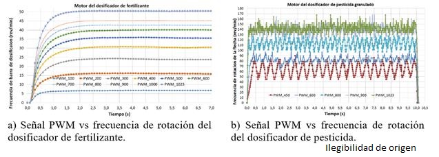
The fertilizer doser motor allows to obtain a higher precision and better adjustment when controlling the frequency of rotation, compared to the pesticide dosing motor, this due to the linear behavior since the pulse width (duty cycle) of the PWM signal it allowed to overcome the strength of resistance to movement in the doser was 25, being able to use the values in the range of 25 to 1023 to modify the frequency of rotation of the dispenser (Figure 4a). However, in the case of the pesticide dispenser, the pulse width of the PWM signal that allowed to overcome the resistance to movement was 450 and in the range of 850 to 1 023 there was almost no variation in the rotation frequency, achieving use only the values in the range of 450 to 850 (Figure 4b).
The transfer functions identified to account for the behavior of the plant for the fertilizer and agrochemical doser are presented in Table 1. The estimates of the constants
Table 1 Equations of the transfer function of the plant, of the controllers and values obtained from the constants of the controller for each of the dosers.
| System | Transfer function | Selected values of the PID constants | |
|---|---|---|---|
| Plant | Controller | ||
| EM49 |
|
|
Error>10% Kp= 0.329, Ki= 12, Kd= 0.05 5-10% of error Kp= 0.9, Ki= 4, Kd= 0.01 Error <5% Kp= 0.9, Ki= 4, Kd= 0 |
| MDPTV |
|
|
|
| MDPTL |
|
|
|
| MDFTV |
|
|
Error>10% Kp= 0.709, Ki= 6.778, Kd=0.01 5-10% of error Kp= 0.26, Ki= 1.32, Kd=0.01 Error <5% Kp= 0.26, Ki= 1.32, Kd= 0 |
EM49= motoreductor; MDPTV= pesticidal motor-doser with empty hopper; MDPTL= pesticidal motor-doser with full hopper; MDFTV= fertilizer motor-doser with empty hopper.
When determining the irregularity of delivery between repetitions of the dosers, according to Mexican standard NMX-O-222-SCFI-2004, it was found that the fertilizer dispenser has a maximum superior irregularity of 15% while for the pesticide dispenser it was lower to 3%. This indicates a high delivery irregularity of the fertilizer dispenser when using the same rotation frequency.
The average results of the repetitions in the fertilizer doser test are shown in Table 2, where an error in the programmed angular displacement with respect to the measurement of -0.84% at its maximum value was obtained, this in 20 turns of the doser. This implies that the effect due to the displacement error of the dispenser (theoretical angular displacement with respect to the real at different programmed rotation frequencies) in the variation of the quantity of fertilizer delivered (application dose) is low, which allows to assert that the mass of material delivered at each turn of the dispenser is affected by the change in the magnitude of the rotation frequency of the dispenser. This behavior is undesirable, since when adjusting a machine for the application of fertilizer, it is not expected that the application rate will change with the modification of the speed of advance of the machine for machines are drive wheel and mechanical transmission system.
Table 2 Results of the fertilizer and pesticide dispenser test.
| Fertilizer dispenser | Pesticide dispenser | |||||||
|---|---|---|---|---|---|---|---|---|
| FRP | FRM | E | ME | FRP | FRM | E | ME | |
| 5 | 5.04 | -0.84 | 93.35 | 10 | 9.51 | 4.92 | 2.88 | |
| 12 | 12.01 | -0.10 | 106.30 | 32 | 31.58 | 1.31 | 2.91 | |
| 20 | 19.92 | 0.37 | 142.04 | 55 | 54.85 | 0.28 | 2.86 | |
| 27 | 26.96 | 0.14 | 153.87 | 77 | 76.72 | 0.36 | 2.90 | |
| 35 | 34.96 | 0.11 | 169.93 | 100 | 99.67 | 0.33 | 3.00 | |
*Programmed rotation frequency (FRP), rev/min; measured rotation frequency (FRM), rev/min; error (E); % y Mass delivered by turning the dispenser (ME) g.
In Table 2, the results of the average amount of test material thrown by each turn of the pesticide dispenser are shown, in addition to the average error of the angular displacement repetitions in 30 turns, where it obtained a maximum of 4.92% at 10 rev/min.
The performance of the PID controller to regulate the frequency of rotation of the doser, in the case of the fertilizer doser: allows a lifting time of less than one second, maximum overshoot 14% and settling time between 1.5 to 2 s for frequencies that go from 5 to 35 rev/min (Figure 5a), in the case of the pesticide dispenser, allows a lifting time of less than one second, in this case the overshoot is not well defined but one could say that it reaches it in less than 1.5 s, the steady state with an error of the control variable of ± 5% only reaches it for the rotation frequency of 100 rev/min of the grooved roller and for the case of the rotation frequencies of 10 to 77 rev/min it exceeds (Figure 5b).
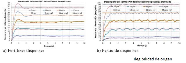
Tola et al. (2008) obtained for a variable dosing system, when using a granulated fertilizer dispenser, a fluted dosing roller driven by a 12VDC motor, errors of the target dosage in the range of ± 5% and a response time of the control system to adjust the application dosage in the range of 0.95 - 1.90 s.
Considering the error of angular displacement which is directly related to the dose of application of the dosers (fertilizer and pesticide) obtained in this investigation, it is inferred, that they are within the value ± 5% of the error of the dose of objective application and that the response time of the dosers to make the changes in the application dose are very similar to those reported.
Santori et al. (2015) found that, for a helical feeder driven by a 12VDC motor, at low rotation frequencies of the doser the error in the target fertilization dose was increased as the rotation frequency was decreased, obtaining an 8.3% error at 4 rev/min, from 5.5% to 12 rev/min and 3.5 to 20 rev/min and <1.5% at 24 rev/min, this behavior was also observed mainly in the pesticide dispenser, in the error of the rotation frequency control and the angular displacement.
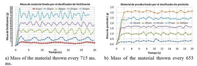
Because there is no reference in the determination of the behavior of the delivery of the input by the dosers, at small time intervals such as those that were measured in this investigation (in time intervals of 0.753 for the fertilizer dispenser and 0.653 s for the pesticide dispenser), since in all the cases consulted they make the determination of the cumulative application dose. Therefore, the analysis is only based on the standard deviation and the coefficient of variation. The results for the fertilizer dispenser are shown in Table 3 and Figure 6a, where it is observed that the delivery is irregular (non-uniform), based on the high values obtained from the coefficient of variation and for the case of the pesticide dispenser, according to the results obtained in Table 3 and Figure 6b, the delivery of test material by the dispenser is more uniform as the value of the rotation frequency of the dispenser increases, with the best results of 55 to 100 rev/min. This result contrasts with the error of control of the rotation frequency and angular displacement, compared with the fertilizer doser.
Table 3 Behavior of the delivery of the fertilizer and pesticide dispenser per second.
| Fertilizer dispenser | Pesticide dispenser | |||||||||
|---|---|---|---|---|---|---|---|---|---|---|
| Test rotation frequency (rev/min) | 5 | 12 | 20 | 27 | 35 | 10 | 32 | 55 | 77 | 100 |
| Average (g/s) | 8.61 | 21.25 | 47.60 | 48.96 | 99.47 | 0.45 | 1.51 | 2.53 | 3.69 | 4.69 |
| Standard deviation | 1.46 | 4.11 | 6.54 | 5.57 | 8.74 | 0.064 | 0.15 | 0.08 | 0.11 | 0.11 |
| Coefficient of variation (%) | 16.93 | 19.33 | 13.78 | 11.37 | 12.28 | 14.06 | 9.65 | 3.12 | 3.07 | 2.38 |
Conclusions
The performance of the controller of the fertilizer dispenser and the agrochemical doser is adequate to make changes in the dose of application continuously and in real time with a stabilization time of the rotation frequency between 1.5 and 2 s, with an error of angular displacement of the doser less than ± 0.84% for the fertilizer dispenser and with a maximum time of 1.5 s to reach the application dose, with an error in the angular displacement less than ± 1.5%, irregularity of delivery less than 5% for rotation frequencies from 10 to 140 rev/min in the case of the pesticide dispenser.
In general, the SM developed, meets the requirements for its application in the machine.
Literatura citada
Alfaro, R. V. M. 2003. Métodos de sintonización de controladores PID que operan como servomecanismos. Revista Ingeniería, San José, Costa Rica. 13(1-2):13-29. [ Links ]
Alfaro, R. V. M. 2002. Métodos de sintonización de controladores PID que operan como reguladores. Revista Ingeniería, San José, Costa Rica. 12(1-2):21-36. [ Links ]
Anaya, P. M. E.; Benítez, B. V. H.; Pacheco, R. J. H. y Montaño, V. F. 2014. Diseño de controladores P, PI y PID para el comportamiento dinámico de un servo-sistema hidráulico, basado en desarrollo experimental. UNISON-EPISTEMUS 16:13-21. [ Links ]
Atmel Corporation. 2016a. ATMEGA328/P Datasheet, 8-bit AVR microcontroller. San José, California, USA. http://www.atmel.com/Images/Atmel-42735-8-bit-AVR-Microcontroller-ATmega328-328P_datasheet.pdf. [ Links ]
Atmel Corporation. 2016b. ATmega640/V-1280/V-1281/V-2560/V-2561/V Datasheet, 8-bit AVR microcontroller. San José, California, USA. http://www.atmel.com/Images/Atmel-2549-8-bit-AVR-Microcontroller-ATmega640-1280-1281-2560-2561_datasheet.pdf. [ Links ]
Atul, K. D.; Nibbedita, C.; Sashi S. and Vinod, Y. 2012. PWM Based Automatic Closed Loop Speed Control of DC Motor. Inter. J. Eng. Trends Technol. 3(2):110-112. [ Links ]
Basilio, J. C. and Matos, S. R. 2002. Design of PI and PID controllers with transient performance specification. IEEE Transactions on Education. 45(4): 364-370. [ Links ]
Bishop, H. R. 2010. The mechatronics hand book. The Instrumentation, Systems, and Automation Society (ISA). The University of Texas at Austin Austin, Texas, USA. 18-25 pp. [ Links ]
Bolton, W. 2006. Mechatronics: electrical control systems in mechanical and electrical engineering. 3nd Ed. Addison-Wesley Longman, Harlow, England. 1 pp. [ Links ]
Bragachini, M.; Méndez, A.; Scaramuzza, F; Vélez, J. P. y Villarroel, D. 2010. Manejo de cultivos por ambiente. Evolución de la dosificación variable en Argentina. Proyecto Agricultura de Precisión INTA. Manfredi, Pcia. de Córdoba, Argentina. [ Links ]
Fountas, S.; Søren, M. P. and Simon, B. 2003. ICT in precision agriculture - diffusion of technology. Institute of Agricultural Sciences. The Royal Veterinary and Agricultural University, Denmark. [ Links ]
Instituto para la Diversificación y Ahorro de la Energía (IDEA). 2010. Ahorro y eficiencia energética en la agricultura de precisión. Madrid, España. 12-17 pp. [ Links ]
Jianbo, Z.; Junfang, X.; Yong, Z.; and Shun, Z. 2014. Design and experimental study of the control system for precision seed-metering device. Inter. J. Agric. Biol. Eng. 7 (3):13-18. [ Links ]
Arduino.Página web de Arduino. https://www.arduino.cc/. [ Links ]
Pratap, V.; Neelam, P.; and Chandrakant, K. 2014. Real time DC motor speed control using PID controller in LabVIEW. Inter. J. Adv. Res. Electrical, Electronics and Instrumentation Engineering. 3(9):12162-12167. [ Links ]
Reyes, A. J. F.; Berrios, A. D. F.; Ortega, B. R. A.; Wilson, D. E. y Flores, J. F. 2011. Calibración estática de un sistema de control automático de tasa variable de fertilizante. Santiago, Chillán, Chile. Agrociencias 46:51-62. [ Links ]
Saranya, M. and Pamela, D. 2012. A real time IMC tuned PID controller for DC motor. Inter. J. Recent Technol. Eng. 1(1):2277-3878. [ Links ]
Sartori, M. J. R.; Di Raimo C. ; Costa, C. R. R.; Montezuma, M. A. and Capello de Souza E. A. 2015. Study of an electromechanical system for solid fertilizer variable rate planting. Afr. J. Agric. 11(3):159-165. [ Links ]
Secretaría de Economía. 2004. Tractores, implementos agrícolas - sembradora neumática de precisión - especificaciones y método de prueba NMX-O-222-SCFI-2004, México. [ Links ]
Tola, E.; Kataoka, T; Burce, M; Okamoto, H and Hata S. 2008. Granular fertiliser application rate control system with integrated output volume measurement. Bio. Eng. 101(4):411-416. [ Links ]
Wenbin, Y.; Dada W.; Pengfei, J.; and Weiguo, L. 2012. The PWM speed regulation of DC motor basedon intelligent control. Systems Engineering Procedia. 3:259-267. [ Links ]
Yang, Li; Xiantao, He; Cui, Tao; Dongxing, Z.; Song, S.; Rui, Z.; Mantao, W. 2015. Development of mechatronic driving system for seed meters equipped on conventional precision corn planter. Inter. J. Agric. Biol. Eng. 8(4):1-9. [ Links ]
Received: April 2018; Accepted: July 2018
 Este es un artículo publicado en acceso abierto bajo una licencia Creative Commons
