


 nueva página del texto (beta)
 Inglés (pdf)
 Artículo en XML
 Referencias del artículo
 Enviar artículo por email
 Citado por SciELO
  Similares en
SciELO
Similares en
SciELO 
 Permalink

Introduction
The relationship among the spectral harmonics of an electric current induction motor, and its mechanical and electromagnetic problems is well known. Dorrel et al 1 studied how the magnitude of electric harmonics relates to the mechanical harmonics in motors focusing on eccentricity.
Riley et al 2 analyzed these relations to establish limits for the electric harmonics as they correlate with vibrations, concluding that there is a monotone relationship between both variables. Riley et al 3 finds, based on theoretical as well as on experimental bases, that there is a linear relationship between specific electric harmonics and mechanical vibration. Additionally, Riley et al 4 presents an analysis including the effect of externally induced vibrations. Finley et al 5 makes a complete analysis of the relation among electric harmonics and mechanical problems including misalignment, unbalance, bearings failure, fractured rotor bars, etc. Kral et al 6 proposes a technique to estimate unbalance using harmonics that are present in the electric power, showing positive results in assessing static and dynamic unbalance. Neelam 7 presents an analysis of the electric current as the most popular for failure diagnosis, not only electrical but also mechanical as well, showing effectiveness to determine abnormal operation of induction motors, including situations involving gear trains. Bellini 8 presents a paper review of the previous ten years showing a list of references and research activity classified in four topics: a) electrical failures, b) mechanical failures, c) signal processing for monitoring and analysis, and d) technical decision using artificial intelligence. Camargo 9 presents results of single-plane rotor balancing using electric harmonics that relate to mechanical unbalance.
Duque-Pérez, et al 10 deal with the analysis of condition monitoring in challenging situations characterized by high noise level in the current spectrum. They use additive models to separate the effects of different factors on the amplitude of the fault signatures. For diagnosis purposes, software ANOVA allows the subtraction of the contribution of a variable in the fault signature value, avoiding a bias produced by this variable.
García-Reynoso et al 11 develops an algorithm that uses magnitudes of harmonic components of electric current to determine the influence coefficients and the balance masses of a directly coupled rotor. The procedure requires three trial weights to carry on balancing. García-Reynoso et al 12 presents a new method for calculating the phase based on measurements of the relative phase of the harmonics present in the spectrum.
Instrumentation
The measurement system has the following elements: Hall-effect probes for electric current, signal conditioning, data acquisition system, and virtual instrument developer in G language. These elements are described below.
General information of these elements was discussed by García-Reynoso et al 11.
The virtual instrument is developed in Labview® 8.6, and it has user-friendly displays allowing reading and saving of desired information. Figures 1 and 2 show some of the displays.


Figure 1 shows the frequency spectrum with a harmonic component that is related to rotor imbalance as is obtained from the filtering process, as established by Riley 2. In this case, the 4-pole induction motor runs at 60Hz.
Figure 2 shows the three harmonic components in a polar diagram. It has been reported the phase relation among high order harmonics near 90Hz which tend toz ero with some variations that depends on the degree of rotor unbalance.
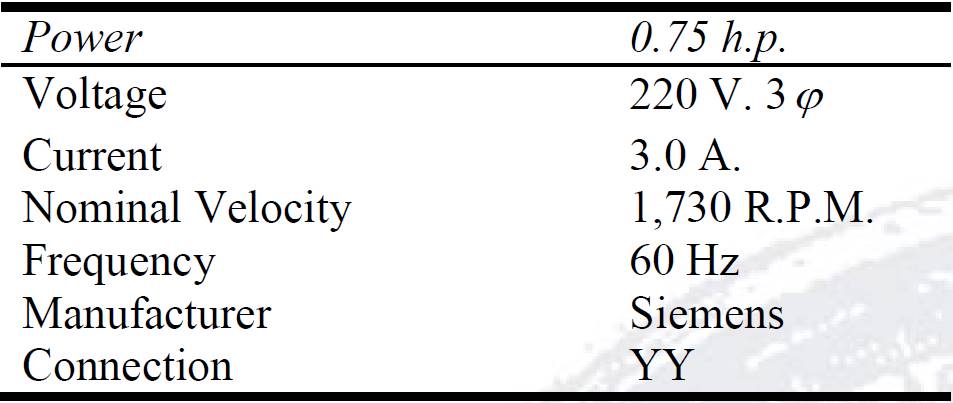
The experimental work conducted to validate this proposed method was based on an electric motor described in Table 1.
Measurements of residual- current signals
A residual current is considered as the remaining harmonics after subtracting the fundamental current circulating in a motor wiring. These harmonics are due to different effects, mechanical and electrical, as has been reported for some time 5, 8.
These currents are produced by a deformation of the magnetic field in the motor air-gap, as a result of mechanical unbalance. However, the residual condition is also obtained by motor eccentricity, asymmetry of coil structure of stator and rotor, that is, owing to static and dynamic irregularities in the air-gap 2, 5, 8.
By means of the sensing system, the fundamental current consumed by the motor, and the harmonics produced by the mechanical and the electromagnetic problems are obtained. The Fourier spectrum of the signal is displayed and the mechanical unbalance is indirectly determined by filtering the associated harmonics.
The measurement consists of a virtual instrument, a set of solid-state magnetic sensors and its signal conditioning. It is designed for 220 volts and a maximum of 15 amperes. Voltage is monitored through a set of transformers connected in star configuration with magnetic cores that respond to a maximum of 10 kHz. The electric signal is obtained using Hall-effect probes model M15 which have a range of 10 kHz.
Depending on harmonic order, there is an associated mechanical or electromagnetic problem. Of particular interest is the harmonic signal related to mechanical unbalance. These harmonics depend on the rotor slip, input frequency, and they occur at the frequencies given by the following expressions:
 (1)
(1)
 (2)
(2)
Adjusting harmonics to remove offset
It may be observed, for harmonics of a balanced-rotor condition that the relative phase angles among them (L 1 , L 2 , L 3 ) have values of 120° (low frequency). However, when unbalance ispresent these relative phase angles change due to the vector sum of the offset and the unbalance effect.
Assuming that the three vectors (L 1 , L 2 , L 3 ) are evenly distributed in the plane, 120° between each other, when offset is subtracted (R 0L1 ,R 0L2 ,R 0L3 ), with absolute phase angles that depend on the unbalance, and considering the referential balanced-rotor condition with angular positions 0°, 120°and 240° (B 1,B 2,B 3), respectively, vectors may look like is shown in Figure 3.
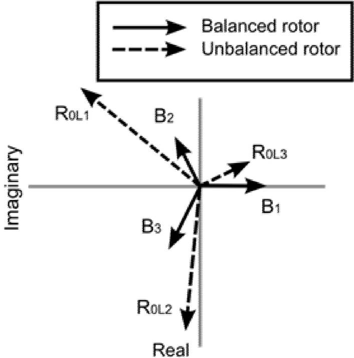
When direct measurements are included, vectors may look like shown in Figure 4 and their equations are:
 (3)
(3)
 (4)
(4)
 (5)
(5)

In order to obtain the absolute phase angles, the algorithm uses the relative phase angles among vectors P 0L1 , P 0L2 , P 0L3 obtained by measurement. It then iterates until vectors R 0L1 , R 0L2 , R 0L3 reach 120° between each other, satisfying the following conditions:
 (6)
(6)
There is a unique vector combination that fulfills this condition, and thus the absolute phase angles are determined.
Traditional balancing
Having determined the harmonic phases, it is possible to calculate the influence coefficients as well as the balance masses for each combination of trial weights. In the traditional method of influence coefficients, formulas (7) and (8) provide a balance mass assuming the magnitude and phase are known.
 (7)
(7)
 (8)
(8)
Proposed balancing method
From equations (3) and (4), it gets:
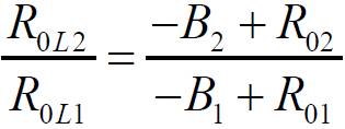 (9)
(9)
Besides

Substitution in equation (9) yields the following result:
 (10)
(10)
Let the following transformation:
 (11)
(11)
Substituting gives:
 (12)
(12)
This expression represents a circle with center at

And the radius is:

The circle C + Re
iθ′
represents the geometric locus of all possible relations R
0L2
/R
0L1
and the correct value
Similarly there is another circle C + Re
iθ′′
which represents the geometric locus of all possible relations R
0L3
/R
0L1
and the correct value
If errors are present, harmonics must be adjusted by the following perturbations:
 (13)
(13)
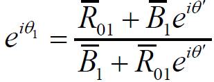
Next, a set of relations involving perturbations is developed: from equation (12), equating the right side to the correct relation yields:
 (14)
(14)
This means that there must be a parameter θ′ that corresponds to the correct point. This is a compatibility condition for harmonics related with L 1 , L 2 .
By expressing this equation in rectangular form, it is obtained the following:

Equating the real and imaginary parts of both sides of last equation, one gets:
 (15)
(15)
Solving this system of equations yields:
 (16)
(16)
 (17)
(17)
Substituting in the trigonometric identity that the sum of the squares is equal to one, one gets:

Substituting these coefficients the following expression is obtained:
 (18)
(18)
Similarly, for the circle corresponding to θ′′ the following are obtained:
 (19)
(19)
 (20)
(20)
 (21)
(21)
In order to satisfy (18) and (21), which implies θ′=θ′′, ie. sinθ′=sinθ′′, it is necessary to adjust all parameters involved by means of small perturbations leading to (22), where h i are not described here for lack of space. By similar procedure, for the relation, cosθ′ = cosθ′′ we obtain equation (23)
 (22)
(22)
 (23)
(23)
Similarly, equations (18) and (21) are worked out to satisfy themselves by perturbing the harmonics to finally obtain (24) and (25).
 (24)
(24)
 (25)
(25)
Since the parameter θ′ is going to vary in an iterative process, the following constant is defined: S tp = sinθ′ and it is substituted in equation (16) and harmonics are perturbed to get equation (26).
 (26)
(26)
Similarly, we define C tp =cosθ ' , substitute in equation (17) and apply perturbations to obtain (27).
 (27)
(27)
Equating (22) and (23) one gets:
 (28)
(28)
Substitution of equation (28) in (22) gives:
 (29)
(29)
Substitution of equation (28) and (29) in (25) gives:
 (30)
(30)
Substitution of equation (29) in (24) gives:
 (31)
(31)
Thus all perturbations are expressed in terms of ε2.
These are substituted in equations (26) and (27) to obtain two expressions of ε2:
 (32)
(32)
 (33)
(33)
In the iterative process, when the parameters θ′, θ′′ approach each other, so do both values of ε2 given by equations (32) and (33). At the end, the desired solution is obtained for the given value of θ′.
To illustrate this procedure, the following exercise is conducted for one test case. Here, parameter θ′ is varied from 0° to 360° and a circle related to R
0L2
/ R
0L1
is plotted before perturbations to harmonics are applied. This is shown in Figure 5 where the point


As it may be seen, perturbations are enforcing data to fulfill compatibility conditions by making the circle pass over the “exact point”. Something similar applies to the other circle of R
0L3
/ R
0L1
and its “exact point”
To determine which θ′ to use for this rotor balancing, either for the original balance run or for the trial mass run, the following analysis is performed.
The inertia force due to the unbalance mass plus the trial mass is the resultant:

By taking the real and imaginary parts of this vector equation one gets:

This may be written in a matrix form:
 (34)
(34)
Given the unbalance and resultant angles (according to the iterations), and the trial mass, the magnitudes of the unbalance mass and the resultant may be solved as follows:
 (35)
(35)
The angle of transformation for the original unbalanced condition
 (36)
(36)
Equations (35) and (36) provide another compatibility condition that allows the determination of the desired solution to the balancing problem.
Algorithm description
The numerical procedure consists of the following steps:
It initiates the iteration cycle for the parameter
It initiates another iteration cycle for the parameter θ′ corresponding to the trial mass run. It then calculates the harmonics R 01, R 02, R 03 related to the resultant unbalance. This is performed in a similar way as the previous step.
Once the harmonics are known, it then calculates the influence coefficients and the balance masses.
It initiates an iteration cycle for the unbalance angle, calculating then the unbalance mass according to equation (35). Iteration is done until it finds the best approximation to the unbalance mass obtained previously in step 3.
It recycles iteration to step 2.
It recycles iteration to step 1. At the end, it brings out the optimal solution of the parameters, and the desired balance mass.
Applications
Several tests were conducted using an induction motor described in Table 1. Recorded data using the virtual instrument described above are shown in Tables 2 and 3. Table 4 shows estimated balance masses for each test case to compare with the expected value.


These test results show that balance mass approaches the expected value with an error of less than 10% in magnitude and with +/- 10° error in angular position.
As is well known in rotor balancing, vibration data is subject to random errors which make the first balancing exercise not precise enough in terms of fulfilling the vibration standards for the particular rotor in turn. Normally, it is necessary to conduct a second exercise called “trimming” that reduces any residual unbalance.
The balance technique that is presented here is unique in handling residual current as input data, and it is also subject to measurement errors. The test cases show the first balancing exercise where the estimated balance masses have relatively small errors similar to the ones obtained in traditional practice.
Conclusions
Based on previous works in the literature, where a relationship between the mechanical unbalance and the electric-current harmonics is reported, this article develops a more efficient method of balancing that takes into account the r.m.s. values of these harmonics and the relative phase angles among the three frequency lines.
This balancing technique faces two problems; one is data variations of samples which are solved by taking three to five minute samplings, and calculating the r.m.s. value of the response. The other difficulty is nonlinearity behavior of data due to an offset.
The magnitudes of the signal spectrum do not have a linear homogeneous relationship with the unbalance force due to a complex offset that can be measured with the balanced rotor, and that adds to the unbalance effects. These vectors are measured in magnitude, and their measured phase angles are relative.
The harmonics of the balanced-rotor condition are determined in magnitude, and their phase angles are set to 0°, −120° y −240° for the corresponding line frequency Li, in the case of low frequency (h l ). For high frequency (h h ) the relative angles are set to 0°.
The harmonics related to the unbalance condition (vectors P 0L1 , P 0L2 and P 0L3 ) have an absolute phase that is iteratively calculated depending on the parameter α1, which is the absolute phase angle of line L 1 and taking into account the relative phase with the other frequency lines.
The numerical procedure consists of iterations of angles of transformation
The test cases show that the calculated balance mass approaches the expected value with an error of less than 10% in magnitude and with
The virtual instrument developed in this work offers a low cost and a user-friendly interface, and thus a remarkable potential for industrial applications.

