


 nueva página del texto (beta)
 Inglés (pdf)
 Artículo en XML
 Referencias del artículo
 Enviar artículo por email
 Citado por SciELO
  Similares en
SciELO
Similares en
SciELO 
 Permalink
1. Introduction
In 1987, Eli Yablonovitch and Sajeev John proposed Photonic Band-Gap (PBG) structures, which uses metal ground plane, and breaks with the traditional design of microstrip antennas. The PBG structure is a periodic structure, which inhibits the energy propagation in certain frequency bands. However, it is difficult to use it in the design of components of microwave and millimeter-wave, due to the difficulties in modeling (Weng 2008, 173). Defected Ground Structure (DGS) can be described as an Electromagnetic Band-Gap (EBG) unit cell, as it is mentioned in (Debatosh 2011, Chapter 12), where the resonant nature of DGS slots are also discussed. The DGS is a simple and powerful variant of the PBG structure, where a part of the microstrip circuit ground plane, is intentionally modified to improve the performance of the antenna (Kumar 2013, 589).
DGS or slotted ground planes are used in (Jaswinder 2013, 1) to achieve dual-band operation with appreciable impedance bandwidth, producing a novel multistrip monopole antenna fed. Fractal case for improving Bandwith has also been considered (Varun 2014, 162). In (Kamariah 2012, 421; Hussain, 2014, 2367), DGS are used to improve the electrical performance of an antenna as well as reducing its dimension. DGS is also used to reduce the cross-polarized (XP) radiation of a microstrip patch antenna (Debatosh 2005, 455). DGS tend to lessen the surface waves and consequently increase the antenna efficiency. They are also used to enhance the properties of the microstrip antenna structure proposed in (Oraizi 2010). There is a wide variety of geometries that can be etched as DGS, such as arrow tip, spiral, H shape, etc., (Garg 2014, 1285; Jaswinder 2013, 1; Pozar 1995, 269; Kumar 2013, 589).
Some general applications of DGS are also described in (Pozar 1995, 269). Specific applications can be found in (Debatosh 2011, Chapter 12; Ashwini 2010, 79; Breed 2008, 50; Jong-Sik 2004, 52).
In this work, the interest is focused on the effect of rectangular and circular defects on ground planes. Designs were realized using FR-4. The antennas design and simulation results will be provided in section II. The corresponding discussion of results is given in section III. Finally, in section IV, some concluding remarks are given.
2. Antennas design
The rectangular patch antenna was designed at 2.4 GHz, using the following equations (Balanis 2005; Garg 2001). For the patch width calculation:
 (1)
(1)
Where c is the constant speed of light in vacuum, εr the dielectric constant substrate and f0, the operating frequency. The effective dielectric constant is given by:
 (2)
(2)
The effective length is calculated using:
 (3)
(3)
The two increments in the length, which are generated by the fringing fields, make electrical length slightly larger than the physical length of the patch:
 (4)
(4)
The patch length is given by:
 (5)
(5)
2.1 Rectangular ground plane design with and without DGS
The length and width of ground plane (and substrate), L g and W g are:
 (6)
(6)
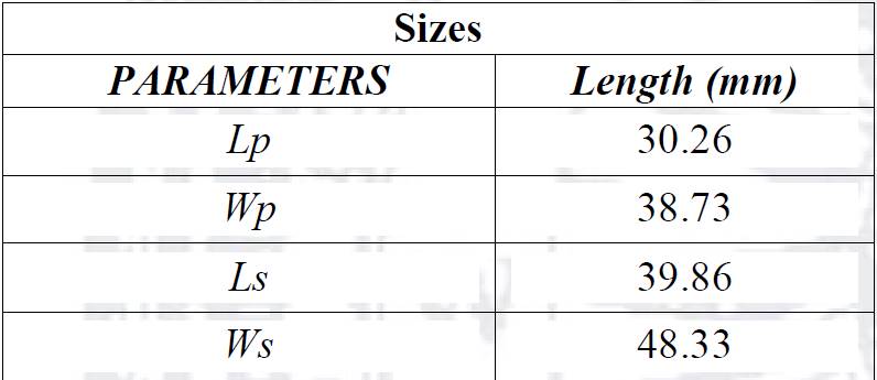
The calculated sizes of the individual rectangular patch antenna (Figure 1), are shown in Table 1. The height of the substrate is h=1.6 mm. and εr= 4. Cuts on the corners of the rectangular antenna are implemented in order to increase its gain, with a depth of λg/16 (M. Tecpoyotl-Torres 2013, 1), where λ g =c/(f o *√ε reff ) is the wavelength group. These data are used in simulations.
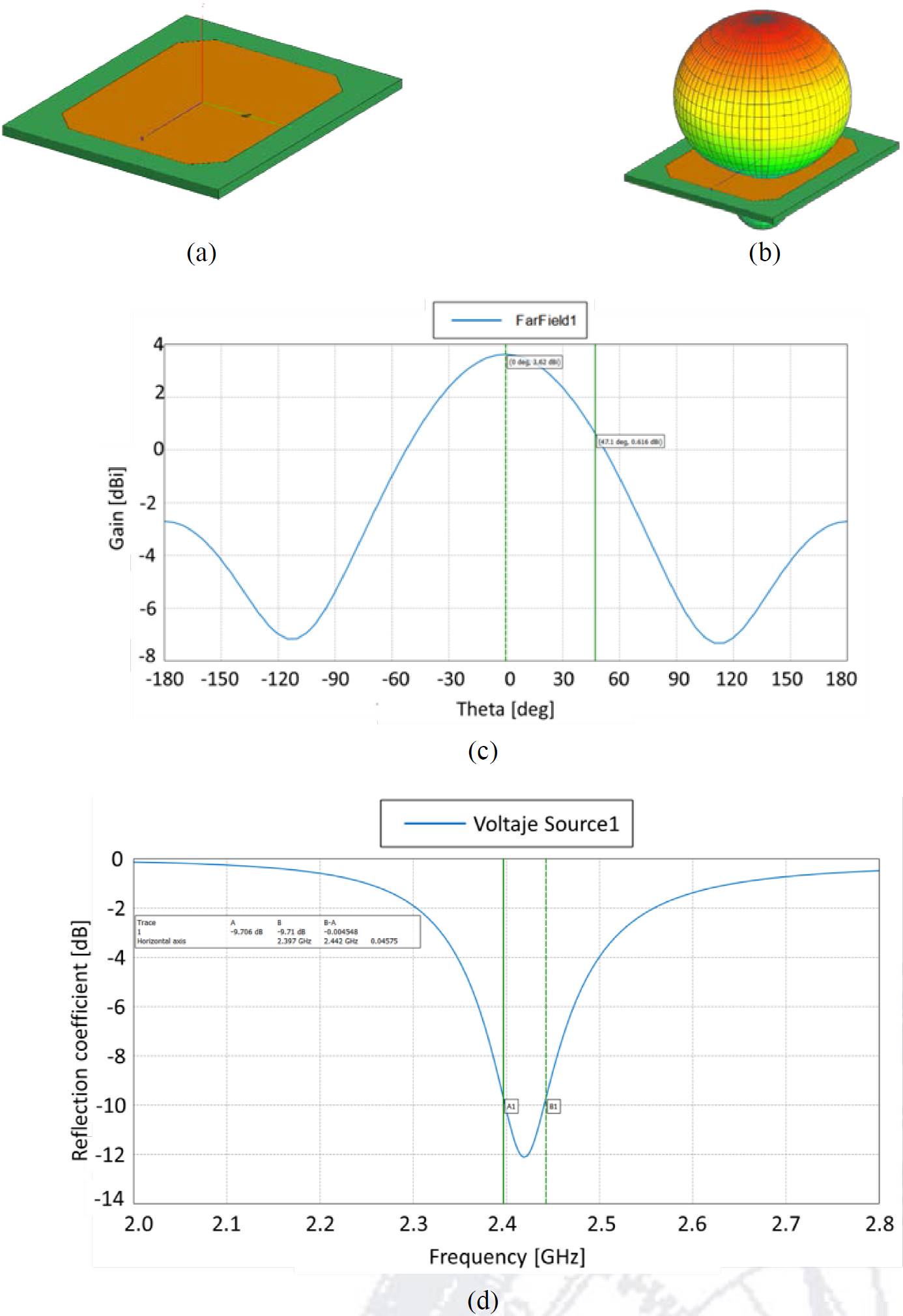
Fig. 1. (a) Rectangular patch antenna. (b) 3D gain. (c) Graph of gain with a maximum value of 3.62 dBi. (d) Parameter S11 with a minimum value of -12.2 dB. The BW is 45.75 MHz.

2.1.1. Circular DGS under rectangular substrate
A series of defects were implemented on the corresponding substrate. The DGS were implemented under the corners of the radiating patch. These locations were chosen because the bigger losses are generally given on the patch corners. However, the case of a central defect was also implemented in the middle part of the four DGS, but the results do not show changes in comparison with the case without it. The sizes of all DGS were given in fractions of λ g in order to simplify their implementation at other frequencies and materials with different thickness and effective permittivities.

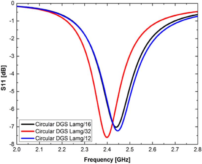
Fig.2. (a) Rectangular patch antenna with 4 circular defects on substrate, with radius of λ g /16. (b) 3D gain.
Ratios of value λ g /12 and λ g /32 of circular shape DGS were also implemented under the corners of the radiating patch in order to observe the effect of this parameter of length. Gain and S11 parameter have similar response in these cases. The value of S11 parameter is above to -9.57 dB, which is the biggest value for good antenna performance.

2.1.2. Circular DGS under rectangular substrate
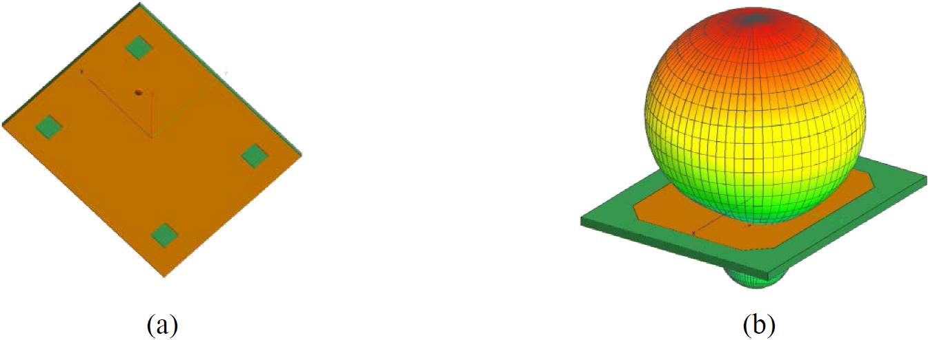
Fig.5. (a) Rectangular patch antenna with 4 square defects on substrate, with sides lengths of λ g /16. (b) 3D gain.

Fig.6. (a) Rectangular patch antenna with 4 square defects on substrate, with sides lengths of λ g /8. (b) 3D gain.
Figure 7 shows a comparison of S11 parameter for three cases, where length sizes of squares DGS are varied. Figure 8 shows the gain values comparison.

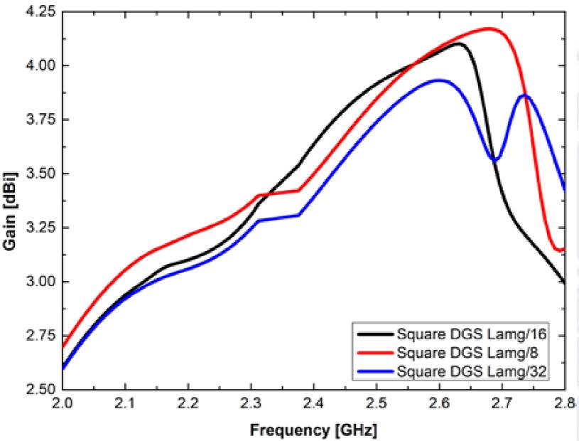
For the square DGS with side length of λ g /8, a slightly better performace is obtained. Differences in gain and in the S11 parameter are small for both cases.
2.1.3 Rectangular DGS under rectangular substrate
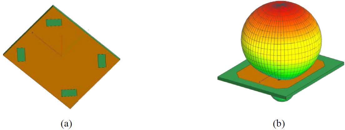
Fig. 9. (a) Rectangular patch antenna with 4 rectangular defects on substrate, normal to corners, with side’s lengths of λ g /16 and λ g /8. (b) 3D gain.

Fig.10. (a) Rectangular patch antenna with 4 thin rectangular defects on substrate, normal to corners, with sides lengths of λ g /32 and λ g /8. (b) 3D gain. (c) Graph of gain with a maximum value of 3.66 dBi. (d) Parameter S11 with a minimum value of -28 dB. The BW is 55.15 MHz.
In Figures 11 and 12, the S11 parameter and the gain are presented respectively. In order to analyze the difference with other geometries and different sizes.

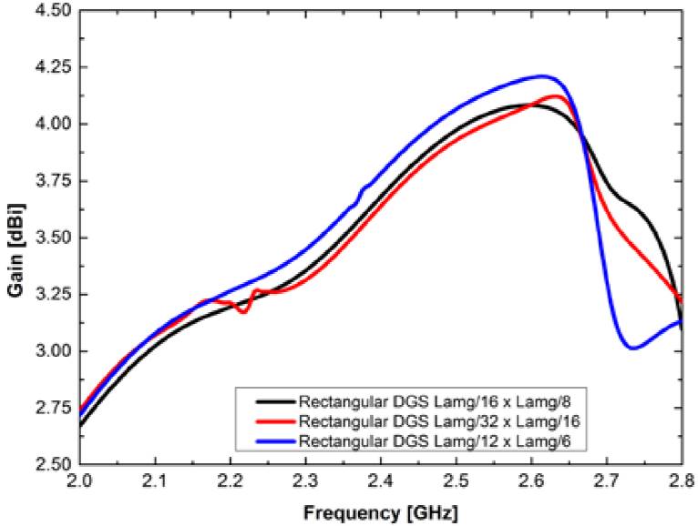
In the case of rectangular defects under the substrate, the gain behaves very similarly in all three cases with different lengths. The best performance corresponds to the case of rectangular defect with lengths sides of λ g /12 and λ g /8. However in S11 graph, the best performance was determined for rectangular defect with lengths sides of λ g /12 and λ g /6. Differences are slightly, each case could be useful.
In Table 2, a comparison of bandwidth for all analyzed geometries is provided.

From Table 2, it can be observed that when a large bandwidth is required, the best geometry to implement is those with a circular or square geometry with a ratio of λ g /32 or legth side of λ g /8, respectively.
The increment on BW, considering the case without DGS is of 25.61%.
S11 appropriate parameters were obtained for the case of square and rectangular DGS.
2.2 Circular ground plane with and without DGS
The radiant patch size, presented in Table 1 is used on a circular substrate of FR-4, in order to analyze the effect of DGS on the antenna performance (Figure 13).

Fig. 13. (a) Rectangular patch antenna with circular substrate. (b) 3D gain. (c) Graph of gain with a maximum value of 4.41 dBi. (d) Parameter S11 with a minimum value of -10.8 dB. The BW is 28.82 MHz.
The separation between patch and substrate was considered again as 6h (3h, perpendicular to the corner cut to the edge of the ground plane). Distance from the center to the edge of the ground plane was calculated on the coordinate axes (abscissa and ordinate), as 19.56 mm and 26.41 mm, respectively.
In Figure 14, the results of circular DGS implementation are shown. It was the unique geometry analyzed because it gives the bigger gain value after the previous subsection.

Fig. 14. (a) Circular DGS with radius of λ g /16. (b) 3D gain. (c) Graph of gain with a maximum value of 4.74 dBi. (d) Parameter S11 with a minimum value of -26 dB. The BW is 57.03 MHz.
In Table 3, a resume of results of the analyzed parameters is provided for all cases.

Comparison between rectangular antenna on rectangular and circular substrate shows without DGS:
Bigger gain value of circular case in 21.82%.
The bandwidth for rectangular case is bigger than circular one in 38.09%. The S11 parameter is smaller for the case of rectangular substrates (11.47%). For applications which require bigger gain, circular substrate is recommended, but for bigger bandwidth, rectangular case is suggested.
The employment of DGS in both cases, provides and improvement in analyzed parameters, except for the case of S11 for rectangular substrate and curcular DGS.
About the use of different geometries of DGS provides the following results:
Using DGS, for rectangular substrate:
Circular DGS provides a slightly increment on gain value.
For the case of rectangular DGS, in both positions slightly increments on parameters values were obtained for the case of bigger sizes of DGS. The case of DGS parallel to rectangular substrate sides provides a slightly bigger value than perpendicular case.
A notable decrement in S11 parameter is obtained, which represents an advantage.
Using DGS, for circular substrate: An increment in bandwidth is considerable larger than in the case without DGS, and a reduced value of S11.
3. Discussion of simulation results
For the case of rectangular patch antenna on rectangular substrate of FR-4, the implementation of defects shows in all considered cases a small increment on the gain, and a considerable improvement on S11 parameter, from -12.2 dB without DGS to -57.47 dB with circular and square DGS. But, for circular DGS, the S11 parameter has bigger values.
Circular substrate case on FR-4 shows a narrow response of 28.32 MHz (Figure 13), and a considerable increment in BW when circular DGS are obtained (57.03MHz). Equivalent to an increment of 113.59%, bigger than the case of rectangular substrate without defects. An increment on gain value compared to the rectangular substrate was also obtained at least of 21.82%.
4. Conclusions
From the obtained results for rectangular antennas on two substrate geometries, realized on FR-4, it can be concluded that:
Without DGS: A bigger gain (21.82%) corresponds to circular substrate, but lower bandwidth (38.09%), compared to the rectangular one.
For rectangular antenna on rectangular ground plane with DGS:
The use of DGS improves considerably the S11 parameter value for square and rectangular shapes comparing with the case without DGS on rectangular substrate of FR-4.
The use of cuts on the corners increment the gain value, but decreases the S11 parameter value, the use of DGS compensates this decrement.
For rectangular antenna on circular ground plane, only circular DGS was implanted, due to these geometries gave bigger gain value in all DGS geometries considered for rectangular substrate. The advantage of the circular DGS on circular substrate was an increment of 113.59% on the Bandwidth value.
The analysis of the same implemented geometries on other materials is recommended.

