


 text new page (beta)
 Spanish (pdf)
 Article in xml format
 Article references
 Send this article by e-mail
 Cited by SciELO
  Similars in
SciELO
Similars in
SciELO 
 Permalink
Nomenclature
 the thermal expansion coefficient of FeB layer (
 ).
).
 the thermal expansion coefficient of
  layer ().
 boride layer thickness (
 ).
).
 is rate constant in the phase (
 ).
).
 is the effective growth time of the layer (
 ).
).
 is the treatment time ().
 is the boride incubation time ().
 the activation energy of the system (
 ).
).
 represents the upper limit of boron content in (
 ).
).
 is the lower limit of boron content in (
 ).
).
 is the adsorbed boron concentration in the boride layer (
 ).
).
 defines the homogeneity range of the layer (
 ).
).
 is the miscibility gap ().
 is the terminal solubility of the interstitial solute (
 ).
).
 is the boron concentration profile in the layer ().
 is the error function (it has no physical dimensions).
 indicates the initial layer ().
 is the normalized growth parameter for the (/substrate) interface (it has no physical dimensions).
 denotes the diffusion coefficient of boron in the phase (
 ).
).
 are the fluxes of boron atoms in the (/substrate) inter face boundary (
 ).
).
1. Introduction
Boriding is a well-known thermochemical treatment in which boron (because of its relatively small size) diffuses into the metal substrate to form hard borides. As a result of boriding, properties such as wear resistance, surface hardness and corrosion resistance are improved Sinha 1991 , 437 -438). Boriding can be carried with boron in different states such as solid powder, paste, liquid, gas and plasma. The most frequently used method is pack-boriding owing to its technical advantages Meric et al. 2000 , 2168-2169). Generally, the commercial boriding mixture is composed of boron carbide (B4C) as donor, KBF4 as an activator and silicon carbide (SiC) as a diluent to control the boriding potential of the medium. The boriding treatment requires temperatures ranging from 800 to 1000°C. Usually the treatment time varies between 0.5 and 12 h producing a boride layer of thickness depending on the boriding parameters (time and temperature). The morphology of the boride layer is affected by the presence of alloying elements in the matrix. Saw - tooth shaped layers are obtained in low -alloy steels or Armco iron whereas in high-alloy steels, the interfaces are smooth. According to the Fe-B phase diagram Okamoto 2004 , 297), two iron borides can be formed (FeB and ).
A monophase layer with a tooth-shaped morphology is generally suitable for industrial application owing to difference between the specific volume and coefficient of thermal expansion of boride and the substrate Vipin 2002 , 21-22)( Pertek 2002 , 256-258). The boron rich phase FeB is not preferred since FeB is more brittle and less tough than (Vipin 2002, 21-22)(Pertek 2002, 256-258). Furthermore, the brittleness of FeB layers causes a spalling when a high normal or tangential load is applied.
The modeling of the boriding kinetics is considered as a suitable tool to select the optimized parameters for obtaining a desired boride layer of the treated material for its practical use in industry. In particular, many models were reported in the literature for analyzing the growth of layers grown on different substrates (Campos et al. 2003, 264-266) ( Keddam et al. 2010 , 5028-5029) with and without the boride incubation times.
AISI 1026 steel is used on automotive industry to manufacture shaft and forged parts, but an improvemet on its wear properties is required. For this steel, a new diffusion model to stimate the borided layers is proposed with a just incubation time. Thus, on the current work, a diffusion model based on solving the masse balance equation at the (/ substrate) interface was proposed to simulate the growth kinetics of layers grown on AISI 1026 steel. In the present model, the boride incubation time was taken independent on temperature. The pack-borided AISI 1026 was characterized by means of the following techniques: (optical microscopy, scanning electron microscopy, XRD and the Daimler-Benz Rockwell-C indentation technique). Based on experimental data, the boron activation energy was also evaluated when pack-boriding the AISI 1026 steel in the temperature range of 1123-1273 K.
2. Method
2.1 The kinetic model
The model takes into account the growth of layer on a saturated substrate with boron atoms as illustrated in Figure 1.
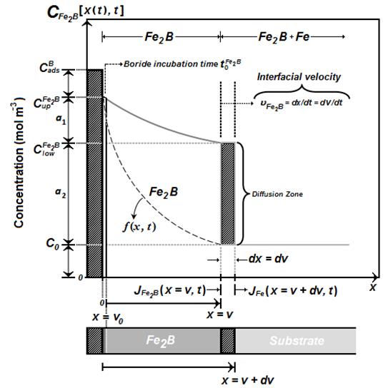
The  function represents the boron distribution in the ferritic matrix before the nucleation of phase.
  corresponds to the incubation time required to form the phase when the matrix reaches a saturation state with boron atoms. represents the upper limit of boron content in (
 ) Kulka et al. 2013 , 197-199), is the lower limit of boron content in (
 ) and the point
  represents the layer thickness, see Figure 1, Brakman et al. 1989 , 1357-1359).
The term is the effective adsorbed boron concentration during the boriding process Yu et al. 2005 , 2364-2365). From Figure 1, defines the homogeneity range of the layer,  is the miscibility gap and is the boron solubility in the matrix. This diffusion zone in the substrate underneath the compound layer can be ignored (
 ) Okamoto 2004 , 297). The following assumptions are considered for the diffusion model:
The growth kinetics is controlled by the boron diffusion in the
layer.The
iron boride nucleates after a specific incubation time.The boride layer grows because of the boron diffusion perpendicular to the specimen surface.
Boron concentrations remain constant in the boride layer during the treatment.
The influence of the alloying elements on the growth kinetics of the layer is not taken into account.
The boride layer is thin compared to the sample thickness.
A uniform temperature is assumed throughout the sample.
Planar morphology is assumed for the phase interface.
The initial and boundary conditions for the diffusion problem are represented as:

Boundary conditions:
is a thin layer with a thickness of  nm formed during the nucleation stage (Dybkpv 2010, 7). Thus,
  when compared to the thickness of layer (). The mass balance equation at the (/substrate) interface can be formulated by Equation (4) as follows:

Where  is defined as the unit area and
  represents the boron concentration in the matrix. The flux
  and
and  are obtained from the Fick's First law as:

and

The term is null since the boron solubility in the matrix is very low ( mol m-3 )Okamoto 2004 , 297).
Thus, Eq. (4) can be written as:
If the boron concentration profile in is constant for the treatment time, Fick's Second law is reduced to an ordinary second-order differential equation as follows:

By solving Eq. (8), and applying the boundary conditions proposed in Eqs. (2) and (3), the boron concentration profile in is expressed by Eq. (9) if the boron diffusion coefficient in is constant for a particular temperature :
By substituting Eq. (9) into Eq. (7), equation (10) is obtained:
for  .
.
Substituting the expression of the parabolic growth law: ( ) into Eq. (10), Eq. (11) is deduced:

The normalized growth parameter () for the (/substrate) interface can be estimated numerically by the Newton-Raphson method. It is assumed that expressions , , and
  , do not depend significantly on temperature (in the considered temperature range) (Brakman et al. 1989, 1357-1359).
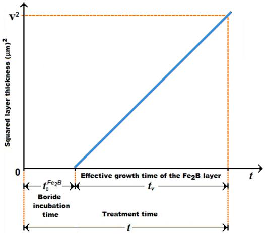
A schematic representation of the square of the layer thickness against linear time ( ) is depicted in Figure 2.
  is the effective growth time of the layer and is the treatment time.
2.2. Experimental procedure
2.2.1. The boriding process
The material to be borided is AISI 1026 steel. It has a nominal chemical composition of 0.22-0.28 % C, 0.60-0.90% Mn, 0.07-0.6% Si, 0.050% S, and 0.040% P. The samples have a cubic shape with dimensions of  Prior to the boriding process, the specimens were polished, ultrasonically cleaned in an alcohol solution and deionized water for 15 min at room temperature, and dried and stored under clean-room conditions.
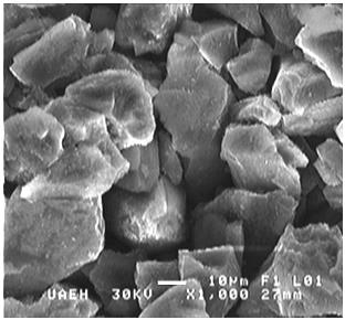
The samples were packed along with a Durborid fresh powder mixture in a closed cylindrical case (AISI 304L) as shown in Figure 3. This powder mixture has an average size of 30 μm as illustrated on Figure 4.
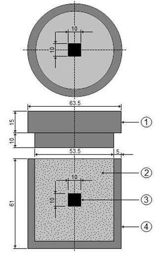
Figure 3 Schematic view of the stainless steel AISI 304L container for the pack-powder boriding treatment (1: lid; 2: powder boriding medium (B4C + KBF4 + SiC); 3: sample; 4: container).
The powder-pack boriding process was carried out in a conventional furnace under a pure argon atmosphere in the temperature range of 1123 -1273 K. Four treatment times (2, 4, 6 and 8 h) were selected for each temperature. After the completion of boriding treatment, the container was removed from the furnace and slowly cooled to room temperature. As a result of preliminary experiments it was estimated that boriding started  approximately after transferring the specimen to the furnace; after that, the so-called boride incubation time sets in.
2.2.2. Microscopical observations of boride layers
The borided samples were cross-sectioned for metallographic examinations using a LECO VC-50 cutting precision machine. The cross-sectional morphology of the boride layers was observed with the Olympus GX51 optical microscope in a clear field. Figure 5 shows the cress-sectional view of optical images of the layers of AISI 1026 steel formed at a temperature of 1173 K for different process durations. The resultant microstructure of layers appears to be very dense and homogenous, exhibiting a saw-toothed morphology. Since the growth of the saw-toothed boride layer is a controlled diffusion process with a highly anisotropic nature, higher temperatures and/or longer times encouraged the crystals to make contact with adjacent crystals and forced them to retain an acicular shape Palombarini - Carbucicchio 1987 , 417). It is seen that the thickness of layer increased with an increase of the boriding time (Figure 5) since the boriding kinetics is influenced by the treatment time Campos-Silva et al. 2013 , 415). For a kinetic study, the boride layer thickness was automatically measured with the aid of MSQ PLUS software (Ortíz-Dominguez, 2013). To ensure the reproducibility of the measured layers thicknesses, fifty measurements were collected in different sections of the borided AISI 1026 steel samples to estimate the layer thickness; defined as an average value of the long boride teeth Campos-Silva 2010 , 410). All thickness measurements were taken from a fixed reference on the surface of the borided AISI 1026 steel, as illustrated in Figure 6.
Figure 5 Optical micrographs of the boride layers formed at the surface of AISI 1026 steel treated at 1173 K during a variable time: (a) 2, 4, 6 and (b) 8 h.
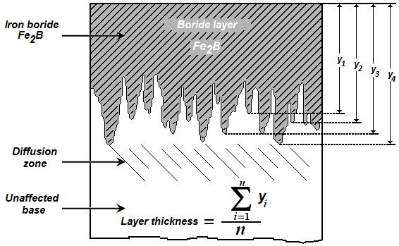
Figure 6 Schematic diagram illustrating the procedure for estimation of boride layer thickness in AISI 1026 steel.
The phases of the boride layers were investigated by an X-Ray Diffraction (XRD) equipment (Equinox 2000) using  radiation of 0.179 nm wavelength. The elemental distribution within the cross-section of boride layer was determined by Electron Dispersive Spectroscopy (EDS) equipment (JEOL JSM 6300 LV) from the surface. The Daimler-Benz Rocwell-C was performed to attain qualitative information on the adhesive strength of the boride layers to the substrate (Verein, 1991, 4). The well-known Rockwell-C indentation test is prescribed by the VDI 3198 norm, as a destructive quality test of coated compounds Vidakis et al. 2003 , 483). The principle of this method was reported in the reference work Taktak 2007 , 1837 - 1839). A load of 1471 N was applied to cause coating damage adjacent to the boundary of the indentation. Three indentations were conducted for each borided sample and scanning electron microscopy (SEM) was used to assess the adhesion test.
3. Results and discussions
3.1. SEM observations and EDS analysis
The cross- sectional view of SEM micrograph obtained on the borided AISI 1026 steel at 1223 K for 8 h, is shown in Figure 7(a). The boride layer is grown on the substrate with a saw- toothed morphology. The needles of, with a difference in length, are visible on the SEM micrograph and penetrating into the substrate. This typical morphology is responsible of a good adhesion to the substrate. On this point, is important to know the behavior of the others alloy elements, as such Mn, Si, in the interphase and surface of the boride layer as explained ahead by an EDS analysis.
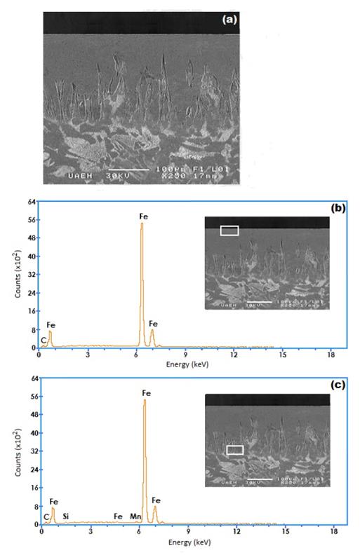
Figure 7 (a) SEM micrographs of the cross-sections of the borided AISI 1026 steel at 1223 K for 8 h, (b) EDS spectrum of borided sample at surface and (c) EDS spectrum of borided sample at interface.
The cross section of SEM micrograph of the AISI 1026, borided at temperature of 1223 K for 8 h, is shown in Fig. 7(a). The EDS analysis obtained by SEM is shown in Fig. 7(b) and (c) . The amounts of manganese appear to be lower than that of iron in the boride layer because of lower solubility. Thus, the deficiency of Mn results in a negative effect on the boride layer in terms of both thickness and morphology.
Fig. 7(c) shows that the carbon and silicon do not dissolve significantly over the phase and they do not diffuse through the boride layer, being displaced to the diffusion zone, and forms together with boron, solid solutions like silicoborides ( and
and  ) and boroncementite (
 ) [28].
3.2 X-ray diffraction analysis
Figure 8 shows the XRD pattern recorded on the surface of borided AISI 1026 steel at a temperature of 1273 K for a treatment time of 8 h. The diffraction peaks relative to the  phase are easily identified.
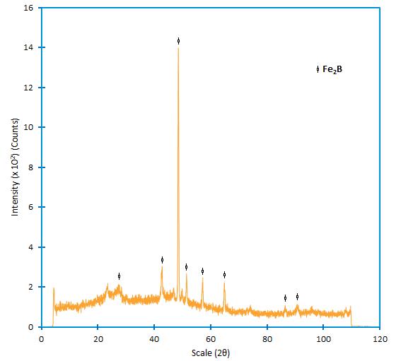
Figure 8 XRD pattern obtained at the surface of the borided AISI 1026 steel treated at 1273 K for 8 h, where the mains Fe2B peaks are showed.
Crystals of the type orientate themselves with the z-axis perpendicular to the surface. Consequently, the peaks of the phase belonging to crystallographic planes, having a deviation from zero of the l index, showed increased intensities in the X-ray diffraction spectra Badini y Mazza 1988 , 663-665). The growth of boride layers is a controlled diffusion process with a highly anisotropic nature. In case of the phase, the crystallographic direction [001] is the easiest path for the boron diffusion in , because of the tendency of boride crystals to grow along a direction of minimum resistance, perpendicular to the external surface. As the metal surface is covered, an increasing number of crystals comes in contact with adjacent crystals and are forced to grow inside the metal, retaining an acicular shape Palombarini - Carbucicchio 1987 , 415). In the powder-pack boriding, the active boron is supplied by the powder mixture. To form the phase on any borided steel, a low boron potential is required as reported in the reference works Vipin 2002 , 21-22) ( Bindal y Ucisik 1999 , 209-211), where a high amount of active boron in the powder mixture gives rise to the bilayer configuration consisting of FeB and .
3.3 Rockwell-C adhesion test
An indenter hardness tester was used to assess the Daimler-Benz Rockwell-C adhesion, as a destructive quality test for examined layers, it was employed for determination of cohesion. The well-know adhesion test prescribed by the VDI 3198 norm was used (Verein, 1991, 4). The principle of this method was presented in Figure 9. A conical diamond indenter penetrated into the surface of an investigated layer, thus inducing massive plastic deformation to the substrate and fracture of the boride layer.
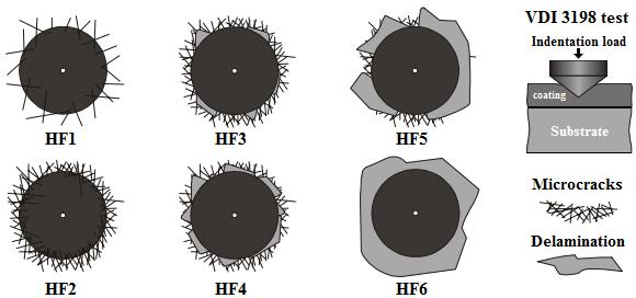
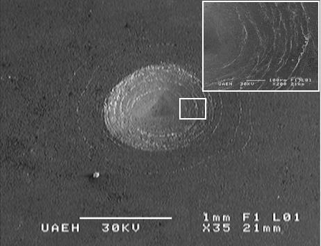
The damage of the boride layer was compared with the adhesion strength quality maps HF1-HF6 (see Figure 9). In general, the adhesion strength HF1 to HF4 defined sufficient adhesion, whereas HF5 and HF6 represented insufficient adhesion (Verein, 1991, 4). Scanning Electron Microscope (SEM) images of the indentation craters for samples borided at 1273 K for 4 h are given in Figure 10. The indentation craters obtained on the surface of the borided AISI 1026 revealed that there were radial cracks at the perimeter of indentation craters. However, a small quantity of spots with flaking of delamination was visible and the adhesion strength quality of this boride layer fits the HF3 category. In this context, the authors S. Taktak and S. Tasgetiren (2006, 571-572) have used the Daimler-Benz Rockwell-C adhesion technique to study the adhesion of boride layers grown on AISI H13 and AISI 304 steels. They found that their adhesion decreased with an increase of boriding time and temperature. Rodriguez et al. (2009, 63) also reported the adhesive strength of the boride layers using Daimler-Benz method.
3.4 Estimation of boron activation energy
The growth kinetics of layers formed on the AISI 1026 steel was used to estimate the boron diffusion coefficient through the layers by applying the suggested diffusion model. The determination of epsilon parameter ( ) is then required by solving the mass balance equation at the (/substrate) interface (see Eq. (11)) using the Newton-Raphson method. The time dependence of the squared value of layer thickness is shown in Figure 11. The slopes of the straight lines in this figure provide the values of growth constants
  for each boriding temperature. The value of boron diffusion coefficient in the layers can be determined by knowing the value of epsilon parameter. The boride incubation times for can also be deduced from the straight lines displayed in Figure 11 by extrapolating to a null boride layer thickness.
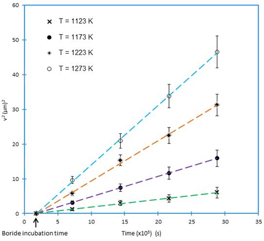

Table 1 summarizes the estimated value of boron diffusion coefficient in at each temperature along with the squared normalized value of epsilon determined from Eq. (11).
Table 1 The squared value of normalized growth parameter and boron diffusion coefficients in Fe2B as a function of boriding temperature.
To estimate the boron activation energy for the AISI 1026 steel, it is necessary to plot the natural logarithm of boron diffusion coefficient in versus the reciprocal temperature following the Arrhenius equation (see Figure 12). A linear fitting was adopted to obtain the temperature dpendence of boron diffusion coefficient in with a correlation factor of 0.9782.


where:  and
and  absolute temperature
  .
.
Table 2 shows a comparison of the boron activation energies in case of some borided steels (Celik et al. 2008, 33-336) (Gunes et al. 2013, 569-570). The found value of boron activation energy (= 178.4 kJ mol -1) for AISI 1026 is slightly different from the reported value in (Gunes et al. 2013, 569-570) depending on the boriding conditions (using the liquid boriding method).

3.5 Validation of the diffusion model
The present model was validated by comparing the experimental value of layer thickness with the predicted result at a temperature of 1253 K for a treatment time of 7 h using Eq. (13):

In Figure 13 is shown the optical image of the boride layer formed at 1253 K for 7 h of treatment.
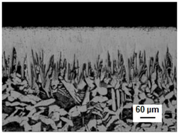
Figure 13 Optical micrographs of boride layer formed on AISI 1026 during powder-pack at the 1253 K of boriding temperature with an exposure time of 7 h.
Table 3 gives a comparison between the experimental value of layer thickness and the predicted one basis of Eq. (13). A good agreement was then obtained between the experimental value of layer thickness and the predicted one for the borided AISI 1026 steel at 1253 K for 7 h.
3.5 Future exploitation of the simulation results
This kinetic approach can be used as a tool to determine the layer thickness as a function of boriding parameters (time and temperature) for AISI 1026 steel. Eq. (13) predicts the layer thickness for any temperature and boriding time. An iso-diagram thickness was plotted as a function of the temperature and exposure time as shown in Figure 14.
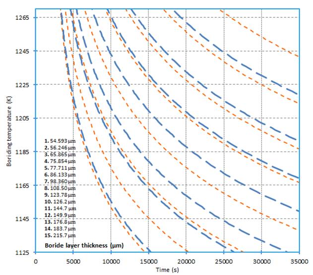
The results of Figure 14 can serve as a powerful tool to select the optimum value of layer thickness in relation with the potential applications of the borided AISI 1026 in industrial scale.
As a rule, thin layers (e.g. 15-20 μm) are used to protect against adhesive wear (such as chipless shaping and metal stamping dies and tools), whereas thick layers are recommended to combat abrasive wear (extrusion tooling for plastics with abrasive fillers and pressing tools for the ceramic industry). In the case of low carbon steels and low alloy steels, the optimum boride layer thicknesses ranges from 50 to 250 μm, and for high- alloy steels, the optimum boride layer thicknesses ranges from 25 to 76 μm. Finally, this model can be extended to predict the growth kinetics of bilayer configuration (FeB + ) grown on any boride steel.
4. Conclusions
The AISI 1026 steel was pack-borided in the temperature range of 1123-1273 K during a treatment time varying from 2 to 8 h. The layers were formed on the AISI 1026 steel substrate. A mathematical model was suggested to estimate the boron diffusion coefficient through the layers. The boron activation energy of the AISI 1026 steel was found to be equal to 178.43 kJ mol1. This value was compared with the data reported in the literature.
The validity of the diffusion model was examined by comparing the experimental value of layer thickness obtained at a temperature of 1253 K for 7 h of treatment with that predicted by the model. In addition, interfacial adhesion of the layers (obtained at 1273 K for 4 h) on AISI 1026 steel substrate was investigated. As a result, it was found that the adhesion strength quality of this boride layer was related to HF3 category according to VDI 3198 norm.

