


 nueva página del texto (beta)
 Inglés (pdf)
 Artículo en XML
 Referencias del artículo
 Enviar artículo por email
 Citado por SciELO
  Similares en
SciELO
Similares en
SciELO 
 Permalink
PACS: 02.20.-a; 42.65.An; 01.30.Bb
1. Introduction
Usually, studying nonlinear optics, one finds tables which have lists of the nonzero coefficients for the second-, third- and even fourth-order susceptibility tensors. A classic text book example regarding this topic is Nonlinear Optics by R. Boyd 1, where it is mentioned that the nonzero coefficients in the tables are calculated using group theory. However, there is no explanation there about the procedure to calculate these coefficients, the author says that such procedure is beyond the scope of the book and refer to the lector to more specialized books in this subject 2,3.
Mathematically, the optical nonlinear response is expressed as a relationship between the polarization P(ω) and the electric field E(ω) In the linear case, the polarization is simply expressed using a proportionality relation
where, the proportionality constant X(1), is the first-order susceptibility and it is an scalar (times the identity tensor), whereas the polarization and the electric field are vectors.
Instead, P(ω) in the nonlinear case can be modeled as a power series of the field E(ω) and is writing in a short form as:
The quantities X(2) and X(3) are known as the second- and third-order susceptibilities, respectively. In contrast, when the electric field is described in a full vectorial way, then in general X(1), X(2) and X(3) are the second, third and fourth rank tensors, respectively.
In the vector formalism, we can write the nonlinear second-order polarization as
or writing the last equation in terms of the components
So the second term in the above equation will be extensively discussed in this manuscript. It is the second-order nonlinear susceptibility and is a third-rank tensor denoted by three subscripts “i”, “j” and “k”.
In order to describe the procedure that is required to calculate the nonzero coefficients in the X(2) tensor for a given set of symmetry operations, a revision of basic concepts is necessary. Therefore, we present in Sec. 2 a brief review of the rotation matrix and also mirror and inversion matrices, with respect to a chosen plane and to one point, respectively. Section 3 discusses the theoretical foundation of group theory. Last part, Sec. 4, explains the procedure to determine the nonzero elements in X(2) for a particular system of reference using group theory. Furthermore, we discuss how to rotate a tensor a general angle around an arbitrary Cartesian axis of rotation, comparing the number of nonzero elements in the tensor in a rotating system of reference with a fixed one. Finally, the conclusions are given.
2. Rotation, mirror and inversion matrices
The standard definition of a rotation matrix in three dimensions, is given by
where the subscript in the matrix R means that the axis of rotation is the z direction and the quantity between parenthesis ϕ, is the angle of rotation. Most of the time, this is the chosen axis of rotation but there are some cases, where a different axis of rotation is used. We are going to give one example of the latter.
In general, according to the symmetry of the crystals and in order to keep the lattice unchanged after a rotation, there are only four possible angles (π, 2π/3, π/2 and π/3) and of course the identity 2π The reason is that the crystal must fill all the space with the periodic repetition of a fundamental building block, therefore only two-, three-, four- and six-fold axis of symmetry exist. However, in the case of molecules or other objects, additional angles of rotation are possible 3.
For a mirror plane, it is understood a reflection using a plane in the same way that a mirror works in real world. Mathematically, this can be expressed in the form of a matrix. For example, when the mirror plane is in the xz plane, it has the form
The minus sign in the matrix element (σx )22 implies a reflection trough the x axis in two dimensions [where the last row and last column in Eq. (6) are inexistent] and in the case of three dimensions; it implies a reflection through the xz plane.
In the same way a mirror plane in the y axis will have, exactly the same form as the matrix shown in Eq. (6) but now the element (σy )11 is the one negative. As the reader may have guessed, for a mirror plane perpendicular to the z axis (in the plane xy), the element (σz )33 now becomes negative. Graphically, the geometrical meaning of the mirror planes is shown in Fig. 1. It is worth to note that for the latter case (Fig. 1 c)), there is not a mirror plane in the yz plane (σy ) because in one side there are cubes and in the other one spheres. As a rule of thumb, there is a mirror plane if whatever thing in one side of the plane exists exactly equal in the other side, as an image in a mirror.

An inversion matrix, is defined as the minus of the identity matrix. Also, this is the result of the combined action of the three matrices that described the mirror planes mentioned above. Physically, at least one of the two situations must exist for an object to have inversion symmetry. Either it has all the mirror planes simultaneously (see Fig. 2a)) or there is a “mirror image” directly diametrically opposed trough the origin but the individual mirror planes are not present, as depicted in Fig. 2b).
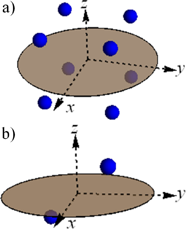
Figura 2 Different cases where inversion is present. a) Inversion is composed by three perpendicular mirror planes, each one exist by itself. b) There is inversion but not the independent mirror planes.
In the next section we will discuss the way in which all these matrices are related to each other and with the nonzero coefficients in the susceptibility for a particular crystal or structure.
3. Fundamentals of group theory
Group theory is a branch of mathematics, it is a general theory that can be applied to many situations, physics and other fields of mathematics. In essence, there are three necessary properties that must be fulfilled by a set of matrices to form a group under a particular operation, in this case the usual product of matrices. Therefore, the product of any two elements of the group generates also an element of the same group. The identity element (E) is always in the group as well as the inverse element or the reciprocal element for each element of the group is also in the group. For example, if a matrix A is inside a group, must be also inside this group its inverse element denoted by A-1 in such a way that A · A-1 =E
Now we are going to discuss two particular examples of a rotation group: C2 and C3υ . In the first case, the explicit matrix is given by
this is a rotation of 180° around the z-axis. Thus, the product of this element by itself generates

A more complicated example is the group C3υ , here the rotations are done by 120° and also there is an additional element, there are mirror planes. Mirror planes are labeled here with a sigma σi (i = 1, 2, 3), which means that a reflection around the dotted lines generates exactly the same object (See Fig. 4). These mirror planes are planes perpendicular to the plane of the figure and actually can be imagined as a two-dimensional object in a plane.

In a similar way, if we take three times C3, the result is the object in the original position as can be seen in Fig. 4. Mathematically this is
We are not going to discuss further higher groups of symmetry but we are going to show how this is related to the calculation of the susceptibility tensors that describe the atomic crystals response in nonlinear optics interactions. Therefore, the next section is devoted to this topic.
4. Neumann’s principle and second rank tensor transformation
The relation between the matrices and the nonzero elements in the susceptibility tensors is given via the Neumann’s principle 2:
“The symmetry elements of any physical property of a crystal must include the symmetry elements of the point group of the crystal.”
This means that, after applying a symmetry operation belonging to a particular crystal, a particular property of this should remain the same, for instance the tensorial elements of the susceptibility (which is a physical property) must fulfill this condition. In our case, depending on the crystal we can apply the rotations or mirror planes or other symmetry operation belonging to the point group of the crystal to the susceptibility tensor and after these transformations, Neumann’s principle implies that it must remain the same.
Let’s start with a third-rank tensor χ'lmn , which is nothing else that a set of numbers (coefficients) provided on a given coordinate system. When we now apply a symmetry operation to the crystal, mathematically this is described as a linear transform through the relation,
which mixes the original coefficients. In general, this is the way for transforming a third-rank tensor. Here Rab is a matrix and the subscripts i, j and k are running from 1 to 3 in stance of the x, y and z coordinates. However, physics/Neumann’s principle then requires:
and now Rab is a particular symmetry operation matrix in the group and the tensor after the transformation must be the same tensor which is going to be transformed, this is χijk = χlmn .This procedure generates a system of equations which must be solved in order to get the nonzero elements in the susceptibility tensor and also as there are more equations than variables, consistency must be checked.
A general third rank tensor can be represented as 4
where dijk can be understood in the following way. First index “i” is related to the external column vector and determines a row in it, second index “j” and the third one “k” are associated with the columns and rows in the internal 3 x 3 matrices.
Now, we can calculate the resulting susceptibility tensor for a crystal with group of symmetry C2. To avoid extra complications and keep this as clear as possible, we are going to take only a two-dimensional crystal or this could be thought only as the surface of the crystal. For doing this we need to specify a system of coordinates, in particular a possibility is shown in Fig. 5, where to the left an example of a crystal with C2 symmetry is shown and to the right there is a possible unit cell with a fixed system of coordinates is displayed.
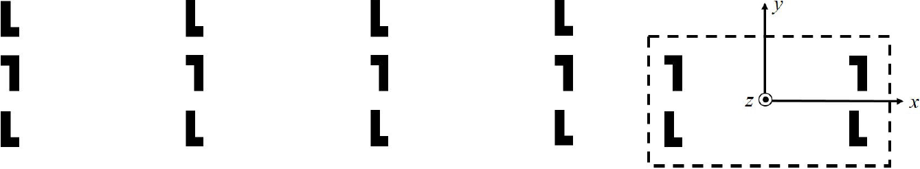
Figure 5 Right, a two-dimensional crystal with C2 symmetry. Left, a possible unit cell with a particular system of reference.
Therefore, to calculate the susceptibility third-rank tensor for a crystal with C2 symmetry, Eq. (9) is applied, where Rab is now the matrix given in Eq. (5) and the third-rank tensor is given by Eq. (10). Thus, after contracting the matrices with the tensor to the right side of the Eq. (9) gives
this system of equations shown above is very easy but in general could be more complicated. It is straightforward to think that for an element to be the same as its negative implies that it must be zero. Therefore after solving it the final tensor is
which, as mentioned before, it is the susceptibility third-rank tensor for a crystal with C2 symmetry and the subscript z means that the z direction is used as the twofold rotation axis. However, this form of tensor is different when compared with the one given in general group theory literature, e.g. Powell’s book 4, which is reproduced below:
Clearly, this tensor is totally different to the one shown in Eq. (12) but for the number of nonzero tensorial elements. Additionally, Powell assumes symmetry along the tensor diagonal. The difference between both tensors has its origin in the different system of reference chosen to calculate the nonzero elements according to the symmetry of the crystal in that system. In our case, the symmetry group is the same as in Powell’s but the latter uses a rotation about the y-axis. Hence, the matrix of rotation used by Powell is the following
After using this matrix with Eq. (9), yields
which immediately leads to Eq. (13), reproduced again below:
where subscript y means that the y direction is used as the twofold rotation axis.
We now move our discussion around the C3υ symmetry group and explain how one can get both possibilities enlisted in the tables from classic books 1,2. Moreover, we will show how to obtain from one configuration the other one and a general disposition of the nonzero elements in the tensor.
In this case, the rotation matrix will be defined with the rotation axis around z-axis and from Eq. (5), we get
Now, we are going to consider the configuration given in Fig. 6, where an object with C3υ symmetry is sketched. Of course, there are also crystals with this symmetry but just for pedagogical illustration we are going to use this simple two-dimensional object.

Figure 6 Object with C3υ symmetry, in a fixed system of coordinates. συ is the principal mirror plane in x-axis.
In this case, there is a mirror plane over the x-axis, the matrix that described it is given by
The others mirror planes, labeled
which is a trivial system of equations with solution
and again, using Eq. (9) but now with the C3υ matrix given in Eq. (17) and this “intermediate” tensor, yields
The above system of equations is harder to solve than the one in Eq. (19), still it has a solution and it is consistent with all the equations (there are more equations that variables). When solved, the final tensor has the form:
Again, this tensor is different to the one given by Powell 4, which is reproduced below (please note that in the book of Powell, the coefficient “2” multiplying the elements X112 and X121 is wrong):
The discrepancy occurs because the system of reference used to derive the tensor has not been defined a priori. Here, in this paper, it is chosen the y-axis as a principal mirror plane, as illustrated in Fig. 7, where the matrix is given by

Figure 7 Object with C3υ symmetry, in a fixed system of coordinates. συ is the principal mirror plane in y-axis.
(As a side comment we mention that in solid state physics and especially X-ray diffraction each crystallographic group and its atoms are described in a given coordinate system, and afterwards the symmetry elements are deduced in this predefined coordinate system, see e.g. Ref. 5).
This time, using this matrix Eq. (24) and the rotationmatrix given in Eq. (17) as well as the procedure described above, together with Eq. (9), yields the correct tensor for the system of reference shown in Fig. 7:
The tensor given in Eq. (22) and the last one obtained in Eq. (25) are related and as mentioned before the position of the nonzero elements in the tensor is going to change in accordance with the system of reference used to derive the nonzero independent elements in the tensor in agreement with group theory. To show this, we are going to use Eq. (8) again and transform the tensor given by Eq. (22) to a general rotating frame using the matrix from Eq. (5). Thus, after contracting the tensor, yields
Here, it is clear that the number of nonzero elements is bigger than before but still the number of independent elements remains the same. Moreover, when ϕ = 0the original tensor is recovered [Eq. (22)] and for the case of ϕ = π/2 the tensor given in Eq. (25) will be obtained only changing d111 → d222. Therefore, somehow the tensor still has some “memory” of the fixed system of reference used to calculate the nonzero elements due to its intrinsic symmetry.
For additional examples and discussion regarding the interaction of these tensors with the electromagnetic fields, the interested reader can consult Refs. 6 and 7.
5. Conclusions
The number of nonzero elements in a tensor associate to the susceptibility in a crystal strongly depends on the original system of reference in which the symmetry elements were defined. However, even if the relative position of the nonzero tensor elements change, the number of independent elements remains the same under any transformation by a rotation matrix defined by an arbitrary angle ϕ.

