


![Synthesis and Characterization of Three New di-n-butyl [bis (alkyl-aminopropionic acid)]tin (IV)](/img/en/prev.gif)


 text new page (beta)
 English (pdf)
 Article in xml format
 Article references
 Send this article by e-mail
 Cited by SciELO
  Similars in
SciELO
Similars in
SciELO 
 Permalink
1. Introduction
Melamine (C3N6H6 MEL) is a triazine-based chemical intermediate that is commonly used in manufacturing amino resins, plastics and flame retardants. It is not approved for use as a feed or food additive. However, it has been added illegally into feedstuffs or food to artificially distort their crude protein content. It received considerable public attention after the pet food contamination scandal in North America in 2007 and the MEL-tainted-milk powder incident with an estimated 300,000 victims in China in 2008 [1]. To protect public health and food safety, many countries and groups have established the criteria of Maximum Residue Limits (MRLs) for MEL in various everyday products [2]. Therefore, there is an urgent need to establish a simple, effective and highly sensitive method for the analysis of trace MEL.
Researchers have been looking for good materials as gas sensors with high sensitivity for a long time [3-10]. Carbon nanotube (CNT) and graphene exhibit potential applications in this field because of their unique properties such as high surface to volume ratio [11-19]. After their successful fabrication [19, 20], experiments have shown that CNT and graphene can be good sensors for some gases with high sensitivity [21, 22]. Basically, it is expected that the adsorption of gas molecules on the sensors is stable and the changes of the conductivity should be observable [23-26]. Wang et al. have investigated MEL interaction with pristine and defected graphenes [27]. They found that silicon doping can improve the affinity of graphene with MEL.
Carbon nitrides are promising candidates to complement carbon in materials' applications. However, at ambient conditions, graphitic C3N4 (g-C3N4) is regarded to be the most stable allotrope. Carbon nitride can exist in various phases not only depending on C to N ratio, but also on atomic arrangements [28]. A very careful discussion of the history of chemical approaches toward diverse C3N4 derivatives was recently given by Kroke and Schwarz [28] and Fuess et al.[29]. A polymeric derivative was made by Berzelius and named by Liebig in 1834 as ''melon'' and is regarded as one of the oldest synthetic polymers as such [30]. After 170 years, the diverse syntheses of g-C3N4-like materials cover a broad set of diverse carbon- and nitrogen-rich starting compounds. For example, Kouvetakis et al. decomposed derivatized MEL precursors at 400-500 °C and obtained an amorphous carbon nitride with the correct composition and a broad graphitic stacking peak [31]. Carbon nitride has attracted considerable interest and has been widely used in electronic devices, thermoluminescence dosimeters, humidity sensors, coatings, and catalysts because of its interesting electronic, chemical, mechanical, and tribological properties [32]. Because the main reagent for synthesis of carbon nitride-based materials is MEL, we think that carbon nitride can be an interesting choice for MEL adsorption. Recently, mesoporous carbon nitride, hollow carbon nitride spheres, carbon nitride nanotubes (CNNT), and carbon nitride films were successfully synthesized using various molecular precursors and synthetic processes [33].
Molecular interaction (e.g. of H2, NH3, H2CO and so forth) with the CNNT surface is a subfield of considerable interest because of potential applications such as surface modification, fuel cell, gas sensor and hydrogen storage [34-36] (35). In this work, the interaction of single and multiple MEL(s) with CNNTs will be theoretically investigated based on analysis of structure, energies, electronic properties, etc. The main purpose of this study is to gain fundamental insights into the influence of adsorbed molecules on the electronic properties of the nanotube, and how these effects could be used to design more sensitive gas sensing devices.
2. Computational details
We selected a (9, 0) zigzag CNNT, consisting of 108 C and 108 N atoms, in which the end atoms were saturated with hydrogen atoms to reduce the boundary effects. Geometry optimizations, energy calculations, and density of states (DOS) analysis were performed on a CNNT and different n MEL/CNNT complexes using with the B3LYP functional [37, 38] augmented with an empirical dispersion term [39] (B3LYP-D) with 6-31G basis set including the d-polarization function (denoted as 6-31G (d)) as implemented in the GAMESS suite of program [40]. Gauss-Sum program was used to obtain the density of state (DOS) plots [41]. The B3LYP has been demonstrated to be a reliable and commonly used functional in the study of different nanostructures [42-49]. We have defined adsorption energy in the usual way as:
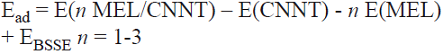 (1)
(1)
where E(n MEL/CNNT) corresponds to the energy of the CNNT, in which the single or multiple MEL has been adsorbed on the inner and outer wall, E(CNNT) is the energy of the isolated tube, E(MEL) is the energy of a single MEL molecule, and EBSSE is the energy of the basis set superposition error. The negative value of Ead indicates that the adsorption is exothermic. The canonical assumption for Fermi level (EF) is that in a molecule (at T = 0 K) it lies approximately in the middle of the highest occupied molecular orbital (HOMO) and the lowest unoccupied molecular orbital (LUMO) energy gap (Eg). It is noteworthy to mention that, in fact, what lies in the middle of the Eg is the chemical potential, and since the chemical potential of a free gas of electrons is equal to its Fermi level as traditionally defined, herein, the Fermi level of the considered systems is at the center of the Eg.
3. Results and discussion
3.1. Structural analysis
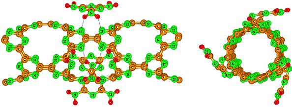
In Fig. 1, we display the top and side views of the optimized structure of (9, 0) zigzag CNNT. The CNNT converges to unsmooth tubular surface because of the N-N lone pair repulsions and the porous structure. All of the bonds (C-N and C-C) are vertical (V) or diagonal (D) to the tube axis. There are three types of C-N bonds and two types of C-C bonds in the structure of CNNT. The DC_N bonds are in two different environments as shown in Fig.1, including the bonds near to DC_C and VC_C with equilibrium lengths of 1.33 and 1.34 Â, respectively. The length of both DC-C and VC-C bonds is about 1.51 Â, which is in good agreement with the previous findings [50]. Since the CNNT has a highly porous structure, it is expected that the target molecule diffuses into the hollow area at its center.

3.2. The MEL adsorption on the CNNT
In order to obtain stable configurations of a single MEL adsorbed on the surface of the CNNT, various possible initial adsorption geometries are considered, including single (nitrogen, carbon or hydrogen), double (N-H or C-N) and triple H-N-H bonded atoms close to C and N atoms in the exterior of the tube. Full structural relaxation, without any constrain, was performed on each initial configuration. However, only one local minimum structure was obtained after the relaxation process (Fig. 2). In this configuration, MEL molecule locates on the top of the porous site of tube, so that one of the −NH2 group is close to N atoms of the CNNT. Therefore, two new H-bonds were formed between H atoms of the MEL and N atoms of the nanotube with length of 2.42 Â. More detailed information from the simulation of the MEL/CNNT systems, including values of E ad and electronic properties is listed in Table 1. As can be seen in Fig. 3, the calculated molecular electrostatic plots of MEL and CNNT can explain the exothermic nature of this adsorption (Ead = -21.9 kcal/mol). Partial negative charge (red color) on the N atoms of CNNT that is focused in porous sites makes them reactive toward the hydrogen atoms of MEL (as Lewis acid sites) with partial positive charge. It is worth saying that other initial configurations re-oriented to this stable configuration.
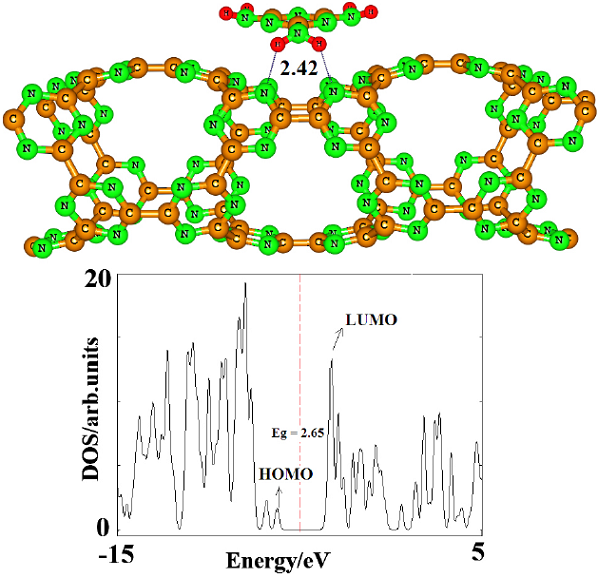
Fig. 2 Partial structure of optimized MEL/ CNNT complex and its density of states (DOSs) plot. Bonds are in Â. Dash line is Fermi level. The DOS plot shows that the Eg of the tube is significantly decreased after the MEP adsorption.
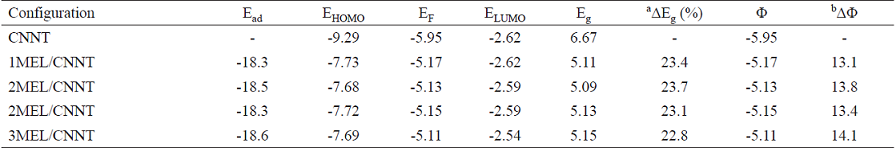
Table 1 Adsorption energy (Ead kcal/mol) HOMO energies (EHOMO), LUMO energies (ELUMO) and HOMO-LUMO energy gap (Eg), work function (Φ) and Fermi level energy (EF) of systems in eV at B3LYP-D/6-31G (d) level of theory.
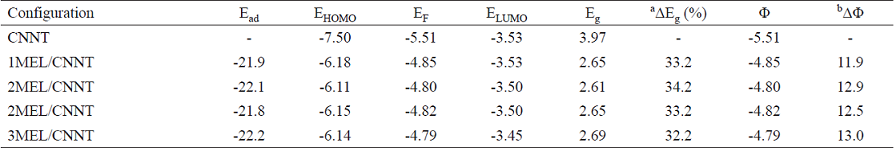
a Change of Eg of tube after MEL adsorption.
b The change of work function of the tube after the MEL adsorption
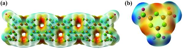
Fig. 3 The calculated molecular electrostatic potential surface (MEP) of the (a) CNNT and (b) MEL. The surfaces are defined by the 0.0004 electrons/ b3 contour of the electronic density. Color ranges, in a.u.: blue, more positive than 0.010; green, between 0.010 and 0; yellow, between 0 and -0.010; red, more negative than -0.010.
3.3. Co-adsorption of MEL atoms
With each porous site in the structure of CNNT being a potential adsorption site, the possibility of co-adsorption of MEL was explored. As shown in Fig. 4, two initial models are considered when the second MEL molecule is adsorbed on the CNNT. Each structure is fully relaxed. The most stable configuration (labeled as A) is that in which two MEL molecules are located on the top of two porous sites of the tube far from each other on the opposite sides of the circumference (Fig. 4A). The Ead of this configuration is about -22.1 kcal/mol per MEL molecule, which is slightly higher than that of the most stable configuration of the adsorption of one MEL molecule. Additionally, another metastable adsorption configuration is obtained as shown in Fig. 4B. In the metastable configuration (labeled as B), the second MEL molecule is adsorbed on one of the porous sites which is different from the first site. The Ead of the metastable configuration is -21.8 kcal/mol (Table 1). Next, three MELs are placed on the top of the porous sites (Fig. 5). The Ead of this process is found to be about -22.2 kcal/mol per MEL, which is slightly higher than that of one or two MEL(s) adsorption. The tube diameter is increased from 7.24 to 7.41 Â when three MEL molecules are bonded to its surface.

3.4. The electronic properties
The fundamental sensing mechanism for these devices is the modulation of their conductivity as a result of the charge transfer between them and adsorbates. In the following, the influence of the MEL adsorption on the electronic properties of the CNNT was studied. As shown by the calculated DOS in Fig. 1, the pristine tube is found to be a semiconductor with a wide Eg of 3.97 eV. By referring to Fig. 1, it can be seen that in MEL/ CNNT complex conduction level remains constant, while valence level shifts from -7.50 to -6.18 eV so that the Eg value significantly reduced to 2.65 eV. It is well known that the Eg (or band gap in bulk materials) is a major factor in determining the electrical conductivity of a material and there is a classic relation between them as follows [51]:
 (2)
(2)
where σ is the electrical conductivity, k is the Boltzmann's constant and A (electrons/m3K3/2) is a proper constant. Peyghan et al. [51] have shown that Eq. 2 is compatible with the experimental results, and the electrical conductivity increases by decreasing the Eg, and vice versa. Therefore, the considerable change of about 33.2% (Table 1) in the Eg value of MEL/CNNT demonstrates the high sensitivity of the electronic properties of pristine CNNT to the presence of MEL molecule. Therefore, the presences of the MEL molecules can be detected by calculating the conductivity change of CNNT before and after the adsorption process.
To further investigation of the sensitivity of pristine CNNT, we have studied the changes of work function of systems ascribed to the charge transfer between MEL and the adsorbents. The work function of a semiconductor is the least amount of energy required to remove an electron from the Fermi level to a point far enough not to feel any influence from the material. The change of work function of an adsorbent after the gas adsorption alters its field emission properties. The readout of gas-induced work function changes via suspended gate field effect devices and has been accepted as a promising technique for the realization of a sensor platform for several years [52]. However, the emitted electron current densities in vacuum are theoretically described by the following classical equation:
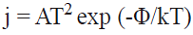 (3)
(3)
where A is called the Richardson constant (A/m2), T is the temperature (K) and Φ (eV) is the material's work function. Work function values were calculated using Φ = Einf - EF. Where Einf is the electrostatic potential at infinity and EF is the Fermi level energy. In this consideration, the electrostatic potential at infinity is assumed to be zero. The work function changes (∆Φ) were calculated by subtracting the work function of the clean tube from that of the corresponding adsorbed system. The results of Table 1 reveal that calculated work function of the pristine CNNT is about 5.51 eV. After the adsorption of one, two and three MELs on the tube, work function of CNNT is considerably decreased to 4.85, 4.80 and 4.79 eV, respectively. However, as can be seen from Eq. 3, the emitted electron current density is exponentially related to the negative value of Φ. Therefore, the emitted electron current density from the CNNT will be significantly increased after the MEL adsorption.
3.4. The effect of nanotube length
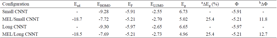
Subsequently, we investigated the potential effect of the tube length on the Ead and electronic properties of the nanotube. To this end, two CNNTs were selected with the optimized length of about 21.6 and 45.6 Â, being 12.0 Â smaller and longer that the former studied tube, respectively. The smaller CNNT has 72 C and 72 N atoms, while the longer one has 144 C and 144 N atoms in which the end atoms were saturated with hydrogen atoms (Fig. 6). The data of Table 2 and DOS spectrum in Fig. 4 indicate that HOMO, LUMO, Eg, Fermi level energies and the work function of these tubes are nearly equal to those of the first studied tube. The Ead of one MEL and the change of Eg are calculated to be the same as those on the former tube. Therefore, one can conclude that the effects of increasing the length of the tube may be negligible on the adsorption process and the electronic properties of the tube.

Fig. 6 Optimized structure of (9,0) CNNT with (a) length of 21.6 Å, (b) length of 45.6 Å and their density of states (DOSs) plot. Dash line is Fermi level. The DOS plots indicate that increasing the length of the tube the Eg is slightly decreased.
Table 2 Adsorption energy (Ead, kcal/mol) HOMO energies (EHOMO), LUMO energies (ELUMO) and HOMO-LUMO energy gap (Eg), work function (Φ) and Fermi level energy (EF) of systems in eV at B3LYP-D/6-31G (d) level of theory.
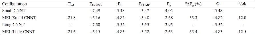
a Change of Eg of tube after MEL adsorption.
b The change of work function of the tube after the MEL adsorption
3.5. Effect of density functionals
Finally, we investigated the influence of DFT functionals on the obtained results. To this aim, we repeated the calculations at M06-2X/6-31G (d) method [53] and summarized the results in Tables 3 and 4. The results obtained by this method indicate that structural and energetic results are in good agreement with those obtained by B3LYP, while the calculated electronic properties of the HOMO, LUMO, EF, and Eg depend almost on the kind of functional. The M06-2X values of Eg are larger than those of the B3LYP. However, both of the functionals show the significant change of Eg for the CNNT during the MEL adsorption. We think that the proposed sensor may have some advantages, including high sensitivity: the Eg of CNNT is appreciably sensitive to the presence of MEL so that it decreases by about 33.2% (at B3LYP level of theory) or 23.4% (at M06-2X level of theory) after the adsorption of MEL, pristine application: this CNNT can monitor the MEL molecule in its pristine type without manipulating its structure through doping, chemical functionalization, making defect, etc., short recovery time: the adsorption energy of MEL molecule is not so large to hinder the recovery of CNNT and, therefore, the sensor will possess shorter recovery time.
Table 3 Adsorption energy (Ead kcal/mol) HOMO energies (EHOMO), LUMO energies (ELUMO) and HOMO-LUMO energy gap (Eg), work function (Φ) and Fermi level energy (EF) of systems in eV at M06-2X/6-31G (d) level of theory.
a Change of Eg of tube after MEL adsorption.
b The change of work function of the tube after the MEL adsorption
Table 4 Adsorption energy (Ead kcal/mol) HOMO energies (EHOMO), LUMO energies (ELUMO) and HOMO-LUMO energy gap (Eg), work function (Φ) and Fermi level energy (EF) of systems in eV at M06-2X/6-31G (d) level of theory.
a Change of Eg of tube after MEL adsorption.
b The change of work function of the tube after the MEL adsorption.
4. Conclusion
A MEL molecule adsorption on the CNNTs is investigated using DFT calculations in terms of Ead, Eg changes, work function, structural deformation, etc. The adsorption is site-selective, so that the MEL prefers to be adsorbed on the top of the porous site of the nanotube. We found that by increasing the coverage of adsorbed MEL molecules, the Ead per molecule is slightly increased. The results reveal that the Eg of CNNT is very sensitive to the presence of MEL molecules as its value reduces from 3.97 eV in the pure tube to 2.65 eV in the stable configuration of MEL/CNNT complex. This phenomenon dramatically increases the electrical conductivity of the nanotube, suggesting that the CNNT can be a potential sensor for MEL molecule detection.

