


Services on Demand
Journal
Article
 English (pdf)
 Article in xml format
 Article references
 Send this article by e-mail
Indicators
-
 Cited by SciELO
 -
 Access statistics
Related links
-
 Similars in
SciELO
Similars in
SciELO
Share

 Permalink
Journal of the Mexican Chemical Society
Print version ISSN 1870-249X
J. Mex. Chem. Soc vol.58 n.4 Ciudad de México Oct./Dec. 2014
Article
Rare Earth Conversion Coatings Grown on AA6061 Aluminum Alloys. Corrosion Studies
Silvia Beatriz Brachetti-Sibaja,1 Miguel Antonio Domínguez-Crespo,2* Aidé Minerva Torres-Huerta,2 Edgar Onofre-Bustamante,2 and Wencel De La Cruz-Hernández3
1 Instituto Tecnológico de Ciudad Madero (ITCM), Av. 1º de Mayo s/n, Col. 1º de Mayo. Cd. Madero 89650 Tamps. México.
2 Instituto Politécnico Nacional, CICATA-Altamira km 14.5, Carretera Tampico-Puerto Industrial Altamira. Altamira 89600 Tamps. México. mdominguezc@ipn.mx.
3 Centro de Nanociencias y Nanotecnología, Universidad Nacional Autónoma de México, A. P. 2681, Ensenada 22800 B.C., México.
Received September 27th, 2013
Accepted June 10th, 2014.
Abstract
The present work is aimed to investigate the corrosion resistance of rare earth (RE) protective coatings deposited by spontaneous deposition on AA6061 aluminum alloy substrates. Coatings were deposited from water-based Ce(NO3)3 and La(NO3)3 solutions by varying parameters such as rare earth solution concentration, bath temperature and immersion time. The values of the Tafel slopes indicate that the cathodic process is favored by concentration polarization rather than activation polarization.
Keywords: Aluminum alloy, Chemical conversion coatings, Rare earth elements, Corrosion evaluation, Cerium oxide, Lanthanum oxide.
Resumen
Este trabajo tiene como objetivo la investigación de la resistencia a la corrosión de recubrimientos de tierras raras mediante el proceso de inmersión, depositadas en aleaciones comerciales de aluminio AA6061. Para ello, se utilizaron diferentes soluciones de Ce(NO3)3 y La(NO3)3 evaluando parámetros tales como: la concentración de la solución, temperatura y tiempo de inmersión. Los valores de las pendientes de Tafel y su comportamiento indican que el proceso catódico está favorecido por una polarización por concentración más que la polarización por activación.
Palabras clave: Aluminio, Tratamientos de conversión química, Tierras raras, Corrosión, Óxido de cerio, Óxido de lantano.
Introduction
Aluminum and its alloys are widely used in engineering applications such as aeronautics and construction due to their low density, favorable mechanical properties, and relatively good corrosion resistance. Aluminum alloys are very reactive materials capable of forming in moist air a robust, protective thin film of aluminum oxide to minimize extensive corrosion. However, this native oxide layer remains vulnerable under conditions different from its isoelectric point, where the metal ion or its oxo-anions are soluble, leaving bare aluminum exposed to acidic and extreme basic pH, which regularly provokes localized corrosion [1-10].
These kinds of alloys are used in a wide variety of fields such as the automobile, aeronautical, aerospace, and electronic industries, among others. In these industries, the use of pretreatments prior to painting or adhesive bonding is an essential technology to prevent local corrosion [1-10]. Each pretreatment type produces a surface coating that not only provides a first defense against corrosion, but also provides adhesion that is needed for primer and top coating performance; i.e., pretreated coatings can be used alone or in conjunction with over-coatings (organic primers and top coatings), which add physical durability and generally improved corrosion protection. Then, conversion coatings serve to structurally and chemically stabilize and control the interfacial properties of the aluminum substrate to allow a predictable, stable performance of the coated system [11]. In this way, several studies have been focused on the use of rare earth (RE), or lanthanide compounds as a green alternative for substituting the commonly used chromate conversion coatings, not only because of their effectiveness but also due to their low toxicity compared to chromates [12-18]. Lanthanide elements are characterized by large atomic radii, stable electronic configurations, multiple oxidation states, typically +3 and +4 and occasionally +2, reactivity with water to form a neutral oxide; formation of stable, insoluble oxides of mixed valence states; complex coordination chemistry; instability of lower valence salts in alkaline conditions with a tendency to hydrolyze and precipitate as the hydrated oxide; and an extremely low reduction potential [19-21]. The chemical properties of rare earth conversion coatings (RECCs) function mainly as barrier coatings suppressing the cathodic half-reaction. In comparison with chromate treatments, RE elements form durable aluminum alloy surface conversions but do not passivate anodic corrosion reactions. Therefore, improvements in transport control, electrochemistry, and solubility of the species involved in corrosion inhibition are required to attain the performance of chromate conversion coatings [1, 2, 22, 23].
Among the lanthanide compounds, lanthanum, cerium, praseodymium, and ytterbium have often been examined as the most prevalent and inexpensive of the rare earth metals, and of these, cerium and lanthanum salts have been used successfully as corrosion inhibitors on different metals and aluminum alloys.
RE conversion coatings can be applied by different methods, which include immersion, spraying, brushing, swabbing, and electrolytic [24-29]. The solutions used in the deposition of rare earth conversion coatings generally contain a cerium or lanthanum salt such as cerium or lanthanum nitrate, where the deposition mechanism for these coatings involves both the oxidation of aluminum and formation of hydroxyl ions:

It is clear that the corrosion process can depend completely or partially on the rare earth protective properties and/or the diffusion pathway through these layers and not only on the species that are reduced cathodically but also on the metallic ions resulting from the anodic process. Therefore, detailed information on electrochemical behavior is required for inhibiting dissolution reactions.
The aim of this work is to study in detail the electrochemical properties of RE conversion coatings formed on AA6061 aluminum alloys from a wide variety of bath conditions to determine the optimal conditions required for achieving maximum protection. Specifically, the corrosion resistance in 3.5 wt% NaCl corrosion medium is investigated by Tafel and electrochemical impedance spectroscopy (EIS) measurements. The X-ray photoelectron spectra (XPS) have been used to determine the nature and content of corrosion compounds.
Results and Discussions
Electrochemical Measurements
Tafel plots
As it was mentioned previously, the influence of the electrolyte composition, immersion time, and temperature on the electrochemical behavior of coated aluminum was investigated. Tafel measurements were performed from the hydrogen evolution region to the anodic side at a sweep rate of 1 mV s-1. By taking into account that a reasonable criterion for steady state would be a change of less than 5 mV in Ecorr, all the corresponding measured values were obtained after 20 min, when steady state had been reached. From the overall trials, only the most outstanding electrochemical results are shown and compared for each rare earth concentration.
Figures 1 and 2 show selected Tafel curves of the cerium and lanthanum conversion coatings formed on AA-6061 aluminum alloy substrates under different experimental conditions, respectively. From these plots, the corresponding Tafel slopes ba and bc, for the partial anodic and cathodic processes, as well as current density (icorr) and corrosion potential (Ecorr) were obtained by using the numerical calculation program contained in Gamry ZRA Reference 600 potentiostat/galvanostat. The intersections of Tafel straight lines were found to be very close to the corresponding rest potentials (see Table 1).
In general, for CeCCs, it is apparent that the electrochemical performances provided by the conversion layers are clearly affected by the experimental conditions. The curves and data reveal a dependence on the Ce ion concentration. The samples treated with low Ce(NO3)3 concentrations (0.01-0.1 g L-1) shifted from 100 mV to more noble potentials (Figure 1a-b). Under these conditions, RECCs ennobled the corrosion potential, reducing the thermodynamic tendency to corrosion, whereas the opposite effect (reducing up to 350 mV) is observed with Ce ion concentrations of 0.5-1.0 g L-1 (Figure 1 c-d).
The corrosion current density obtained from the samples treated with 0.01gL-1 of cerium salts at 50, 70, and 90 °C (Figure 1a) exhibits a drop of about one order of magnitude (24.54 ± 1.76, 38.90 ± 2.84, 10.71 ± 0.53 mA cm-2, respectively) in comparison with bare aluminum (125.89 ± 6.93 mA cm-2). It is also observed that the corrosion potential (Ecorr) displays small variations without a clear trend -502 ± 10, -516 ± 20, -462 ± 16 mV in comparison with -508 ± 22 mV of the uncoated samples. Using bath temperatures of 70 °C and higher, a passivity region begins to appear, however, at 70 °C the passivity domain is unsteady and the oxide film fails after 180 mV. At 90 °C and 600 min, the pitting resistance is improved by increasing a perfect passivity domain. Nevertheless, the morphology under these conditions reveals the presence of cracks or pores [30, 31], which could affect the performance of the conversion layer for industrial applications, allowing the electrolyte access to the substrate and hence the beginning of the corrosion process.
As the Ce concentration was increased to 0.1 g L-1 (Figure 1b), the corrosion potential was shifted about 100 mV in the positive direction for the optimal case (90 °C); in comparison with a bath concentration of 0.01 g L-1 of Ce, it reduced the corrosion current density from 10.71 ± 0.53 to 1.14 ± 0.58 mA cm-2. This behavior is attenuated as a function of bath temperature. A similar performance was observed previously by Heller and coworkers [32], who demonstrated that treated samples with longer immersion times or higher temperatures reduced the density and size of cracks, resulting in less damage and electrochemical properties that were better than those displayed by coatings subjected to shorter immersion times and/or lower temperatures during the chemical conversion processing. The curves also indicate that the passivation of the aluminum alloy is more efficient at higher temperatures, improving the pitting resistance by increasing the passivity domain.
In contrast, the Tafel plots corresponding to the as-prepared samples, using bath concentrations of 0.5 and 1 g L-1, different immersion times, and different temperatures, display, in general, poor or unacceptable properties against corrosion (Figure 1c-d). In these cases, the Ecorr was shifted between 100 ± 13 mV and 480 ± 25 mV towards the cathodic direction, whereas icorr was slightly increased in comparison with bare aluminum (Table 1). Specifically, coated specimens using 1 g L-1 at 70 °C and 600 min of immersion time show a slight enhancement in the corrosion properties with a considerable negative shift in the Ecorr, (480 ± 25 mV) and a decrease in the icorr of 13.48 ± 0.40 mA cm-2 in comparison with the values obtained for bare aluminum. The increasing corrosion current density with increasing bath concentration suggests that the surface of these films, grown on the AA6061 aluminum alloy, is more susceptible to chloride attack and metallic dissolution, i.e. the alteration in the corrosion potential has been attributed to the cracked coarse films and their behavior in chloride medium. From the range of evaluated experimental conditions, the Tafel plots regarding the cerium conversion coatings (CeCCs) indicate that films formed at 0.1 g L-1 and 70 °C have the lowest corrosion current density (icorr) at 1.14 ± 0.58 mA cm-2 and highest corrosion potential at -360 ± 10 mV, while specimens grown with a cerium ion concentration of 0.5 g L-1 and 90 °C for 600 min, have one of the lowest Ecorr, -609 ± 23 mV, and one of the highest icorr at 457 ± 19.93 mA cm-2.
Usually, it is expected that cerium based conversion coatings ennoble the corrosion potential, reducing the thermodynamic corrosion tendency, and as a consequence, restraining the molecular oxygen reduction reaction. Nevertheless, the ennoblement of Ecorr for the treated samples was lost for cerium bath concentrations above 0.5 g L-1. In this way, the positive values of Ecorr, in comparison with bare aluminum, have been correlated with the characteristics of oxide/hydroxide protective films. On the other hand, the corrosion potential moved towards the negative direction could be related to deep cracks produced during the thickening of the conversion films, which were probably extended into the substrate, provoking adhesion loss on the coating/metal interface. Thus, the Tafel plots indicate that the corrosion resistance imparted by cerium treatment depends upon the bath conditions.
It is also clear that the anodic-cathodic branches are modified by the presence of conversion coatings [33, 34]. The general behavior in the cathodic branch of coated samples is shown as a rectification of the shape and decrease in the cathodic currents [6] (a blocked anodic but not a cathodic electron transfer). At the opposite branch, + 250 mV, the anodic current density is low at increased temperature and potential independent, indicating the formation of an oxide/hydroxide layer on the electrode surface. These results also highlight the importance of selecting the proper deposition conditions for reaching a maximum in pitting corrosion protection, which in turn influences the corrosion rate of the electrode process. Then, the anodic branch was modified in the passive region, affecting the pitting potential values as a function of bath conditions, which is consistent with morphological features of the surfaces for each experimental condition, and possibly related to the uniformity of the deposited protective layer. The formation of superficial oxide/hydroxide compounds may be easily explained as follows: the CeCC deposition process is driven by the natural electrochemical potential differences between the aluminum matrix and intermetallic inclusions, then, the CeCC film growth is partially or totally hindered by intermetallic particles on the AA6061 aluminum alloy surface, which lowers the local pH, thereby favoring hydrogen evolution and oxygen reduction to OH-, which induces the precipitation of more stable compounds as hydrated cerium oxide [35-40]. In this context, the high Tafel slope reflects the leakage of water through the oxide.
The increase in OH- concentration as a result of the balance between formation and diffusion away from the electrode is too small to produce significant hydration of the oxide layer. Furthermore, another possibility to be considered is that the presence of alumina on the metallic surface markedly influences the hydrogen reduction process on the surface by reducing the value of its exchange current density ( io ) and increasing the Tafel slope, or by both [41, 42], which may also contribute to the observed differences in the Tafel slopes. The slopes in the range of ~120 mV dec-1 are correlated with the usual mechanism of hydrogen evolution by the Volmer reaction as the rds. Finally, it is important to note that the Tafel plots were carried out without stirring, but were repeated carefully to discard any transport phenomenon from the passivation effect.
In the case of lanthanum conversion coatings (LaCCs), no clear trend in the corrosion potential or corrosion current density is apparent for coated specimens (Figure 2 a-d), but the anodic and cathodic branches of the curves related to the corrosion resistance and hydrogen evolution reaction or oxygen reduction reaction are more affected by lanthanum ions than by Ce ions in the CeCCs. It can be seen in Figure 2, that the anodic branch of the aluminum/LaCCs system in 3.5 wt% NaCl tends to obey Tafel's Law, which suggests that the pitting potentials are increased and the metallic substrates are passivated, i.e., perhaps due to resistance to localized corrosion because the substrate is well-protected by its passivating film. The mechanism for this passivating films is based on the hydrolysis reactions experienced by La cations through the formation of complex hydroxylates, xM y + + yH2O → Mx(OH)x(xy-y) + yH+, which favor the formation of La(OH)3 or oxide precipitation. On the other hand, the cathodic polarization curves display a limiting diffusion current (iL) due to the reduction of oxygen or hydrogen evolution or both. Thus, the cathodic process is controlled by concentration polarization rather than activation polarization. Nevertheless, both branches were extrapolated back to the corrosion potential and, when possible, the corrosion current density was obtained assuming for some conditions that at the open circuit potential, the net rate of metal dissolution is equal to the net rate of oxygen reduction/hydrogen evolution, iL. The result in those cases is icorr 3.46 ± 0.17 E-3, 218.77 ± 10.10, and 120.22 ± 6.20 mA cm-2 (Table 1), obtained for La ion concentrations of 0.01 g L-1, 50 and 90 °C, and 0.1 g L-1 at 50 °C, respectively.
Specifically, treated samples with low lanthanum ion concentration (0.01 g L-1) at 70 and 90 °C, display poor protective properties, icorr, 61.65 ± 3.10 mA cm-2 (Ecorr -452 ± 13 mV), 218.77 ± 10.10 mA cm-2 (Ecorr -573 ± 17 mV), respectively, in comparison with the electrochemical performance of bare aluminum 125.89 ± 6.93 mA cm-2 (Ecorr -508 ± 22 mV). The LaCCs on the metallic substrate at 50 °C display an important enhancement of the electrochemical, icorr = 3.46 ± 0.17 E-3 mA cm-2 and a shift of the Ecorr in the positive direction by about 70 mV in contrast with the reference. The conversion films obtained with 0.1 g L-1 of lanthanum ions (Figure 2b) illustrate an overall enhancement in barrier properties using bath temperatures above 70 °C, icorr 2.29 ± 0.15, 3.89 ± .22 mA cm-2, and Ecorr -336 ± 9, -473 ± 12 mV were obtained at 70 and 90°C, respectively. In contrast, coated specimens formed at 50 °C do not demonstrate protective properties with icorr at 120.22 ± 6.20 mA cm-2 and Ecorr at -578 ± 12 mV. When the bath concentration was increased to 0.5 g L-1, independent of the immersion time (see Figure 2c), the trend to enhance the protective properties shifts the corrosion potential from positive (-516 ± 16 mV) to negative values (-608 ± 626 mV) and reduces the corrosion current densities up to 5.08 ± 0.29E-3 mA cm-2 as the bath temperature is increased.
Finally, layered substrates using 1 g L-1 of La show significant negative changes under all the studied conditions in comparison with bare aluminum (Figure 2d). In fact, the icorr results obtained at 50 and 70 °C show icorr values up to three times greater (426.57 ± 19.34 mA cm-2) than those observed with uncoated specimens (125.89 ± 6.93 mA cm-2), indicating that under these conditions the blockage of the cathodic sites by the formation of a La-conversion coatings on the surface does not inhibit the diffusion of oxygen, thus increasing the overall corrosion rate. The variations in the corrosion potential and corrosion current densities are attributable to the coverage of the active area on the electrodes by the La conversion coating.
By comparing both RECCs, it is observed that with higher RE concentrations (1 g L-1) there is a noticeable increase in icorr of 223.87 ± 7.12 and 426.57 ± 19.34 mA cm-2, for CeCCs and LaCCs, respectively, relative to the bare aluminum alloy (125.89 ± 6.93). However, baths with RE concentrations of 0.01, 0.1, and even 0.5 g L-1 offer an effective protection of the metal substrate in NaCl solution (Table 1). Of direct relevance to this work is the low electrochemical performance obtained with higher cation concentrations, which can be explained as follows: the increasing RE concentrations caused an increase in the number of precipitates, which formed a homogeneous granular morphology of a more compact, uneven and thick precipitate; around these agglomerates, some deep cracks and pores may form, reaching the aluminum substrate(Figure 3 a-b), which may be due to the internal coating stress developed during film growth or to the formation of some unstable hydroxide compounds, as it is the case of hydrated cerium oxide or Ce(OH)4.

For industrial use, the effectiveness of a coating for corrosion stability is usually measured after a post-treatment and subsequent application of paint [1, 6, 10]. By contrast, the Tafel measurements reported here were carried out on treated samples without top-coat application; however, the results are comparable with those previously reported for commercial applications. In such a case, although our measurements indicate that the corrosion current was increased with rare earth ion concentrations higher than 0.1 g L-1, a number of processes are simultaneously occurring, including coating coverage, nucleation, and coating growth. In terms of morphology, the optimal coating conditions appear for RE ion concentrations in the low g L-1 range. For example, bath temperature and immersion time for concentrations between 0.01 and 0.1 g L-1 produce changes in morphology that represent important benefits in the reduction of the corrosion current density. In contrast, for higher RE concentrations, the total coverage and thickness are increased, but porosity, cracks, and weaker adhesion compromise the resistance against corrosion. In conclusion, with optimized experimental conditions, lanthanum baths are better than CeCCs in reducing corrosion current density by as much as 102.52 times.
EIS analysis
The corrosion resistance of the conversion coating in 3.5 wt% NaCl solution was also evaluated by EIS. Taking bare aluminum as a reference, in general, the RE films tend initially to increase the impedance values and thereafter, when some hydrated oxides are well formed, the value of Rp associated with the semicircles is increased. With regard to the importance of this effect, it was considered that 1200 min of exposure in NaCl solution are necessary to reach a steady state in the impedance values for RECCs. After this immersion time, EIS measurements were carried out. The use of EIS to investigate the corrosion behavior of coated metals is very common, and it has been extensively used to characterize Al surfaces coated with traditional chromate-based films [43-46]. EIS is a quantitative tool to assess the improvement of the corrosion protection afforded by coatings or conversion layers [47].
Figures 4 and 5 a-d show the selected Nyquist plot of EIS spectra for coated AA6061 aluminum alloy using RECCs with different temperatures, immersion times, and different bath concentrations. The Nyquist plots for the as-prepared specimens with a cerium concentration of 0.01g L-1 are shown in Figure 4a. For comparison, uncoated samples are also shown in the Nyquist plots. The bare aluminum samples display the typical two well-defined time constants, the first time constant (~5.6 kΩ cm2) may be associated with the natural passivating oxide film (high-frequency region), which is formed on the aluminum substrate, whereas the second time constant is associated with the charge transfer resistance (low-frequency region, ~13.5 kΩ cm2). On the other hand, with the cerium coatings (0.01 g L-1), only one time constant is seen, clearly located at the high or medium frequency region and verified in Bode diagrams (not shown here), from 105 to 102 Hz . For this Ce concentration, it is also clear that the protective properties of the coating are increased with the bath temperature. The very high impedance values at intermediate and high frequencies (~380 KΩ cm2) for as-prepared samples at 90 °C and 600 min of immersion indicate that the outer oxide layer is very well sealed in comparison with the values shown by its counterparts, 22.31 ± 1.12 E3 and 61.98 ± 3.72 E3 Ω cm2, for specimens formed at 50 ant 70 °C, respectively. The results suggest that the aluminum surface with chemical conversion coatings synthesized at 90 °C is entirely covered by the anodic film, whereas at 50 and 70 °C, cracked layers are not protective due to the high conductivity of the electrolytic solution within the pores.
Analogous behavior was observed for samples treated with 0.1 g L-1 (Figure 4b), although these samples at 50 and 70 °C display similar charge transfer resistance, 89.07 ± 4.94 E3, 115.7 ± 5.28 E3 Ω cm2, respectively. Only at 90 °C and 1800 min of immersion time, an important enhancement in corrosion properties is observed, 396.2 ± 16.78 E3 Ω cm2. The higher bath temperature probably accelerated ionic transport in the substrate to initiate film formation and to promote a thicker growth of the conversion film to encapsulate some defects present in the film, thereby increasing corrosion protection [48]. As the cerium concentration was increased to 0.5 and 1 g L-1 (Figures 4 c-d), the coating featured losses in an important property (105.47 times), in comparison with the best value at 0.1 g L-1 (396.2 ± 16.78 E3 Ω cm2). At these cerium ion concentrations, some discrepancies in comparison with Tafel measurements are detected. The differences observed between Tafel and EIS measurements are explained in terms of the measurement of resistance polarization by AC impedance spectroscopy, which is not affected by the conductivity of the electrolyte; i.e. both contributions can be easily separated by this technique, in contrast to DC methods [49]. By associating the different experimental conditions, it is evident that the response of the cerium conversion treatment using an AC technique inhibited the data corresponding to the passive film at such a point that the Rpf-CPEpf loop disappeared. Thus, the range of measured frequencies only contains the response in impedances associated with the protective properties of the layer.
Nyquist spectra for selected lanthanum-based conversion coatings (LaCCs) are shown in Figures 5 a-d. Figures 5a-b present the results of the conversion films obtained for lanthanum concentrations of 0.01 and 0.1 g L-1, where it is seen that the higher enhancement in the coating resistance is achieved when the aluminum substrates are immersed for 600 min at 70 °C with values of about 125 and 650 KΩ cm2 for 0.01 and 0.1 g L-1. Under these conditions, the impedance data are mainly capacitive, suggesting that the surface of LaCCs remain passive during the immersion in NaCl solution. The performance is obtained as a result of a compact morphology without visible fissures, formed during the growth of the film (Figure 6 a-b).

On the other hand, the samples using 0.5 g L-1 at different temperatures and immersion times display very variable impedance values from 12.92 ± 0.28E3 to 233.7 ± 13.38E3 Ω cm2 (Figure 5c). Such variation in the electrochemical data can be explained in terms of the SEM measurements, where it was found that higher lanthanum ion concentrations lead to the formation of large clusters of oxides/hydroxides with two different morphologies, large irregular agglomerate islands and small semi-spherical grains with a columnar structure, both of which cause cracks or porosity during the film growth. In the first instance, these defects do not extend to the substrate, but during the EIS evaluation can affect the charge transfer resistance (Figure 7 a-b). In addition to the factors that affect the formation of fissures, pores or weakly adhered films during coating formation, the stress that induces these cracks can be also generated by two sources; the first one, during the deposition process itself (rapid quenching, solidification, thermal contraction, constraint due to underlying material, and stress relief due to micro-cracking), whereas a second one can result from a mismatch between the coefficients of thermal expansion of the ceramic layer (α = 10.6 E-6 and 11.9 E-6, K-1, for CeO2 and La2O3, respectively) and aluminum substrate (α = 7.1-8.3 E-6 K-1 and 23.4 E-6 K-1 for Al2O3 and metallic Al, respectively).

Particularly, the impedance response of LaCCs obtained at 50 °C is less effective and, in some frequency regions, similar to that displayed by CeCCs or even bare aluminum. At this temperature, a second semicircle begins to appear at low frequency regions, which may be due to the seepage of the electrolyte into the passivating film; i.e. apparently, the aluminum substrate is exposed to the corrosive solution through fine cracks or pores that run through the conversion layer, which become sealed on the surface at the bath temperatures of 70 or 90°C, which is not a robust condition to protect satisfactorily metallic substrates from corrosion.
Finally, the electrochemical performance of conversion films obtained with a La ion concentration of 1 g L-1 is shown in Figure 5d. Although the highest coating resistance was reached at 600 min and 90 °C (81.55 ± 3.26E3 Ω cm2), in comparison with that for the bare substrate, the polarization resistance was increased by a factor of three. All the samples obtained under this concentration displayed a tendency to form two semicircles, and then we assume that the NaCl electrolyte penetrates easily through porous layers to attack barrier layers. The barrier properties of LaCCs were decreased by using longer concentrations of 0.5 g L-1. Thus, the impedance spectra indicate that the barrier layer is strongly affected by two parameters, RE ion concentration and bath temperature, while a weak dependence is observed with immersion time.
The quantitative analysis of the electrochemical impedance spectra is commonly based on a physical model of the corrosion process. The simplest model includes the electrochemical resistance in parallel with the double layer capacitance connected with the resistance of the electrolyte. In the complex plane presentation, this scheme yields a non-compressed semicircle. On the other hand, the solid electrode is heterogeneous on both the microscopic and the macroscopic scale, and corrosion is uniform with fluctuating active and inactive domains, where anodic and cathodic reactions take place at the corroding surface. The size and distribution of these domains depend on the degree of surface heterogeneities. Such differences may also be arisen from adsorption phenomena, formation of porous and non-porous layers by passivation on the coating [50-52]. For this reason, the capacitance of the double layer at the metal/solution interface is modeled by the frequency distributed element CPE (Constant Phase Element). The CPE behavior could be treated as a "ω space fractality" or as a manifestation of a self-similarity in the frequency domain. Under these considerations, the model (Rs(CPEpf Rpf (CPEdl Rct )) is generally proposed to simulate bare aluminum alloys. In this model, Rs is the solution resistance, a pair of elements CPEpf and RPf (passive film resistance) in parallel simulate the properties of the passive film, whereas the other pair CPEdl and Rct (charge transfer resistance) in parallel is used to describe the charge transfer process of the metallic substrate. Thus, by taking into account the general equivalent circuit, three different electrochemical equivalent circuits were used to fit the EIS values and the representative schemes are shown in Figure 8 a-c. In the models, CPEcoat and Rcoat (coating resistance) in parallel model, and the RECCs with a constant phase element and coating resistance were used to fit the coatings on a metallic substrate. Additionally, for some experimental conditions, it was necessary to fit the data with a circuit similar to bare aluminum, but in this case, it was assumed that the electrolyte was diffused under the coatings and reached the passive film surface; Rs (CPEcoat(Rcoat(CPEdl Rct)). The impedance of CPE for the fitting is given by [53]:


CPE was used in order to simulate a surface heterogeneity that could be induced by: (1) a distribution of passive film thickness, and (2) heterogeneous growth of RE conversion layers, and therefore a distribution of its thickness. In this equation, Y0 is a capacitive parameter related to the average double layer or RE conversion film capacitances Y0 = Cφdl, coat (Rs-1 + R-1ct, coat)1-φ, and other parameters are defined as: angular frequency (ω=2π f), and φ is related to the constant phase angle α= 90º, (1-φ). The theoretical curves obtained from the fitting procedure are also presented in Figures 4 and 5 as solid lines. A very good agreement between experimental and theoretical curves was obtained. The fitted values derived from the impedance spectra analysis are presented in Table 2, which reports the evolution of capacitances and φ(Cx) at different experimental conditions. The Ccoat values are lower when Rcoat values are higher for treated samples. It is common that the decrease in Ccoat corresponds to the increase in the barrier layer thickness, which can improve film resistance against electrolyte penetration, so Rcoat values are higher [46]. From these results, it is also observed that the φcoat parameter is improved with the bath temperature; when this value is close to 1, the barrier layer tends to be more homogeneous with few defects present on the surface.
The thickness of the protective barrier layer for each sample has also been evaluated in terms of the capacitance (Ccoat) [46, 54]. Due to the fact that φcoat was in almost all the cases above 0.8, it was assumed that the following equation could be applied to compute the thickness of the RE conversion treatment.

In this equation, x = coat, pf or dL, εo = 8.85 E-14 F cm-1 is the dielectric constant in vacuum, εr is the dielectric constant for alumina or rare earth conversion film. In this case, εr,Al2O3 = 9.8, εr,CeO2= 26.9 and εr,La2O3 = 27.0, respectively. A is the electrode surface area, which is 1.2 cm2.
Thus, an estimation of the thickness value of rare earth conversion treatments was performed from the fitted electrochemical impedance values. It was found that the thickness varied from 170 to 334 nm when Ce conversion treatments were applied on the metallic surface, whereas a range of 194 to 1020 nm was calculated for lanthanum conversion treatments (Figure 9 a-b). It is important to note that each measurement was carried out carefully at least 3 times until dependable values were reached.

The thickness values of the barrier layers for untreated samples were about 60 nm, confirming that the intensity of the cathodic reaction is much greater than that observed for treated specimens. The increases in barrier layer thickness are strongly linked to the values of Rcoat and Rct. By comparing the treated samples with different bath conditions, it was found that treated samples with 0.1 g L-1 of lanthanum ions immersed for 600 min at 70 °C have a significant high resistance in comparison with the counterparts formed at other temperatures and different immersion times. Once again, the results confirm that the cracks or pores in the microstructure of RECCs play a decisive role in the corrosion behavior of the aluminum alloy even when the thickness is increased with the RE ion concentration or bath temperature. The micrographs in Figure 10 a-b display selected morphologies, where the highest barrier layer thickness on the aluminum alloy was obtained. Both coatings show a complex morphology that consists of a globular shape with fine precipitates, and in some areas a honey-comb-like background film of non-uniform thickness that covers the whole alloy surface was observed.

The protective effect was also evaluated in terms of resistance and pseudo-capacitance of the conversion layers; adjusted for the EIS data, the results, as functions of the RE concentration (0.01,0.1, 0.5, and 1 g L-1) for the bath temperature and immersion time that yielded the highest electrochemical performance, are shown in Figure 11 a-b. The average improvement from comparison of the polarization resistance of treated (Rpcoat) and untreated (Rpfilm) samples has been defined in previous studies for different aluminum alloys as [55, 56]:

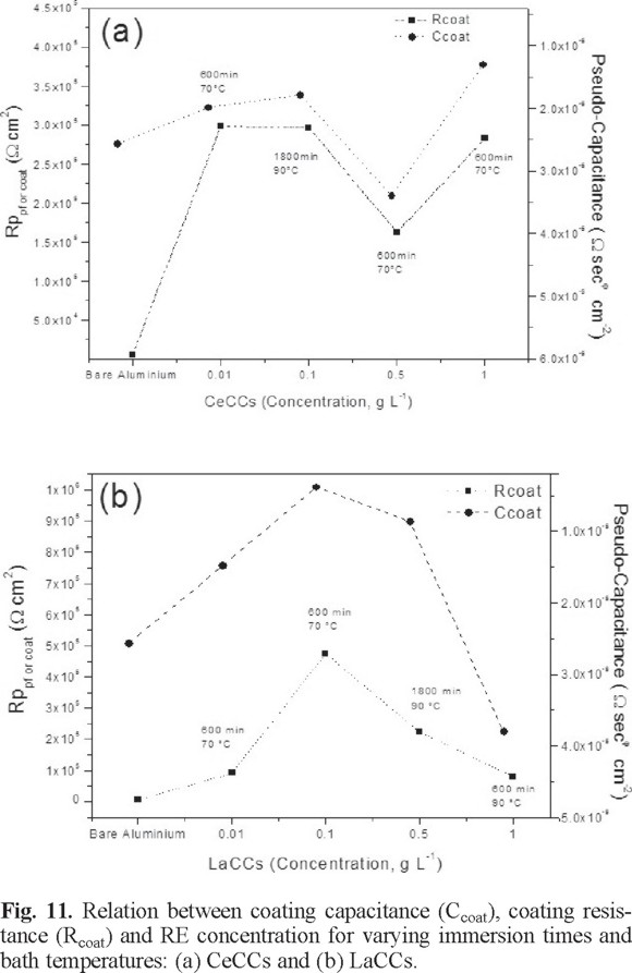
From Figure 11 and equation 7, it was computed that the average improvements of Rp for the CeCCs are 11.10 ± 0.54, 70.75 ± 3.58, 29.12 ± 1.45, and 50.55 ± 1.45 times, using an ion concentration of 0.01, 0.1, 0.5, and 1.0 g L-1, correspondingly; whereas for the same concentration for lanthanum, the polarization resistances are 22.34 ± 1.54, 117.05 ± 2.73, 39.95 ± 1.60, and 14.56 ± 0.46, respectively.
In summary, it has been established that treatments of AA6061 aluminum alloys by thermal activation up to 70°C in a RE(NO3)x ion solution with a concentration lower than 0.5 g L-1 allow the formation of an oxide/hydroxide layer over the intermetallic and aluminum oxide composite film that covers the metal matrix [56] with sufficient thickness and uniformity to provide a higher level of protection than the room temperature treatments. As a consequence, Rp is increased to large values depending on an adequate combination of ion concentration, and bath immersion time, although this last variable above 600 min exhibits a small contribution to the barrier properties. Thus, suitable conditions promote the interaction between the native Al2O3 layer and the RE layers, which are responsible for film sealing, adhesion, and anti-corrosion properties of the conversion layers. In addition, the characteristic signs of corrosion (pits) usually start at zones around the intermetallic particles that normally appear upon evaluation in the frequency region of 0.1 Hz, which are missing during the EIS measurements. In this regard, it has been suggested that the electrochemical nature of the corrosion of totally immersed specimens that are susceptible to pitting is usually determined by the diffusion of oxygen to cathodic sites. When this happens, the total weight loss of the specimens can be proportional to the area of the liquid surface [57], and the physical state of the corrosion products can affect the reaction progress. Thus, the surface characteristics formed during cerium and lanthanum conversion layer depositions seem to be optimal at 0.1 g L-1, 1800 min, 90 °C and 0.1 g L-1, 600 min, 70 °C, respectively, leading to a surface with no micro-defect evidence (pores or cracks) through which the penetration of water and Cl-1 ions can take place.
Finally, it can be stated that lanthanum oxides/hydroxides are more effective than cerium compounds in inhibiting corrosion of this aluminum alloy because it improves the dielectric properties of the metallic surface leading to a better insulating barrier.
Brief Characterization and Composition of surface corrosion products
The surface characterization and composition of the RECCs on the AA6061 aluminum alloy were also analyzed by SEM and XPS techniques to verify the compounds formed in the films after electrochemical evaluation.
The SEM micrographs at different magnifications of the corrosion product layer generated on the as-coated samples that exhibited the best and the poorest barrier properties for each RE ion concentration after 1200 min of exposure to a 3.5 wt% NaCl solution are shown in Figure 12 a-c. The sites chosen for SEM investigation were restricted to the central exposure area. As it can be seen in Figure 12a-b, the samples that exhibited a maximum corrosion resistance for LaCCs (0.1 g L-1 , 70 °C, 600 min) and CeCCs (0.1 g L-1, 90 °C, 1800 min), basically show films with surface morphologies that are quite similar to the original sample before EIS evaluation. The products that were formed during the corrosion process were fine, dense and homogeneous. The chemistry of the hydrated cerium/lanthanum oxides-hydroxides seems to be very rich, leading to different levels of hydration and different degrees of crystalline order and disorder. The width and density of the cracks declined significantly under these conditions, which is probably the main reason for the increase in Rp. On the other hand, coated samples with lanthanum conversion treatments featuring poor anticorrosion properties (1 g L-1, 70°C, 600 min) show important changes in the coating morphology (Figure 12 c), perhaps because the coarse structure of the corrosion product layer includes the cracks and porosities generated during the evaluation with the aggressive NaCl solution. The images display typical attacks of the LaCCs in chloride solutions, with some local dissolution produced pores. In these zones, the conversion layer begins to be covered with some white corrosion products on the surface. Magnification of the surface reveals that the layer has a spongy texture with deep cavities that reach the substrate surface. Semispherical pits of different sizes grew on the surface of these samples. In fact, with the exposure time, these samples behaved as bare aluminum. Once started, the dissolution process continues down through the pores. Changes in the surface morphology of the as-deposited RECCs after electrochemical measurements highlight the importance of the structure and morphology, which depend on the deposition parameters. Thus, layers created by using RE ion concentrations above 0.5 g L-1 and 70 °C are more porous, cracked, and permeable than the other ones.
The compositions and structure of selected RE coatings after being exposed to a 3.5 wt% NaCl solution are shown in Figure 13. From XRD for CECCs at the optimal deposition conditions (0.1 g L-1, 90 °C, 600 min), strong peaks attributable to metallic aluminum and alumina are detected, whereas a specific observation demonstrated that peaks of compounds attributable to CeO2 and Ce(OH)3 are apparent in the conversion layer after electrochemical evaluation (see Figure 13a). Weak signals of intermetallic compounds that were formed during the coating process are also detected (e.g., Al4Ce). Although the characteristic white corrosion product is not clearly visible in these RE coatings from SEM observations, near the agglomerates, the corrosion products contain CeCl3. XRD of LaCCs (0.1 g L-1, 70 °C, 1800 min) display similar features in comparison with the CeCCs although, in this case, the strong, well-defined signals suggest the formation of intermetallic Al4La (Figure 13b). The presence of LaCl3 and La(OH)3 and the missing peaks of the characteristic corrosion products from the substrate such as Al(OH)3 and AlCl3 support the assumption that the film remains on the substrate surface. XRD patterns of samples that exhibited unfavorable barrier properties show that the typical white corrosion products that are formed in chloride solutions correspond to a combination of LaCl3, La(OH)3, and Al4La, and the Al(OH)3 and AlCl3 soluble species (Figure 13c). Ren and Zuo [58] stated that two main modes may control the initiation of the pit in the aluminum substrate: either the absorbed Cl- ions are transported through the oxide film by means of oxygen vacancies or Cl- ions migrate to the Al2O3/aluminum boundary through defects at the surface, thus proposing the formation of soluble species such as Al(OH)3 and AlCl3, and in a second step, their dissolution. The proposal may explain the corrosion enhancement in our samples when the films presented crack morphology.

To analyze the oxidation state of cerium and lanthanum present in the conversion layer and confirm the presence of the corrosion products that are formed after the electrochemical evaluation, XPS analyses were carried out. Figure 14a-b shows the low resolution XPS spectra of selected samples after electrochemical tests. From the results, it is seen that the surface compositions contain O, Al, and different amounts of cerium or lanthanum, depending on the applied coating. C is observed and is probably due to the accumulation of contaminants during the exposure to air [59, 60], whereas Na and Cl are missing in the XPS spectra.

High resolution spectra of coated samples that displayed the highest charge polarization resistances at each RE ion concentration after EIS evaluations for CeCCs and LaCCs are shown in Figure 15 and 16 (a-h), respectively. The O1s, Ce3d, and La3d spectra for these samples are similar to those obtained before the electrochemical tests. Therefore, the spectra were curve-fitted with two peaks to quantify and deconvolute the contribution of each species (element associations) that comprises the spectra. All the high-resolution XPS spectra envelopes were curve fitted to the minimum number of peaks required for an optimum fit and the most probable components.
The O1s spectrum shows different binding energies at 528.5 eV, 530.0 eV, and 532.2 eV, which are associated with Ce oxide and Al oxide, respectively (Figure 15 a-h) [47]. In all the analyzed samples, the Ce3d peaks are composed of two groups of spin-orbit coupled peaks. Based on these spectra, the peaks at 882.3 and 900.7 eV are assigned to Ce4+, while the couples at 885.9 and 904.1 eV are assigned to Ce3+. The Ce3+/Ce4+ atomic ratios present in the film after electrochemical measurements for the selected specimens for Ce ion concentrations of 0.01, 0.1, 0.5, and 1 g L-1 are 0.723, 0.886, 1.11, and 0.884, respectively. This suggests that in samples where Ce is predominantly in oxidation state IV, a better electrochemical performance is exhibited and of these, the samples with uniform films (formed with low metal ion concentrations) have enhanced barrier properties for the aluminium alloy. The reason for the atomic ratio variations can be explained as follows: Ce in coatings tends to remain or be oxidized to Ce4+ in the presence of atmospheric oxygen and condensed moisture, whereas Ce3+ could be converted into Ce4+ by the precipitation of cerium hydroxides and oxides at cathodic sites of the aluminium alloy. As a consequence, pH is raised in the vicinity of a defect area. However, at low pH, Ce3+ is stable and more difficult to be oxidized (Ce3+ →Ce4+), but if that happens, the film protection may be reduced considerably.
By considering the states of both Ce and O, it can be proposed that the CeCCs are mainly composed of cerium oxide (CeO2), or hydroxides (Ce(OH)4), although an important quantity of Ce3+ in the form of Ce2O3 and Ce(OH)3 is also present.
On the other hand, similar O1s spectra are observed for the samples treated with lanthanum. In this case, the binding energies at 530.0 and 532.2 eV may be attributed to oxygen in the form of La oxide and hydroxide, respectively (Figure 16 a-h). La 3d high-resolution spectrum shows a doublet with a binding energy at 835.0 eV, characteristic of La3+. Frequently, it is assumed that La layer/corrosion products are thick enough to prevent detection of the aluminum signal coming through, the fraction of the aluminium surface covered by La can be presented approximately by the La/(La+Al) atomic ratio.
From this ratio, it was found that 73.1, 82.1, 63.4 and 34.5 % of the treated aluminum surface was covered with lanthanum after exposure to La concentrations of 0.01, 0.1, 0.5, and 1 g L-1, respectively. Also, the O/(La+Al) ratio can help to determine the form of lanthanum oxide/hydroxide that has been formed because the Al oxide/hydroxide layer remains constant, i.e, it is not affected by the temperature of the baths. The ratio was close to 3, corresponding to La(OH)3. The O1s and La3d spectra show that the La ion concentration is more important than the bath temperature and immersion time. The La3d spectra illustrate that the distance between the binding energies corresponding to La3+ varies with the concentration, indicating that at higher La ion concentrations, the internal stress that provokes cracking during film formation also accelerates the coating degradation.
Finally, the intensity of the XPS peaks is correlated with the corrosion protection enhancement. For example, samples coated with 1.0 g L-1 at 90 °C for 600 min for CeCCs, and with 1.0 g L-1 at 90 °C for 600 min for LaCCs, poor electrochemical performance is displayed, and also very noisy Ce3d and La3d peaks are exhibited, which are hard to fit and understand the contribution of RE compounds. By comparing the conversion treatments of both rare earth ions, it can be inferred that the deposition of lanthanum oxide/hydroxide features higher thermal stabilization in comparison with that of cerium oxide/hydroxides.
Experimental
Preparation of rare earth conversion treatments and coatings
The process to prepare conversion coatings has been previously described [30], but for clarity some parts are described here. Disc-shaped specimens, 0.025 m in diameter and 0.002 m in thickness, were used in this study. Prior to chemical treatments to remove surface contamination, the substrates were polished with 2000 paper grit, degreased, and cleaned with a soapy distilled water-acetone solution, and then dried under room conditions. Different coating variables were investigated: rare earth solution concentration (0.01, 0.1, 0.5, and 1 g L-1), solution immersion time (60, 600, and 1800 min), and bath temperature (50, 70, and 90 ºC). The natural pH of the solutions was maintained constant in each solution, which ranged from 3.9 to 4.6 and 3.5 to 5.1 for cerium and lanthanum ions, respectively. pH is one of the most important parameters in determining the morphology of the RE conversion coatings, and significant changes in this variable can produce non-reproducibility of coating morphology and composition. However, as pH is required for the precipitation of oxide/hydroxide compounds, and it takes place over a pH range, the measured values in this work favored the conversion process.
Analytical grade chemicals were used to prepare the solutions. Chemical conversion coatings were obtained with cerium (Ce(NO3)3 • 6H2O) and lanthanum La(NO3)3 • xH2O nitrates using 80 mL of the solution. The treated specimens were stored in a desiccator after drying in air at room temperature.
Electrochemical techniques, Tafel plots and EIS
Corrosion protection of coated samples was assessed by using Tafel Plots and electrochemical impedance spectroscopy (EIS). The evaluations were performed with a Gamry ZRA Reference 600 potentiostat connected to a personal computer. All the experiments were carried out by triplicate using 100 mL of a 3.5 wt% NaCl aqueous solution, at room temperature, which was prepared by using analytical grade NaCl and deionized water. The solution was unstirred during the experiments and its pH was 6.3. A conventional three-electrode electrochemical cell consisting of an acrylic cylindrical box (inner diameter: 0.013 m, length: 0.037 m), and samples with exposed area of 1.33 cm2 were used. A large-area graphite bar and Ag/AgCl (0.197 V vs Standard Hydrogen Electrode, SHE) were used as the counter and reference electrodes, respectively. The specimens were introduced at moderate pressure against an o-ring to avoid localized damage of the conversion layers. Tafel plots were acquired in the region from -250 mV vs. Eocp to +250 mV vs Eocp, whereas EIS measurements were carried out in the frequency region from 105 to 0.01 Hz (ten frequency points per decade) with amplitude of 10 mV rms. The impedance data were fitted to appropriate equivalent circuits using a complex non-linear-least-squares fitting routine, using both the real and imaginary components of the data.
Chemical and morphological analyses
Chemical and morphological characterizations of the surface before and after electrochemical evaluations were performed by X-ray photoelectron spectroscopy (XPS) and scanning electron microscopy (SEM/ EDS). XPS analyses were carried out on coated samples using an AES-XPS PHI-548 spectrometer in which the samples were excited by an unmonochromatized Al Kα line at 1486.6 eV. The working pressure was < 1 × 10⁻¹⁰ Pa. The energy scale was calibrated using thick copper films with a line at 932.67 eV for the Cu 2p3/2 transition. Survey scans were obtained in the range from 1205 to (-10) eV energy interval at 1.0 eV per step, and pass energy of 100 eV. Additionally, the high-resolution XPS scans were completed at 0.2 eV energy steps and pass energy of 50 eV (the constant pass energy mode). The measured full-width half maximum (FWHM) for the Cu 2p3/2 line in the metallic state with these settings is 1.6 eV. These detailed scans were recorded for Al 2p, Ce 3d5/2, C 1s, O 1s, Cl 2p3, and Na 1s after electrochemical evaluations. The analyzed area of the XPS measurements is 800 μm2.
Scanning electron microscopy and energy dispersive X- ray spectrometry (SEM/EDS) were employed to characterize the surface morphology of the RE conversion coatings, using a JEOL JSM-5300 equipped with an EDS 117 voyager Tracor Northern Spectrometer. Scanning electron microscopy was also carried out after electrochemical evaluations on the conversion process. The samples treated in the rare earth baths for relatively long times were covered with either a gold or a carbon thin film (2 nm) in order to reduce charging effects caused by the conversion coating. Due to the energy of the electron beam, for Al at 15 kV, the penetration depth is in the order of a few microns, and a strong background signal from the aluminum substrate is always present.
Conclusions
A series of solutions containing 0.01, 0.1, 0.5, and 1 g L-1 of Ce or La ions as Ce(NO3)3 or La(NO3)3, respectively, were used to analyze the effect of varying bath temperature (50, 70, or 90 °C) and immersion time (60, 600, or 1800 min) to form protective conversion films on AA6061 aluminum alloy. The following conclusions can be drawn from these studies:
Examination of the Tafel plots indicates that variation of these three parameters in the RE conversion treatments modified the general behavior of the anodic and cathodic branches of coated samples as a consequence of the morphology and the microstructure of the conversion layers that were formed. A reduction in cracks and porosity in the films yielded Tafel slope variable values, indicating that there was a mechanism change from a Volmer reaction ,as the rds in the range of ~ 120 mV dec—1, to a mechanism in which the cathodic process is controlled by concentration polarization rather than by activation polarization. RE conversion treatments (RE = Ce or La) of AA6061 aluminum alloys by thermal activation up to 70 °C in a RE(NO3)x solution with an ion concentration lower than 0.5 g L-1 allowed the formation of an oxide/hydroxide layer over the thin, robust intermetallic aluminum oxide film that covers the metal matrix with sufficient thickness and uniformity to provide a high level of protection to the underlying aluminum alloy, which is in contrast with room temperature treatments. Thus, Rp is increased to high values depending on a suitable combination of RE ion concentration, bath temperature, and immersion time, although a value for this last variable, more than 600 min, provides a low contribution to the barrier properties. The EIS results support the reduction of the film pitting corrosion by inhibiting cathodic and/or anodic reactions and increasing the overall polarization resistance values. After electrochemical tests, the SEM images indicate that the conversion films with the highest RE ion concentration lost their electrochemical properties, featuring a behavior similar to that of bare aluminum. For the Ce and La coatings, samples formed at low RE concentrations, the XRD patterns and XPS feature the presence of LaCl3, La(OH)3, CeCl3 and Ce(OH)3, which are consistent with SEM observations and indicate that the protective films remain on the aluminum substrate surface. Finally, with optimized experimental conditions, lanthanum baths are better than CeCCs in limiting the corrosion current density up to 102.52 times, which is related to the higher thermal stabilization of lanthanum oxide/hydroxide compounds in comparison with those displayed by cerium oxide/hydroxides.
Acknowledgements
The authors acknowledge the financial support provided by CONACYT, COFAA-IPN, SIP-IPN 2013-0706 and SNI-CONACYT. The authors thank M. Sc. E. Aparicio, Mr. I. Gradilla, Q. Ana C. Espíndola-Flores, M. E. Adela E. Rodríguez-Salazar, Dr. Paul E. Riley (Peace Corps) and Mr. D. Domínguez for their technical support.
References
1. Hinton B. R. W. J Alloys Compd. 1992, 180, 15-25. [ Links ]
2. Decroly, A.; Petitjean, J.-P. Surf. Coat. Technol. 2005, 194, 1-9. [ Links ]
3. Monteiro, F. J.; Barbosa, M. A.; Gabe, D. R.; Ross, D. H. Surf. Coat. Technol. 1988, 35, 321-331. [ Links ]
4. Kiyota, S.; Valdez, B.; Stoytcheva, M.; Zlatev, R. M.; Bastidas J. J. Rare Earths 2011, 29, 961-968. [ Links ]
5. Hamdy, A. S.; Beccaria, A. M. J. Appl. Electrochem. 2005, 35, 473-478. [ Links ]
6. Dabalá, M.; Armelao, L.; Buchberger, A.; Calliari, I. Appl. Surf. Sci. 2001, 172, 312-322. [ Links ]
7. Aldykewicz, A. J. J.; Isaacs, H. S.; Davenport, A. J. J. Electrochem. Soc. 1995, 142, 3342-3350. [ Links ]
8. Hughes, A. E.; Gorman, J. D.; Miller, P. R.; Sexton, B. A.; Paterson, P. J. K.; Taylor, R. J. Surf. Interface Anal. 2004, 36, 290-303. [ Links ]
9. Arenas M. A.; De Damborenea, J. J. Electrochim. Acta 2003, 48, 3693-3698. [ Links ]
10. Hosseini, M.; Ashassi-sorkhabi, H.; Ghiasvand, H. A. Y. J. Rare Earths 2007, 25, 537-543. [ Links ]
11. Indira, K. S.; Subramanian, R.; Shenoi, B. A. Met. Finish 1971, 69, 53-58. [ Links ]
12. Mishra, A. K.; Balasubramaniam, R. Corros. Sci. 2007, 49, 1027-1044. [ Links ]
13. Campestrini, P.; Terryn, H., Hovestad, A. Surf. Coat. Technol. 2004, 176, 365-381. [ Links ]
14. Arnott, D. R.; Ryan, N. E.; Hinton, B. R. W. Applications Surf. Sci. 1984, 22-23, 236-261. [ Links ]
15. Bethencourt, M.; Botana, F. J.; Cano, M. J. Appl. Surf. Sci. 2004, 238, 278-281. [ Links ]
16. Arenas, M. A.; Conde, A.; De Damborenea, J. J. Corros. Sci. 2002, 44, 511-520. [ Links ]
17. Aballe, A.; Bethencourt, M.; Botana, F. J. J. Alloys Compd. 2001, 323-324, 855-858. [ Links ]
18. Xingwen, Y.; Chunan, C.; Zhiming, Y. Corros. Sci. 2001, 43, 1283-1294. [ Links ]
19. Pourbaix, M. Atlas of electrochemical equilibria in aqueous solutions, National Association of Corrosion Engineers, New York, 1966. [ Links ]
20. Hayes, S. A.; Yu, P.; O'Keefe, T. J.; O'Keefe, M. J.; Stoffer, J. O. J. Electrochem. Soc. 2002, 149, C623-630. [ Links ]
21. Shore, S. G.; Knoeppel, D. W.; Deng, H.; Liu, J.; White III, J. P.; Chun, S.-H. J. Alloys Compd. 1997, 249, 25-32. [ Links ]
22. Stoffer, J. O.; O'Keefe, T. J.; Morris, E.; Hayes, S.; Yu, P.; Pittman M. Polym. Mater. Sci. Eng. 2000, 83, 311-312. [ Links ]
23. Smith, C. J. E.; Baldwin, K. R.; Garrett, S. A.; Gibson, M. C.; Hewins, M. A. H.; Lane, P. L. Acta Tech. Belgica Metall. 1997, 37, 266-273. [ Links ]
24. Mansfeld, F.; Wang, V.; Shih, H. J. Electrochem. Soc. 1991, 138, L74-L75. [ Links ]
25. Mansfeld, F.; Wang, V.; Shih, H. Electrochim. Acta 1992, 37, 2277-2282. [ Links ]
26. Tang, J.; Han, Z.; Zuo, Y.; Tang, Y. Appl. Surf. Sci. 2011, 257, 2806-2812. [ Links ]
27. Stoffer, J. O.; O'Keefe, T. J.; Lin, X.; Morris, E.; Yu, P.; Sitaram, S. P. Electrodeposition of cerium-based coatings for corrosion protection of aluminum alloys, U.S. Patent # 5,932,083, August 3, 1999. [ Links ]
28. "Cleaning, Alkaline" Process Specifications 12030 Revision M, McDonnell Douglas (now Boeing), St. Louis, MO; 1994. [ Links ]
29. Zhao, D.; Sun, J.; Zhang, L.; Tan, Y.; Li, J. J. Rare Earths 2010, 28, 371-374. [ Links ]
30. Brachetti-Sibaja, S. B.; Domínguez-Crespo, M. A.; Torres-Huerta, A. M.; De la Cruz-Hernández, W.; Onofre-Bustamante, E. Electrochem. Soc. 2012, 159, C40-C57. [ Links ]
31. Hu, J.; Zhao, X.; Tang S. W.; Ren, W. C.; Zhang, Z. Y. Appl. Surf. Sci. 2007, 253, 8879-8884. [ Links ]
32. Heller, D. K.; Fahrenholtz, W. G.; O'Keefe, M. J. Mater. Charact. 2011, 62, 1071-1075. [ Links ]
33. Hinton, B. R. W. Metal Finishing 1991, 89, 55-61. [ Links ]
34. Davenport, A. J.; Isaacs, H. S.; Kendig, M. W. Corros. Sci. 1991, 32, 653-663. [ Links ]
35. Rivera, B. F.; Johnson, B. Y.; O'Keefe, M. J.; Fahrenholtz, W. G. Surf. Coat. Technol. 2004, 176, 349-356. [ Links ]
36. Kutz, M. Handbook of Environmental Degradation of Materials, William Andrew Inc., New York, 2005. [ Links ]
37. Bibber, J. W. Metal Finishing 2001, 99, 15-22. [ Links ]
38. Fedrizzi, L.; Bianchi, A.; Deflorian, F.; Rossi, S.; Bonora, P. L. Electrochim. Acta 2002, 47, 2159-2168. [ Links ]
39. Montemor, M. F.; Simoes, A. M.; Carmezim, M. J. Appl. Surf. Sci. 2007, 253, 6922-6931. [ Links ]
40. Kobayashi, Y.; Fujiwara, Y. Electrochim. Acta 2006, 51, 4236-4242. [ Links ]
41. Metikos-Hukovic, M.; Babic, R.; Grubac, Z.; Brinic, S. J. Appl. Electrochem. 1994, 24, 325-331. [ Links ]
42. Martins, N. C. T.; Moura e Silva, T.; Montemor, M. F.; Fernandes, J. C. S.; Ferreira, M. G. S. Electrochim. Acta 2008, 53, 4754-4763. [ Links ]
43. Goeminne, G.; Terryn, H.; Vereecken, J. Electrochim. Acta 1998, 43, 1829-1838. [ Links ]
44. Campestrini, P.; Westing, V.; Wit, J. H. Electrochim. Acta 2001, 46, 2631-2647. [ Links ]
45. Goeminne, G.; Terryn, H.; Vereecken, J. Electrochim. Acta 1995, 40, 479-486. [ Links ]
46. Moutarlier, V.; Gigandet, M. P.; Normand, B.; Pagetti, J. Corros. Sci. 2005, 47, 937-951. [ Links ]
47. Palomino, L. E. M.; Aoki, I. V.; De Melo, H. G. Electrochim. Acta 2006, 51, 5943-5953. [ Links ]
48. Johnson, B. Y.; Edington, J.; O'Keefe, M. J. Mater. Sci. Eng. A 2003, 361, 225-231. [ Links ]
49. Mac Donald, J. R.; Kenan, W. Impedance Spectroscopy, Emphasizing Solid Materials and Systems, Wiley and Sons, New York, 1987. [ Links ]
50. Jütner, K. Electrochim. Acta 1990, 35, 1501-1508. [ Links ]
51. Rammelt, U.; Reinhard, G. Corros. Sci. 1987, 27, 373-382. [ Links ]
52. Pang, J.; Briceno, A.; Chander, S. J. Electrochem. Soc. 1990, 137, 3447-3454. [ Links ]
53. Brug, G. J.; Van der Eeden, A. L. G.; Sluyters-Rehbach, M.; Sluyters, J. H. J. Electroanal. Chem. 1984, 176, 275-295. [ Links ]
54. Hitzig, J.; Juttner, K.; Lorenz, W. J.; Paatsch, W. Corros. Sci. 1984, 24, 945-952. [ Links ]
55. Scully, J. R.; Silverman, D. C.; Kendig, M. W. Electrochemical Impedance: Analysis and Interpretation, ASTM STP 1188. Pa, USA, 1993. [ Links ]
56. Bethencourt, M.; Botana, F. J.; Cano, M. J.; González-Rovira, L.; Marcos, M.; Sánchez-Amaya, J. M. Metal. Mater. Trans. A 2012, 43A, 182. [ Links ]
57. Aramaki; K. Corros. Sci. 2001, 43, 2201-2215. [ Links ]
58. Ren, J.; Zuo, Y. Surf. Coat. Technol. 2005, 191, 311-316. [ Links ]
59. Pan, M.; Meng, G. Y.; Xin, H. W.; Chen, C. S.; Peng, D. K.; Lin, Y. S. Thin Solid Films 1998, 324, 89-93. [ Links ]
60. Zhang, H.; Zuo, Y. Appl. Surf. Sci. 2008, 254, 4930-4935. [ Links ]

