


Services on Demand
Journal
Article
 English (pdf)
 Article in xml format
 Article references
 Send this article by e-mail
Indicators
-
 Cited by SciELO
 -
 Access statistics
Related links
-
 Similars in
SciELO
Similars in
SciELO
Share

 Permalink
Journal of the Mexican Chemical Society
Print version ISSN 1870-249X
J. Mex. Chem. Soc vol.58 n.3 Ciudad de México Jul./Sep. 2014
Article
Construction and Testing of a Novel in-situ Photoelectro-Fenton System Based on an Arrangement of a Carbon Sponge and a Carbon Steel Plate
Ivonne Arely González Reyes, M. E. de Anda Reyes, Francisco J. Rodríguez Valadez, Juan Manríquez, Erika Bustos, Adrian Rodríguez, Luis A. Godínez*
Centro de Investigación y Desarrollo Tecnológico en Electroquímica, Parque Tecnológico Querétaro Sanfandila, Pedro Escobedo, 76703, Querétaro, Mexico. lgodinez@cideteq.mx
Received February 6th, 2014
Accepted April 3rd, 2014.
Abstract
A novel photoelectro-Fenton system was built by coupling a carbon sponge (CS) with a carbon steel plate (CSP). When this system contacts a solution containing orange II dye (OGII) under ultraviolet (UV) irradiation, 68% of the solution color was removed compared with 0% without UV irradiation. The tests indicate that the CS-CSP arrangement releases iron ions, a phenomenon associated with the removal of 23% of the solution color, a percentage similar to that obtained when Fe2+ and Fe3+ salts are directly placed into the dye solution. The identification of oxidizing free radicals and the color removal percentages indicate that the CS-CSP coupling can operate as in situ Fenton process.
Keywords: in situ, photoelectro-Fenton, carbon sponge cathode.
Resumen
En este trabajo se construyó un sistema fotoelectro-Fenton novedoso mediante el acoplamiento de una esponja de carbón (EC) con una placa de acero al carbón (PAC). Al colocar este arreglo con una solución del colorante naranja II (OGII) irradiando luz ultravioleta, se logró remover el 68% del color de la solución, comparativamente con el 0% obtenido cuando no se aplicó luz UV. Las pruebas realizadas indican que el arreglo EC-PAC libera iones de hierro y que este fenómeno está asociado a la remoción del 23% del color de la solución, porcentaje similar al que se obtiene cuando se colocan sales de Fe2+ y Fe 3+ directamente en la solución del colorante. La identificación de la formación de radicales libres oxidantes cuando se usa el arreglo EC-PAC y los buenos porcentajes de remoción obtenidos son indicios de que el acoplamiento EC-PAC puede estar actuando como un proceso Fenton in situ.
Palabras clave: In situ, fotoelectro-Fenton, cátodo de esponja de carbon.
Introduction
The use of water in industrial processes has introduced diverse contaminants, identified as health risks, into residual waters. Among the most important contaminants are heavy metals [1-4], hydrocarbons [5] and organic compounds [6-8], which are generally considered toxic or dangerous. To treat the organic contaminants, various techniques have been proposed, of which biological treatments are most accepted. However, when the residual water contains organic compounds of poor biodegradability, this treatment exhibits limited efficiency. In this context, advanced oxidation processes (AOPs) emerge as alternative treatments for successfully removing this group of contaminants. Advanced oxidation processes are characterized by the production of •OH free radicals that possess a high oxidizing power and can mineralize organic contaminants in water. Among the best-known AOPs, the Fenton process is one of the most popular since it generates •OH radicals from the reaction between hydrogen peroxide (H2O2) and iron (Reaction 1). A variant to the Fenton concept is the electro-Fenton process in which hydrogen peroxide is generated from the electrochemical reduction of the O2 in the water (Reaction 2). During this process, the current applied to the system can also reduce Fe3+ to Fe2+ (Reaction 3), regenerating the Fe2+ necessary for the Fenton reaction (Reaction 1).
Fe2+ + H2O2 → Fe3+ + •OH + OH− (1)
O2 + 2H+ + 2e− → H2O2 (2)
Fe3+ + e− → Fe2+ (3)
When the electro-Fenton process is carried out in the absence of UV light, a peroxi-coagulation process can take place since Fe(OH)3 is produced. This effect is promoted by accumulation of the Fe3+ species as shown by Reaction 1 (9). In this case, a coagulation process carries out the removal of pollutants. Although different studies performed using electro-Fenton [10-11] and photo-assisted electron-Fenton [12-13] processes report the efficient degradation of various contaminants, most of the electrochemical cells involve complex designs and arrangements of the electrodes and require an external voltage source. The development of in situ Fenton processes could provide an alternative to the conventional electro-Fenton processes via systems capable of generating free radicals without requiring an external potential. In our earlier studies, we confirmed that a TiO2-C nanocomposite exposed to ultraviolet radiation can increase hydrogen peroxide generation by reducing the O2 in the carbon contained in the composite [14-15]. In contrast, Tryba et al. prepared TiO2-C-Fe nanocomposites and observed that the arrangement functions as an in situ Fenton system, capable of oxidizing organic compounds in contact with it [16-17]. In the present research, a photoelectro-Fenton system was built by coupling a carbon sponge and a carbon steel plate (a concept which is similar to that of the iron-air battery (18)), which is then irradiated with ultraviolet light. The obtained results indicate that the arrangement can operate as in situ Fenton system to remove the color of an orange II dye (OGII) solution.
Experimental Section
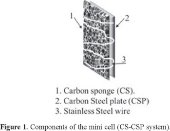
This system is formed by coupling a carbon sponge (CS) cathode and a carbon steel plate (CSP) anode, both 8 mm × 25 mm, using a stainless steel wire that joins both components (Figure 1).
The degradation tests were performed by placing a 10 ml sample of the OGII dye (C16H11N2NaO4S, Aldrich) with a pH of 3 and a concentration of 10 mg/L in a beaker. The CS-CSP system, including the wire that joins the components, was immersed in the dye solution, and ultraviolet light was applied using a low-pressure Hg lamp (UVP Inc., P = 75 mW/cm2 and λ = 354 nm). The dye concentration was determined from the absorbance at 487 nm using a UV-Vis Hach model DR/4000U spectrophotometer. To quantify the iron dissolved from the CS-CSP, the system was immersed in a Na2SO4 (0.05 M) solution, pH 3, and irradiated with ultraviolet light. The iron content of the solution was determined after contact using cyclic voltammetry with an Epsilon potentiostat and a three-electrode cell consisting of a gold working electrode, an Ag/Ag reference electrode and a platinum counter electrode. In contrast, to determine the effect of iron in the solution on the OGII discoloration, 10 ml of the dye and a 5 µg/L Fe2+solution, prepared from an FeSO4 salt, were added and irradiated with ultraviolet light for one hour. The absorbance at 487 nm was measured at the end of the process to evaluate the color disappearance. The effect of Fe3+ was similarly evaluated by adding an FeCl3 salt to the solution. Afterwards, to verify any effect of the contact between the surface of the carbon sponge and the dye, the elemental composition was determined via Energy Dispersive X-Ray Spectroscopy (EDS) using an scanning electron microscope (JEOLJSM5400LV); in addition, images were obtained with an optical microscope using a 10× objective and a beam width of 50 μm. Finally, to verify that the electrode arrangement operates as a Fenton process, the free radicals generated by the CS-CSP arrangement were quantified using N,N,-dimethyl-p-nitrosoaniline (RNO, Sigma Aldrich) and measuring the decrease in absorbance at 350 nm. [19]
Results and Discussion
Color removal efficiency by the CS-CSP system
The efficiency of the dye degradation process under varying conditions is provided in Table 1. The results indicate that when the electrode system is used (CS-CSP) on a solution saturated with O2, 68% of the color is removed from the solution. When the solution is saturated with N2, the removal percentage decreases to 18%, demonstrating that oxygen must be present in the solution to achieve efficiency. To enhance the effect of dye adsorption on the system components, the same test was performed using CS and CSP separately. For the CSP case, removal percentages of 25% and 5% were obtained in solutions saturated with oxygen and nitrogen, respectively; while for the CS, 4% was removed from the solution containing O2 and 0% from that containing N2. When the experiments were performed without ultraviolet light, the solution color was maintained in all cases, thus making ultraviolet irradiation a decisive factor in the discoloration process.
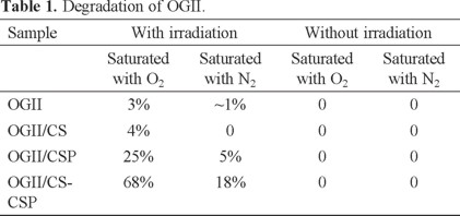
Figure 2 presents the processes that could occur in the system with the UV irradiation dissolving the iron (Fe2+ and Fe3+) from the CSP. The electrons produced when the iron is dissolved are transferred to the carbon, which reduces the oxygen present in solution to generate hydrogen peroxide. The interaction between the generated H2O2 and the dissolved iron produces free radicals, which can oxidize the dye, thus removing the solution color.
Iron dissolution in the CS-CSP system via cyclic voltammetry
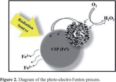
Previous studies have proposed that iron could dissolve from an Fe0 source, a phenomenon that could be utilized to carry out a Fenton process. To identify the release of iron by the CS-CSP system, cyclic voltammetry was performed. Figure 3a provides the voltammograms obtained at the beginning of the test (Figure 3a), at 10 min (Figure 3b) and at 60 min (Figure 3c). The tests performed at 10 and 60 min exhibit oxidation and reduction signals that are identified with the Fe2+/Fe3+ redox pair; the voltammograms also demonstrate that the peak current increases from 10 to 60 min as the iron concentration increases in the solution due to the dissolution from the CS-CSP system. When the same test is performed without ultraviolet light at 60 min of contact (Figure 3d), these current peaks are also observed with much lower intensity, indicating that the dissolution rate is lower without UV irradiation.
The Fe0 dissolution process was described by Liao et al. [20], who proposed an oxidation from Fe0 to Fe2+initiated by the adsorption of water molecules onto the metallic iron surface (Reaction 4), followed by the formation of hydroxides (Reactions 5, 6 and 7), and ending with the dissolution of Fe2+ ions in the acidic solution (Reaction 8).
Fe + H2O → Fe(H2O)ads (4)
Fe(H2O)ads → Fe(HO−)ads + H+ (5)
Fe(HO−)ads → (FeOH)ads + e− (6)
(FeOH)ads → (FeOH)+ads + e− (7)
(FeOH)+ads + H+ → Fe2+ + H2O (8)
In this process, two electrons are released into the bulk solution through a metal-ligand charge transfer process, which could reduce the OGII and decrease the solution color.
Effect of Fe2+ and Fe3+ in the solution on the discoloration process
To the presence of iron ions in the OGII degradation, tests were performed using dissolved Fe2+ and Fe3+ salts as an iron source under ultraviolet irradiation. The results indicate that 23% of the color present in the solution is removed in both cases, regardless of the iron source. This value coincides with the percentage removed using the carbon steel plate, 25% (Table 1). According to the previous results, the iron dissolved from the CSP works in a manner similar to that of the iron salts in solution. This effect can be understood by considering the presence of superoxide radicals (O2−), which result from the Fe2+ promoted reduction of oxygen [21]. A similar behavior of Fe2+ and Fe3+ salts is explained by Tokumura et al. [22], who indicate that Fe3+ can be reduced to Fe2+ using ultraviolet light (Reaction 9).

According to this, Fe3+ located in the solution is firstly reduced to Fe2+, by Reaction 9, and later oxidized to produce (O2−) as previously described.
Superficial changes in the carbon sponge
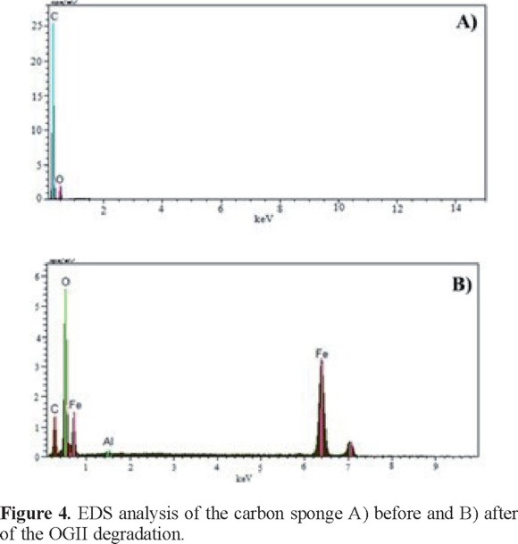
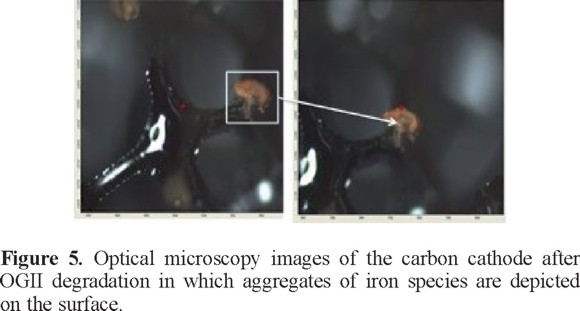
The elemental composition at the CS surface before and after the OGII degradation process was obtained via EDS (see Figure 4). The results indicate the appearance of iron after the CS-CSP system was used to remove the color from the solution (Figure 4B) because part of the iron dissolved in the steel plate is deposited onto the carbon sponge. This finding was corroborated with optical microscopy images (Figure 5) in which reddish deposits, characteristic of iron compounds, can be observed on the CS surface.
Generation of free radicals using the CS-CSP arrangement.
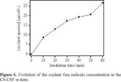
Figure 6 depicts the change in the amount of free radicals during the degradation of the dye using the CS-CSP system. The free radicals concentration clearly increases with the contact time up to 26 x 10−8 mol after 60 minutes of treatment. By observing the oxidizing free radicals formation, there is evidence that the CS-CSP system can operate as an in situ Fenton process.
Conclusions
The as-obtained results indicate that the CS-CSP system can efficiently degrade OGII, removing 68% of the color from the solution when irradiated with ultraviolet light. Cyclic voltammetry indicated that the CSP releases iron ions, a phenomenon that also requires irradiation with ultraviolet light. The effect of the iron released by the CSP is similar to the use of Fe2+ and Fe3+ solutions in the dye because in both cases 23% of the color can be removed when brought into contact with the OGII. The color loss can be related to a reduction in the dye molecules possibly caused by the electrons generated in the Fe0 desorption process or by the reaction with the Fe2+ dissolved in the solution. The determination of the free radicals generated in the CS-CSP system and the color removal indicate that the system could acts as an in situ Fenton process.
Acknowledgments
The authors are grateful for the support of the National Council for Science and Technology (CONACyT) [Consejo Nacional de Ciencia y Tecnología, for its initials in Spanish], project SEP-CONACyT-2008/106590. M. E. de Anda Reyes thanks CONACyT for supporting her postdoctoral research.
References
1. Harraz, F.A.; Abdel-Salam, O.E.; Mostafa, A.A.; Mohamed, R.M.; Hanafy, M. J. Alloys and Comp. 2013, 551, 1-7. [ Links ]
2. Eliet, V.; Bidoglio, G. J. Environ. Sci. Technol. 1998, 32, 3155-3161. [ Links ]
3. Stafiej, A.; Pyrzynska, K. Sep. Purif. Technol. 2007, 58, 49-52. [ Links ]
4. Afkhami, A.; Madrakian, T.; Karimi, Z.; Amini, A. Colloids Surf. A. 2007, 304, 36-40. [ Links ]
5. Shengyong, L.; Qiulin, W.; Di, W.; Xiaodong, Li.; Jianhua, Y. Environ. Prog. Sustain. En. 2012, 32, 458-460. [ Links ]
6. Kabra, K.; Chaudharg, R.; Sawhneg, R.L. Ind. Eng. Chem. Res. 2004, 43, 7683-7696. [ Links ]
7. Babuponnusami, A.; Muthukumar, K. Environ. Sci. Pollut. Res. 2013, 20, 1596-1605. [ Links ]
8. Sherrald, K.B.; Marriott, P.J.; Amiet, R.G.; Colton R.; Mccormick, M.J.; Smith G.C. Environ. Sci. Technol. 1995, 29, 2235-2242. [ Links ]
9. Boye, B.; Marieme, D.M.; Brillas E. Electrochim. Acta 2003, 48, 781-790. [ Links ]
10. Guivarch, E.; Trevin, S.; Lahitte, C.; Oturan, M.A. Environ. Chem. Lett. 2003, 1, 38-44. [ Links ]
11. Garrido-Ramírez, E.G.; Mora, M.L.; Marco, J.F.; Ureta-Zañartu, M.S. Appl. Clay Sci. 2013, 86, 153-161. [ Links ]
12. El-Ghenymy, N.; Oturan, J.A.; Garrido, P.L.; Centellas F.; Rodríguez, R.M.; Brillas, E. Chem. Eng. J. 2013, 234, 115-123. [ Links ]
13. Yuan, S.; Gou, N.; Alshawabkeh, A.N.; Gu, A.Z. Chemosphere 2013, 93, 2796-2804. [ Links ]
14. Peralta-Hernández, J.M.; Manríquez, J.; Meas-Vong, Y.; Rodríguez, F.J.; Chapman, T.W.; Maldonado, M.I.; Godínez, L.A. J. Hazard. Mater. 2007, 147, 588-593. [ Links ]
15. Peralta-Hernández, J.M.; Meas-Vong, Y.; Rodríguez, F.J.; Chapman, T.W.; Maldonado, M. I.; Godínez, L.A. Water Res. 2006, 40, 1754-1762. [ Links ]
16. Tryba, B.; Morawski, A.W.; Inagaki, M.; Toyoda M. Appl. Catal. B: Environ. 2006, 63, 215-221. [ Links ]
17. Tryba, B. J. Hazard. Mater. 2008, 151, 623-627. [ Links ]
18. Narayanan, S.R.; Surya Prakash, G.K.; Manohar, A.; Yang, B.; Malkhandi, S.; Kindler, A. Sol. State Ion. 2012, 216, 105-109. [ Links ]
19. Muff, J.; Bennedsen, L.R.; Sogaard, E. G. J. Appl. Electrochem. 2011, 41, 599-607. [ Links ]
20. Liao, C.H.; Kang, S.F.; Hsu, Y.W. Water Res. 2003, 37, 4109-4118. [ Links ]
21. Qiao, X.; Chen, S.; Tan, L.; Zheng, H.; Ding, Y.; Ping, Z. Magn. Reson. Chem. 2001, 39, 207-211. [ Links ]
22. Tokumura, M.; Morito, R.; Hatayama, R.; Kawase, Y. Appl. Catal. B: Environ. 2011, 106, 565-576. [ Links ]

