


 nueva página del texto (beta)
 Español (pdf)
 Artículo en XML
 Referencias del artículo
 Enviar artículo por email
 Citado por SciELO
  Similares en
SciELO
Similares en
SciELO 
 Permalink
Introduction
Nowadays the use of optimization methods for solving structural problems has become very common because of their advantages versus conventional structural design methods. The lightest and stiffest structures can be designed by optimization methods, nevertheless they are very difficult to manufacture because these methods generate irregular and complex geometries, similar to those found in nature. Based on their experience, designers make several subjective decisions in order to simplify these geometries and make them manufacturable, at the expense of losing optimality. Some techniques have been developed to obtain regular geometries from optimized solutions without that losing. Chyi-Yeu & Shin-Hong [1] developed an algorithm based on an artificial neural network to identify geometrical patterns in optimized geometries; then these patterns are superpositioned to simplify the geometries. The main disadvantage is the limited number of regular geometries available. Ming-Hsiu & Yeh-Liang [2] and Yeh-Liang, Ming-Sho & Chuan-Tang [3] present automatic algorithms to interpret structures from a topological solution; with these methods the geometric irregularities are minimized, however the final geometry is still very irregular and complex, therefore quite difficult to manufacture.
The material distribution in geometries optimized by topological optimization is related with the structural functionality, which means material tends to be added and concentrated along areas where stress level is high, and eliminated along areas where stress level is low [4, 5]. The material distribution provides information to interpret the topological results as material paths.
Adaptation methodologies imply that designers have to make several decisions about which geometries are suitable to modify a geometry optimized by topological optimization. In the simplest approach, designers interpret that result as material paths along the design domain, as is shown in Figure 1; thereby the layout of material paths has a strong subjectivity. For that reason it is interesting to propose an automatic adaptation method, based in a computational algorithm, capable to generate material paths without subjectivity.
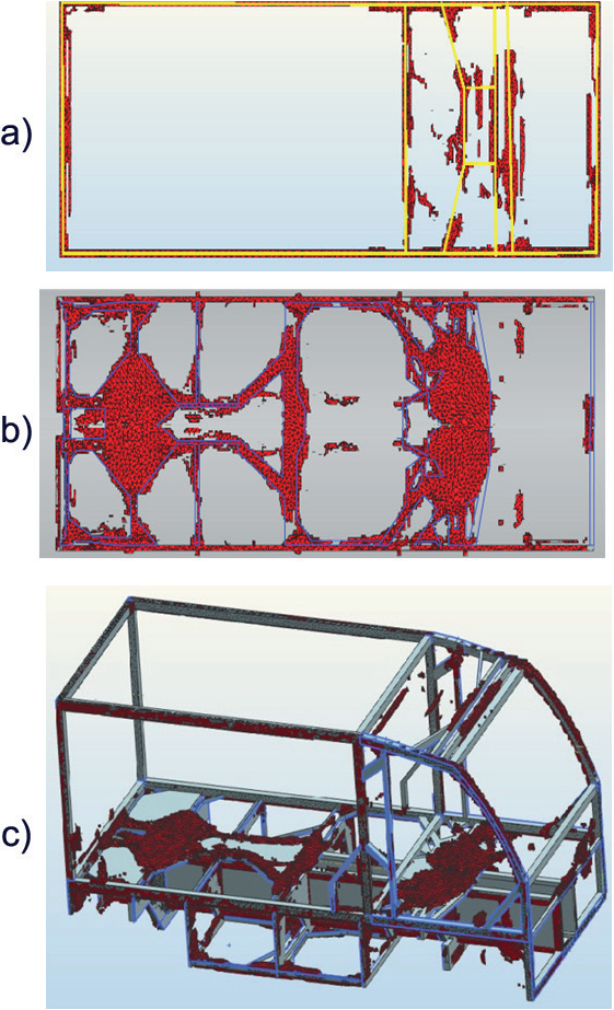
Figure 1 Structural optimization of an electric delivery car [6]. a) and b) show material paths adapted by a designer, c) Representation of the car with standard structural members. The subjectivity in the final result is quite high.
The adaptation method presented in this work is based on skeletonization, which is a morphological operation for image processing that transforms a binary image into its minimum representation (called skeleton) without losing its topological characteristics. Although there are several approaches for skeletonization process (morphological operators [7], curve evolution [8], level sets [9], among others), for all of them the skeleton of any geometry is a thin version of it, which is equidistant to its boundaries; in this way, topological properties of the geometry are emphasized instead of being lost. Once the skeleton is obtained, the vertices or intersections are identified. Subsequently, based on their connectivity, paths in the skeleton are replaced with straight lines. These lines represent structural members, whose cross-sectional dimensions are determined by size optimization. The final result is a structure that preserves optimal topological characteristics without subjectivity.
2. Method
In the following sections the method proposed is described. The set of steps is constituted for:
Skeletonization.
Vertices localization.
Vertices connectivity and straight lines generation.
Minimum length application.
2.1 Skeletonization
Skeletonization is an iterative process that consists in making a binary image thinner and thinner until its thickness is one pixel. The result is a set of connected paths that is known as skeleton, which preserves the base lines and connections that characterize the geometry, i.e. its topology. This operation is also known as medial axis transformation [10, 11] because all the lines are equidistant to the border of the geometry (Figure 2).
2.2 Vertices Localization
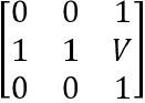
Once that skeleton is generated, the vertices or intersections are located. In this paper a vertex (V) is defined as a pixel where three or more paths converge. The skeleton is transformed in a matrix, where a white pixel is 1 and a black pixel is 0, therefore paths are represented by 1's in the matrix.
After, a submatrix of order 3x3
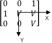
At the end of this process, all the inner vertices are found. In the other hand, there are two particular types of vertices that do not follow the described rule: 1) vertices at the start or the end of a path and 2) vertices with loads or constrains (boundary conditions). The Figure 3 shows a vertex type 1, for this vertex the sum of the adjacent positions is 1. For the type 2 the vertex must be identified explicitly.

If several paths concur at the same vertex, the described process generates a neighborhood of vertices (Figure 4). In order to obtain a single vertex in a neighborhood the following process is proposed, which is based on centroid calculation of a plane geometry.
First, the 3x3 submatrix is centered in each vertex (V) of the neighborhood and a local coordinate system is defined (Figure 5). The local coordinates of the centroid (
and

, where i goes from 1 to 3,
2.3 Vertices Connectivity and Straight Lines
The next step is to identify the vertices at the start and the end of each path, in order to replace these paths with straight lines. For this purpose the 3x3 submatrix is located in a vertex (start of the path) to identify adjacent pixels with value 1, these pixels indicate the direction of each path connected to the vertex. Then, the 3x3 submatrix is centered in one of the adjacent pixels with value 1. If the submatrix contains another vertex, this is the end of the path and its connectivity is defined by the start and end vertices; else the submatrix is centered in the next pixel with value 1 in the path until another vertex is reached. This process is repeated for each pixel with value 1 adjacent to the start vertex. (Figure 7).
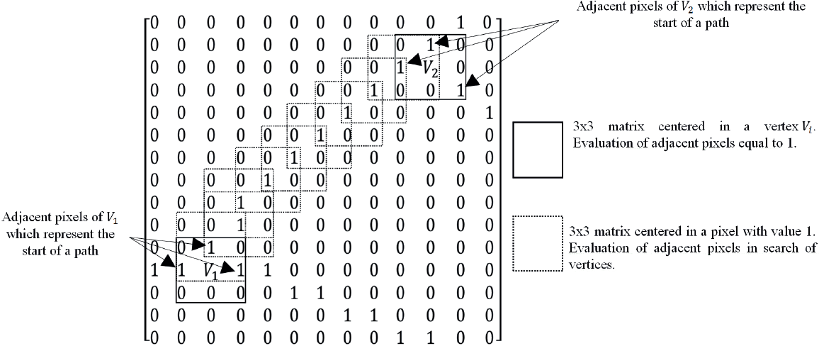
Figure 7 Connectivity between vertices V 1 and V 2 . Once the start and end vertices are found, the connectivity of a path is defined
When the connectivity of all the paths is known, these are replaced with straight lines. In this way the irregular topological result is transformed into a geometry topologically identical, but simpler than the original one. The structure obtained is called skeleton-structure.
2.4 Minimum Length Algorithm
The skeleton-structure might contain some very short members that hinder the manufacture process. For this reason the minimum length algorithm creates a submatrix that covers the vertices whose distance among them is less than a minimum value. This submatrix has the double size of the minimum length value, translated in pixels, in order to consider all the neighborhood of vertices that are very close; the minimum length must be specified explicitly.
The algorithm calculates a new vertex using the equation (2) but, given that the length of the submatrix is twice the minimum length, the distance of the vertices is recalculated until the vertices that do not fulfill the condition are vanished. This process is repeated until all the members which do not fulfill the minimum length are suppressed into a single vertex.
3. Case Study: the Short Cantilever Beam
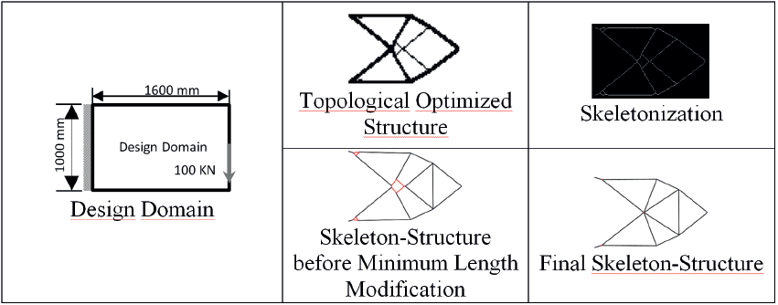
As an application example, the short cantilever beam problem is addressed. The result of the topological structural optimization of the design domain and its adaptation based on the proposed method is shown in the Table 1. Evidently the final skeleton structure generated is topologically quite similar to the topological optimized structure.
In this example the standard member in Figure 8 is selected (the selection of a feasible cross section is not considered in this paper, so it has to be a decision of the designer.); its cross-sectional dimensions are generated via size optimization. The objective is to define the optimal dimensions of the cross section to resist the boundary conditions (constrains and loads). The size optimization process is performed using OptiStruct from the Altair HyperWorks® software.
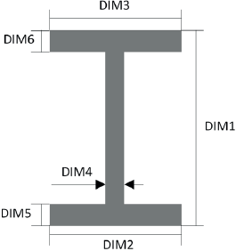
All the straight lines are meshed with 1D finite elements as is shown in Figure 9. The cross-sectional dimensions are considered as design variables, whose initial values are presented in Table 2. The objective function is set to minimize the compliance for a mass percentage of 25%. Structural steel ASTM A36 is selected as the material of the structure.

Table 2 Cross-sectional initial dimensions
| Dimension | Initial Value mm |
|---|---|
| DIM1 | 127 |
| DIM2 | 76 |
| DIM3 | 76 |
| DIM4 | 5.4 |
| DIM5 | 8.3 |
| DIM6 | 8.3 |
The results of the optimal solution are shown in Table 3. In order to select a standard member, the S75x8.5 member is chosen because its dimensions are the closest to the optimal results.
Table 3 Optimal cross-sectional and S75X8.5 dimensions.
| Dimension | Optimum Values mm | S75x8.5 Shape mm |
|---|---|---|
| DIM1 | 78.82 | 76 |
| DIM2 | 36.45 | 59 |
| DIM3 | 36.45 | 59 |
| DIM4 | 2.459 | 4.3 |
| DIM5 | 3.963 | 6.6 |
| DIM6 | 3.963 | 6.6 |
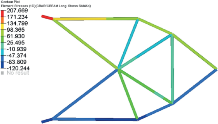
FEA is applied to the structure considering the S75x8.5 standard member to evaluate the performance of the structure [12]. In Figure 10 the maximum stress in each bar is shown. The Safety Factor (SF) of the structure is 1.2.
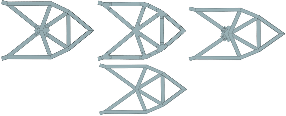
Finally, in order to complete the structural design, four different options for connections are presented, considering that all the joints are bolted or welded (Figure 11).
4. Other Cases Study
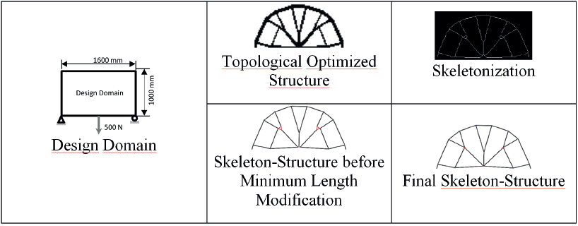
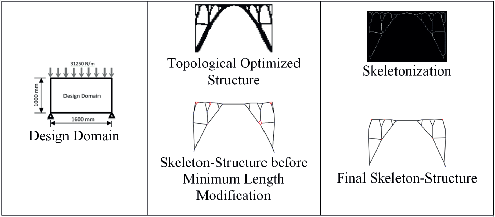
The following Table shows the results of applying the proposed algorithm to other two classical optimization problems: Michell's structure and a bridge structure [13]. In both cases the efficient performance of the algorithm is proved. Once again the topology of the optimal structure is preserved, without the loss of optimality associated with subjective decisions.
5. Conclusions
The adaptation algorithm presented is useful for topologically optimized structures because it transforms a non-manufacturable structure into a totally manufacturable one. Once the algorithm is applied, the skeleton-structure obtained preserves, without subjectivity, the topology of the optimal solution.
The minimum length algorithm allows the designer to control the existence of short members, which hinder manufacture, without affecting the topology significantly. Size optimization allows to select an appropriate standard member, which ensures withstand the boundary conditions.
In the first case study, the purpose of showing four different options for connections is to emphasize that even though the presented algorithm generates a unique solution for a specific structure, the problem of automatically generating connections has not been solved yet.
Adaptation for manufacturing of topologically optimized structures can be a very difficult issue for a person, because it strongly depends on that person's experience. The method presented in this work eliminates that dependence, which means a very convenient tool for structural design. In this sense, an optimized structure can preserve its optimality after manufacturing.

