


 nueva página del texto (beta)
 Inglés (pdf)
 Artículo en XML
 Referencias del artículo
 Enviar artículo por email
 Citado por SciELO
  Similares en
SciELO
Similares en
SciELO 
 Permalink
Introduction
Conjugate heat transfer studies in closed cavities have many engineering applications, such as solar collectors, nuclear reactors, cooling of electronic systems, building design applications, etc. In particular, theoretical research in building thermal design provides the opportunity to quantify the heat transfer in complex systems in order to obtain thermal parameters required in commercial software or for making decisions at different building design stages. Also, it is well known that the interaction between indoor spaces and the environment is highly influenced by the type of building materials (thermophysical and optical properties): opaque and/or semitransparent walls. Thermal energy gains or losses through the envelope directly affect the thermal comfort of occupants and the final energy consumption inside rooms. On the other hand, building occupants are the main source of CO2 emissions inside rooms, making mandatory the analysis of coupling heat and mass transfer in order to satisfy indoor air quality standards. Therefore, conjugate natural convection with surface radiation, mass transfer and conducting walls in closed cavities are worthy of research. A short literature review is presented next. For example, in 1976 Larson and Viskanta [1] reported a numerical study of conjugate heat transfer in a square cavity with opaque and diffusive walls. The authors found that thermal radiation is dominant. Weeb and Viskanta [2] included the heat condition through a semitransparent wall, showing that 70% of the energy incoming to the cavity was provided by direct absorption of thermal radiation. Later, Behnia et al. [3] analysed a closed cavity with a semitransparent wall considering convective losses to the surroundings. They studied the effect of external convection and surface thermal radiation on heat transfer inside the cavity. Kwon et al. [4] reported the effect of considering a glazed surface in the middle of vertical conductive wall in the closed cavity. More recently, Álvarez and Estrada [5] considered a semitransparent wall with a solar film adhered to the inside surface. They found that total energy transferred to the air through the glass wall with a control film is lower than the case of the simple clear glass. Zhao et al. [6] investigated the fluid flow and heat transfer in square enclosures representing building elements. They evaluated conjugated heat conduction and natural convection in laminar flow regime. Results reveled that heat transfer rates across both enclosures are complex functions of the volume ratio scale, Rayleigh number, and the relative thermal conductivity. Xamán et al. [7-10] reported several studies of conjugate heat transfer in closed cavities with conducting walls in laminar and turbulent flow regimes. They have analysed the effect of solar control coatings on heat transfer, surface thermal radiation contribution, and the effect of different roof materials on thermal comfort inside cavities with real room sizes. In the same way, Kuznetsov and Sheremet [11-18] published several works of conjugate heat transfer in enclosures with finite thickness heat-conducting walls at different physical conditions. For example, they reported the effect of local heat sources at different positions, heat transfer problems with internal mass transfer, the analysis of convective and radiative heat exchange with the environment on particular wall surfaces, numerical investigations at different flow regimes (laminar and turbulent), analysis of steady or unsteady conditions, two or three dimensional enclosures and, finally the contribution of temperature and concentration gradients on heat and mass transfer (double diffusive phenomena). Gijón-Rivera et al. [19] presented a numerical simulation for a room on top a building considering natural convection and surface thermal radiation with opaque and semitransparent walls interacting with surroundings by convection and radiation. Authors reported a sensitive analysis of the effect of windows and the coupled-decoupled solutions on indoor air temperatures and thermal loads inside rooms. Finally, Serrano-Arellano and Gijón-Rivera [20] reported a numerical solution of conjugate heat (convection-radiation) and mass transfer in a square cavity filled with a mixture of Air-CO2. They found that convection increases as the mass transfer is taking into account but decreases as the Rayleigh number increases.
As it is observed in the state of art, there are only few studies of conjugate heat transfer (turbulent convection, radiation and conduction) inside enclosures due to its complexity. Thus, we can say that there has not been found a conjugate heat transfer study with a conducting wall in a closed cavity filled with a contaminated fluid (Air-CO2) in turbulent flow regime. The purpose of the present work is to analyse the effect of heat conduction of different conductive walls on conjugate heat and mass transfer by turbulent natural convection of a room modeled as a square cavity. Four different building materials typically used in Latin-American countries (warm climates), such as Mexico and Peru are selected as the conductive wall configurations: red brick, clear glass, concrete block and adobe block. Statistical information shows that 14.6% of Mexican houses are built of adobe walls, followed by 69.5% made of red brick [21]. Otherwise, government information from Peru shows that the most common wall material used to build houses is the red brick or concrete block with 51.5%, followed by the adobe block with 34.1% [22]. Adobe is a construction material formed by a mixture of straw and mud used since pre-Hispanic age and typically used for building rustic houses. Nowadays the adobe block is deeply used in medium and high-income houses in Mexico.
Physical and Mathematical Models
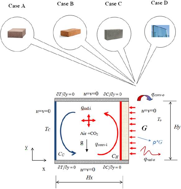
A two-dimensional closed cavity filled with a mixture of Air-CO2 is shown in Fig.1. The working fluid is initially considered to be at rest with a uniformly distributed temperature and concentration inside the cavity. The square cavity can be assumed to be of infinite depth along z axis. The left vertical surface of the cavity is considered to be an isothermal opaque wall at 25°C (TC) with a CO2 concentration of 500 ppm (CC) The horizontal top and bottom wall are considered adiabatic and impermeable. The right vertical surface is considered as a conductive wall with three different building materials (opaque and semitransparent): case A (adobe block), case B (red brick), case C (concrete block) and case D (single clear glass); this vertical surface is kept at a higher CO2 concentration of 3000 ppm (CH). On the vertical conductive surface an incoming normal uniform and constant solar radiation flux of 736 W/m2 (AM2) was considered and two dimensional heat transfer by conduction is taken into account. Furthermore, in the conductive wall take place a temperature difference between external surface and the environment allowing the presence of convective and radiative heat fluxes to the exterior. In the case of the semitransparent surface, part of the energy is reflected, part is transmitted through and part is absorbed by the wall, whereas in the case of the opaque surface the radiative energy transmitted through it is not considered. The semitransparent and opaque walls of the cavity were considered gray, diffusive, reflective, and radiation emitter surfaces. The thermal fluid was considered steady, radioactively non-participating. The Boussinesq approximation is assumed with constant thermophysical and optical properties are the integrated spectrum values. Finally, thermophysical properties were calculated by using the methodology reported by Reid et al. [23].
Convective mathematical model
The convective mathematical model is formulated taking into account several assumptions such as: non-slip condition at walls is valid. Any chemical reaction and heat generation/dissipation inside the enclosure is not considered. The energy flux produced by mass transfer (Dufour effect) and the mass flux produced by the energy transfer (Soret effect) are not considered. The contaminant is considered at lower density than the air (raising motion). The working fluid is considered as a Newtonian fluid in steady state. The governing equations for turbulent natural convection in a square cavity are the average equations of mass, momentum, energy and species presented below:
In order to close the turbulence mathematical problem, the turbulent kinetic energy (k) and the turbulent kinetic energy dissipation (ε) are required:
The k-ε turbulence model defines the following variables C ε1=1.44, C ε2=1.492, C ε3=tan h|ν/u|, Cμ =0.09, σ k =1.0 and σε=1.3 (HH model proposed by Henkes et al, [24]).
The boundary conditions of the mathematical convective model for the hydrodynamic, thermal and mass transport are as follows:
The velocity boundary conditions at solid surfaces are:
The thermal and mass boundary conditions are:
Heat conduction mathematical model
Fig. 2 shows the physical model of the conductive surface interacting with external and internal conditions. In order to calculate the energy transferred through the wall the conductive model is dominated by the differential heat conduction equation given by:
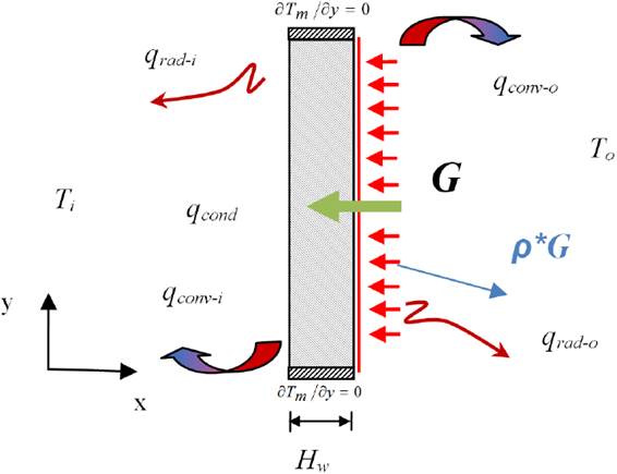
where λwall is the thermal conductivity, Twall is the temperature, Cpwall is the specific heat of the wall and Θ is the energy attenuation function by absorption and scattering, which depends on the extinction coefficient (Sg ) as Θ(x) = Gexp(-Sg (Hw-x)), not considered for opaque walls [25].
The wall thicknesses is considered as 6 mm for the semitransparent surface and 120 mm for the opaque surfaces under study. Thermal boundary conditions in the conductive surface are: adiabatic at lower (y = 0) and upper (y = Hy ) surfaces, that is ∂Twall/∂y = 0; in the zone in contact with the environment, a constant heat flux is imposed with convective and radiative losses to the ambient with a temperature To , that is to say, qcond-wall +α⋅G=qconv-0 + qrad-0 ( x = Hx+ Hwall ). In order to obtain the internal wall temperature distribution To , the following energy balance was conducted (x = Hx ): qcond-wall = qconv-i + qrad-i . Lastly, thermophysical and optical properties of the different conductive walls are shown in Table 1.
Surface thermal radiation model
The internal radiative exchange among surfaces was carried out by mean of the net radiation method described by Siegel and Howell [26]. All inner surfaces are considered to be opaque and diffuse except for the case of the semitransparent surface. The heat transfer by radiation from a surface is defined as the difference between the outgoing radiative energy (radiosty) and the incoming radiative energy (irradiance). The radiative heat flux for the j th element on each wall is given by the following energy balance:
where the radiosity for the j th element is defined as:
the irradiation is given by:
where the summation over the k th surface element is to be taken for those elements over the boundary for which j interacts radiatively and dFj-k is the differentially view factor, which is calculated using the crossed string method for the two-dimensional square cavity.
Numerical solution and verification
The set of transport differential equations are mathematically replaced by the general discretized in tensorial form as:
The generalized equation described above can be expressed as every particular transport equation where, ρ is the density of the mixture of fluid (kg/m3), uj is the velocity component (m/s), ϕ is the general transport variable, Γ is the diffusion coefficient and S ϕ is the source term. Once the mathematical model has been established, the spatial derivatives are discretized using the finite volume method suggested by Patankar [27] on a non-uniform staggered grid. The general convection-diffusion equation (1) is integrated on a control volume, obtaining an algebraic equation for each nodal point as:
From the above equation n y nb represent the number of iterations and the coefficients for the neighborhood nodes, respectively; b is the source term, and ϕ is the discrete dependent variable over each control volume. The convective terms are approximated by the power law scheme and diffusive terms by the central scheme. The false transient approach is used to increase the convergence of the numerical algorithm. The coupling between the mass and momentum equations is made with the SIMPLEC algorithm proposed by Van Doormal and Raithby [28]. The algebraic equations system is solved with the line by line method (LBL) with alternating direction implicit scheme (ADI). The solution converges when mass balance residuals are at least 10-8. A radiative balance over walls is iteratively treated in order to obtain net energy fluxes by radiation needed by the conjugate heat transfer model. The radiosity equations were solved by the Simpson´s rule and the view factors between the elements were obtained by the Hottel´s cross string method proposed by Modest [25].
The accuracy of the numerical results was verified through numerous tests based on the grid size effect. It was found an adequate mesh for 101(101 with non-significant differences for the velocity, temperature, concentration and for all the Rayleigh numbers under study. The numerical code developed in FORTRAN programing language have been deeply verified and validated using different problems from literature such as: (a) laminar natural convection and mass transfer in a differentially heated square cavity [29]; (b) the benchmark solution of natural convection with turbulent flow in a square cavity [30]; (c) the experimental results of the natural convection in turbulent flow regime in an air filled square cavity [31]; and, (d) the natural convection analysis with radiation in a differentially heated square cavity [32]. All these comparisons have been reported on diverse previous publications [19, 20]; from these comparison results and their good agreement, we considered our code sufficiently tested.
Results and discussion
The parameters of the study used to obtain the conjugate heat and mass transfer for the square cavity with conductive walls are describe next. The size of the cavity was varied from 0.5 to 2.0 m, which correspond to 2.56×10⁹ ≤ Ra ≤ 1.63×10¹¹. The solar radiation is considered as incident in normal direction on the conductive wall with a constant value of 736 W/m2 (AM2). The opaque wall has the thickness of a typical building block of 120 mm and the semitransparent wall thickness considered was 6 mm as a single clear glass sheet. Temperature on the isothermal wall (Tcold) is 25°C with a low CO2 concentration of 500 ppm (CL); whereas the conductive vertical wall was kept at a high CO2 concentration of 3000 ppm (CH). The external conditions existing over the conductive wall were: a heat transfer coefficient of 6.8 W/m2K (3 m/s) and an outdoor temperature of 308 K. A parametric study to evaluate the effect of the opaque and semitransparent wall on heat and mass transfer was performed taking into account the next building materials: case A (block adobe), case B (red brick), case C (block concrete) and case D (single clear glass).
Flow patterns inside the cavity (streamlines, isothermals and isoconcentrations)
The streamlines, isothermals and isoconcentration distribution for the different building materials in the conductive wall and for the interval of the Rayleigh number considered in this study are showed below. Streamlines contours for all cases of study are graphically presented in Fig. 3. As can be seen, a counterclockwise recirculating flow pattern inside the cavity is observed due to energy delivered by the conductive wall and buoyancy forces acting upon the fluid for all cases under study. It can be note that most marked differences in fluid motion are especially presented at lower Ra numbers. In particular, the case D for Ra = 2.56x10⁹ shows a core recirculation divided into two central zones, which produces a non-symmetrical flow distribution inside the cavity with slight flow fluctuations. As the Ra number increases, a symmetric behavior of the flow with regard to the centre of the cavity is observed. The fluid motion is concentrated in the zone near walls owing to high velocity gradients located in the boundary layer region (the fluid is confined at the centre of the space); this faster movement of fluid next to the boundaries is also an indication of higher levels of turbulence. For high values of Rayleigh (Ra ≥ 2.04x10¹⁰), at the centre of the cavity a main recirculation is formed, causing an important fluid stratification in the upper and bottom sides of the cavity for all wall materials.
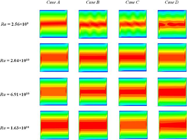
Fig. 3 Streamlines contours for all Ra numbers analysed: Case A (adobe block), Case B (red brick), Case C (concrete block) and Case D (single glass), from left to right, respectively.
Fig. 4 shows the isotherms patterns inside the cavity for all cases analysed. The thermal energy supplied from the vertical conductive wall of the cavity causes an upward movement of fluid until reaching the top of the cavity and towards the isothermal wall. In this zone, the fluid loses energy starting a descending movement in the direction of the bottom wall. At that time, a new rotation starts once again for finally reaching the thermal equilibrium. It can be observed that high horizontal thermal stratification occurs in most of the cavity for all Ra numbers. As the Ra number increases, the isotherms at the centre of the cavity are quasi-horizontal, becoming vertical over the boundary layer region and forming stratified multilayers throughout the cavity.

Fig. 4 Isotherms for all Ra numbers analysed: Case A (adobe block), Case B (red brick), Case C (concrete block) and Case D (single glass), from left to right, respectively.
As expected, the case D shows higher fluid temperatures inside the cavity due the nature of the semitransparent wall. However, an important finding was that the case A presents lower temperatures inside the cavity among cases. The cavity with wall made of adobe has temperature differences between 2 to 4°C compared to the case B and between 4 to 6°C with respect to the case C configuration. In general, as the Ra number increases, the fluid temperature in the bottom side of the cavity increases, remaining almost constant in the rest of the cavity, especially for the case of opaque walls. In addition, the lowest temperature differential (ΔT) is observed for the case A, which indicates that it has a more thermally homogeneous space inside the cavity. Finally, it can be seen how the stratification drastically diminishes from Ra = 6.91x10¹⁰ for the case D configuration; the cavity is divided into two big zones with uniform temperatures, covering approximately the 90% of the space. This thermal behavior is clearly different to those found in previous studies, such as [7], which can be attributed to the mixture of Air-CO2 considered inside the cavity (combined effect of conjugate heat and mass transfer).
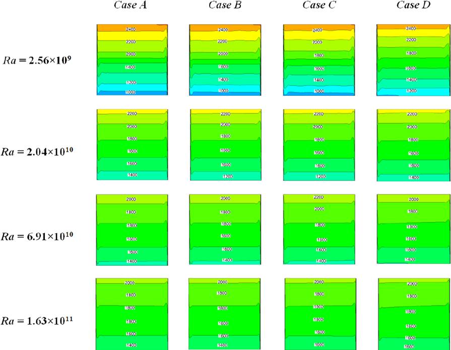
Fig. 5 shows the isococentration behavior at the inside of the cavity. In general, it can be noted that the CO2 concentration differential (ΔC) decreases as the Ra number increases from 1400 to 400 ppm for all cases considered in this study. Also, it can be seen that there exists a small influence of wall materials on CO2 concentration for all Ra numbers. However, it can be observed that the case B shows the lowest concentration levels with less than 200 ppm for all Ra numbers and among building materials. In general, case B can be adopted as an optimal configuration from the air quality standpoint.
Average fluid temperatures and heat fluxes from the wall to the interior of the cavity.
A quantitative comparison of the average fluid temperatures inside the cavity with different conductive walls is presented in Table 2. As we can see, average fluid temperatures for the case A are lower for all Ra numbers, decreasing by approximately 2, 4 and 10°C, regarding cases B, C and D, respectively.
Table 2 Average fluid temperatures inside the cavity.
| Ra | Case A | Case B | Case C | Case D |
|---|---|---|---|---|
| 2.56×10 9 | 34.1°C | 36.0°C | 37.9°C | 46.6°C |
| 2.04×10 10 | 35.3°C | 37.3°C | 39.2°C | 47.1°C |
| 6.91×10 10 | 36.1°C | 38.3°C | 39.9°C | 47.8°C |
| 1.63×10 11 | 37.4°C | 38.9°C | 40.2°C | 47.9°C |
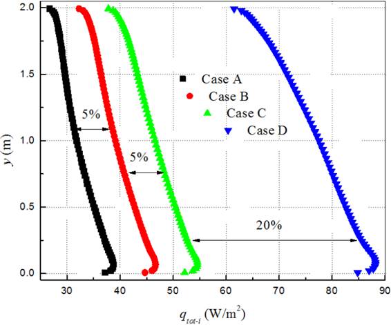
The average heat fluxes of the conductive wall for a Ra = 1.63×10¹¹ are graphically shown in Fig. 6. It can be seen that heat flux to the interior of the cavity is directly affected by the type of wall. The case A shows the lower heat fluxes to the interior of the cavity in agreement with indoor temperatures found previously. The case A (adobe block) decreases the energy delivery by the wall to the interior of the cavity by approximately 5, 10 and 30% regarding cases B, C and D, respectively. Concluding, the case A is the best choice in order to reach thermal comfort conditions inside the cavity. A qualitatively similar thermal behavior is observed for the rest of the Ra numbers considered in this study.
Dimensionless heat transfer
The variation of the local convective Nusselt number as function of the size of the conductive wall for Rayleigh numbers of 2.56×10⁹ and 1.63×10¹¹ are graphically shown in Fig. 7. It can be seen that for a Ra = 2.56×10⁹, the Nusselt number remains almost unchanged for different building materials with only slight differences at the bottom side of the wall. Furthermore, for a Ra =1.63×10¹¹ is clearly observed how the Nusselt number is affected by the type of the conductive wall. From the thermal point of view, we can see again the advantage of choosing the case A respect to other conductive walls. In general, the local Nu number increases as the size of the cavity (Ra) increases.
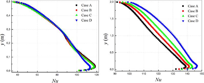
Fig. 7 Variation of local Nusselt number for the conductive wall. Cases: a) Ra = 2.56×10⁹, b) Ra = 1.63×10¹¹.
Table 3 presents the average convective, radiative and total Nusselt number as function of the Rayleigh number in order to quantify the contribution of different conductive walls on convection, radiation and total heat transfer inside the cavity. Here, we can see that the average convection contribution is higher than radiation by 6-10% for a Ra = 2.56×10⁹, except in the case D, where radiation contribution is higher than convection by around of 3%. As it can be noted, the same behavior is observed for higher Ra numbers, presenting differences in favor of radiation contribution between 170-186%. Therefore, it is important to consider that a conjugate heat transfer analyses (convection-radiation) cannot be neglected on this type of problems. Regarding overall heat transfer intensity among cases, it is observed that differences are higher as the Ra number increases. For a highest Rayleigh number (Ra = 1.63×10¹¹), the case A underestimates the case B by 2.5%, followed by the case C (4.9%), and finally by the case D (13.4%).
Table 3 Average convective, radiative and total Nusselt numbers for different conductive wall materials.
| Ra | Case A | Case B | Case C | Case D | ||||||||
|---|---|---|---|---|---|---|---|---|---|---|---|---|
| NuConv | NuRad | NuTot | NuConv | NuRad | NuTot | NuConv | NuRad | NuTot | NuConv | NuRad | NuTot | |
| 2.56×10 9 | 86.3 | 76.5 | 162.8 | 85.5 | 78.2 | 163.7 | 85.4 | 79.9 | 165.3 | 85.6 | 88.3 | 173.9 |
| 2.04×10 10 | 109.7 | 157.5 | 267.2 | 108.7 | 161.0 | 269.7 | 108.7 | 164.6 | 273.3 | 107.6 | 180.7 | 288.3 |
| 6.91×10 10 | 117.7 | 239.1 | 356.8 | 116.4 | 244.2 | 360.6 | 117.8 | 249.7 | 367.5 | 119.0 | 273.8 | 392.8 |
| 1.63×10 11 | 117.8 | 319.6 | 437.4 | 120.9 | 327.4 | 448.3 | 123.8 | 335.0 | 458.8 | 128.3 | 367.6 | 495.9 |
Note: Average Nusselt numbers are calculated at the hot wall (conductive surface).
Conclusions
In this paper, numerical calculations for the conjugate heat and mass transfer by natural convection in a square cavity filled with a mixture of Air-CO2 are presented. The closed cavity was analyzed considering a vertical conductive wall with a high concentration of 3000 ppm and an isothermal cold wall at 25°C with a CO2 concentration of 500 ppm; the horizontal top and bottom walls were considered adiabatic and impermeable. From the results, it can be concluded the next:
The lowest temperature differential (ΔT) is observed for the case A for all Ra numbers.
Thermal stratification is very different for case D at high Ra numbers compared to those found in the differentially heated square cavity problem. This behavior can be attributed to the contaminated fluid considered in this study.
There exists a minimum difference of 200 ppm in favor of case B regarding the contaminant concentration levels for all Ra numbers.
Average fluid temperatures for the case A are lower than cases B, C and D (2, 4 and 10°C, respectively) for all Ra numbers.
As the Rayleigh number increases, the average fluid temperature inside the cavity increases for all cases under study.
Higher radiation contribution is observed as the Ra number increases with maximum differences between 170-186%.
Finally, the case A was the best choice in order to reach thermal comfort conditions at indoor spaces such as rooms.

