


Services on Demand
Journal
Article
 English (pdf)
 Article in xml format
 Article references
 Send this article by e-mail
Indicators
-
 Cited by SciELO
 -
 Access statistics
Related links
-
 Similars in
SciELO
Similars in
SciELO
Share

 Permalink
Ingeniería mecánica, tecnología y desarrollo
Print version ISSN 1665-7381
Ingenier. mecáni. tecnolog. desarroll vol.4 n.4 México Mar. 2013
Artículos
Vibratory Forces and Synchronization in Physical Systems
Tadeusz Majewski
Departamento de Ingeniería Industrial y Mecánica, Universidad de las Américas-Puebla, Sta. Catarina Martir, Cholula, 72810 Puebla, México Teléfono: 01 46 (222) 229 26 73. tadeusz.majewski@udlap.mx
Fecha de recepción: 24-10-2012.
Fecha de aceptación: 10-01-2013.
Abstract
In this paper vibratory forces are studied. The paper presents some physical systems in which synchronization occurs. This phenomenon is a result of vibratory forces. Depending on the ratio of the frequency of excitation to the natural frequency, one can obtain contactless transmission of power or the elimination of vibration. The phase angle between two or more objects that move in unison depends on the parameters of the system. For some systems mathematical models, results of simulation, and properties are presented. It is shown that in each system with vibration there are inertial forces that can change the properties of the system, generate continuous angular or rectangular motion or can give an effect of synchronization.
Keywords: Synchronization, vibratory forces, mechanical systems, selfbalancing systems.
Resumen
En este trabajo se estudian las fuerzas vibratorias generadas en los sistemas mecánicos así como el fenómeno de sincronización en algunos sistemas físicos. Estas fuerzas son responsables del movimiento síncrono en diferentes sistemas mecánicos. Dependiendo de la razón de frecuencia de excitación y de la frecuencia natural es posible transmitir la potencia de un lugar a otro o eliminar las vibraciones. La fase del movimiento síncrono entre dos o más objetos depende de los parámetros del sistema. Se presentan algunos ejemplos en los cuales se ilustra el uso de las ecuaciones del sistema; define las fuerzas vibratorias, se describe el comportamiento síncrono y algunas de sus propiedades.
Palabras clave: Sincronización, fuerzas vibratorias, sistemas mecánicos, sistemas autobalanceados.
Introduction
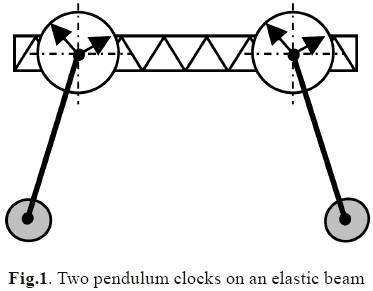
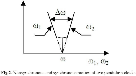
It has been observed by clock-makers that two clocks on an elastic beam or wall will start to move with the same rhythm but will move with distinct rhythms when separate. This phenomenon of synchronization was described by Huygens in the 17th century [1]. His explanation was unexpected. We now know that such behavior is a result of weak constraints between two clocks due to small vibrations that are transmitted between them. Very small vibrations of one clock are transmitted to the other resulting in the same rhythm in both clocks. When the difference between their rhythms is not great, after some time, the clocks move with the same frequency and the stable phase angle between them is zero or π. Fig. 1 presents two pendulum clocks and the connection between them, Fig. 2 presents the difference in their frequencies when they move in unison or independently.
In nature there are many examples of this phenomenon. However, engineers are more interested in the behavior of machines and this paper presents some examples from this area along with explanations as to why these effects take place, when synchronization takes place and what other effects can be obtained.
There are a few books and many articles on synchronization in different areas: nature, physics, mechanics, electronics, biology, and now also in society.
I.I. Blekhman, in his papers and books [2-4], showed many mechanical systems where synchronization takes place and also mentioned other systems with similar effects.
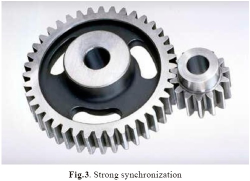
When objects are coupled by very rigid constrains the objects can move with any frequencies and any phase angles between them, e.g. two or more gears with different numbers of teeth - Fig.3.
When the objects are connected by weak constraints (elastic elements in mechanical systems) they are able to move with the same frequency or different frequencies, the some or opposite shift angles between them depending on the work conditions.
Two Rotors on the same Plate
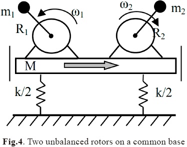
One classic example is the case of two unbalanced rotors on the same vibrating base - Fig.4. Initially they have different spin velocities ω1 and ω2 When the difference between them is not great they eventually start to rotate with the same velocity ω1<ω<ω2 The resultant spin velocity ω depends on the inertia of the objects and it is closer to the spin velocity of the object with greater inertia. The rotors may move in unison with the same or opposite phase angle.
W. Bogusz and Z. Engel [5, 6] described their experiments with two rotors. One rotor is driven by a motor and the second one is connected to a current generator. After the action of the vibration of the base x(t) the second rotor starts to rotate with the same velocity as the first one and drives a generator which produces electrical power to the order of kW. In the experiments they had to give the second rotor an initial velocity to obtain its synchronous motion with the first rotor.
The vibration of the base x(t) is dependent on the forces generated by both rotors. The parameters of the system: masses of the rotor's unbalance -m1, m2, the mass of the base with two rotors - M, the eccentricity of the rotors- R1, R2.
When two rotors move with the same speed ω1>=ω2>=ω (synchronous motion) then the vibration of the base is defined by the equation

where α is an angle that defines the position of the second rotor with respect to the first one.
The vibration of the base can be taken as

where φ is the shift angle between the excitation acting on the base and its response.
The motion of the second rotor (passive one) is a result of the inertial force acting on it from the base vibration - Fig.5. Its position with respect to the first rotor defines the equation

where c2 is a coefficient of the viscous resistance and
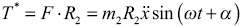
is a vibratory moment acting on the second rotor.
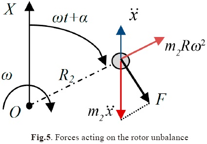
The right side of Eq.3 presents the moment T * given by the inertial force acting on the mass m2. The vibratory moment can be taken as the average during a period of vibration τ=2π/ω and the moment has a form
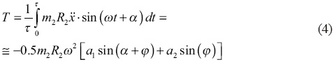
Fig.6 presents vibratory moment T as a function of the position of the second rotor with respect to the first one. It can be seen that the stable angle α for the second rotor is very close to zero - α≈0°. The passive rotor should deliver torque T1 to the current generator so the passive rotor moves with delay with the active rotor (Fig.6).
The two rotors move with almost the same phase if T1≈0 or with a shift angle for T1≠0. The vibratory moment T depends on the amplitudes of vibration a1, a2 generated by both rotors.
For the system (Fig.4) with the parameters: m1= 1 kg, m2= 0.7 kg, R1 = R2 = 0.1 m, ω=70 rad/s, ω/ω0 = 0.7 the maximum vibratory torque is Tmax ≈ 8 Nm (Fig.6). Of course only a part of it can be used for driving the generator.
It was shown that power may be transmitted from one rotor to another through the vibration of the base on which they are placed - this is considered contactless transmission of power because the rotors are not connected directly.
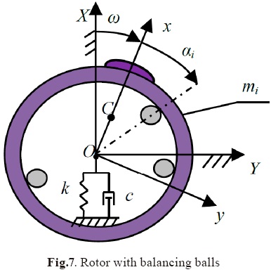
Selfbalancing System
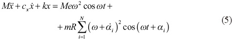
The author of this paper worked with automatic balancing of the rotors where synchronization took place [7, 8]. An unbalanced rotor has free elements in the form of balls, rollers or liquid inside the rotor or in a special drum fixed to the rotor. Under the action of vibratory forces, the free elements can change their position with respect to the rotor and changes in the rotor's unbalance. The behavior of a mechanical system depends on the forces that act on it. The rotor's unbalance generates vibrations and these then generate inertial forces which act on the free elements. Fig.7 presents an unbalanced rotor with a single degree of freedom and some free balls.
The rotor's vibration in x direction is governed by the equation
A relative motion of a ball with respect to the rotor
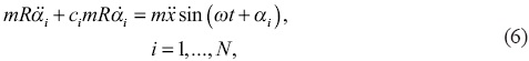
where N is the number of the balls.
The balls move inside the drum at low velocity.
The vibration of the rotor can be taken as
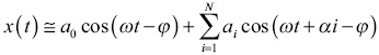
and the rotor acceleration

The vibratory force acting on the ball

And the average inertial force acting on ith ball
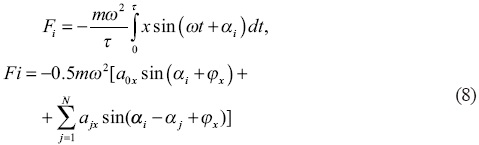
The vibratory force is the result of vibrations generated by the rotor's unbalance and all balls
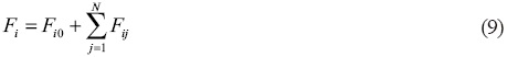
where
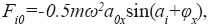
is the vibratory force generated by the rotor's unbalance and
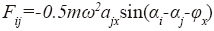
is the vibratory force from jth ball.
The vibratory force for balancing with only one ball is presented in Fig.8. Depending on the rotor speed the position of equilibrium of the ball can be at αf ≈ 0 or αf=π. For αf=π the system will be balanced if the static moment of the ball is mR=Me.
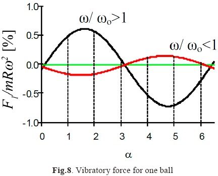
It is seen that only for ω>ωo does the ball occupy the position opposite the rotor's unbalance thus compensating for the unbalance. The ball's position α=π is stable for ω>ωo and unstable for ω>ωo. If the rotor has at least two balls then the balls can compensate an unbalance from the range 0<Me<2mR and the balls occupy the positions defined by

The behavior of the balls during the balancing is presented in Fig.9.
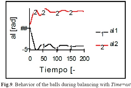
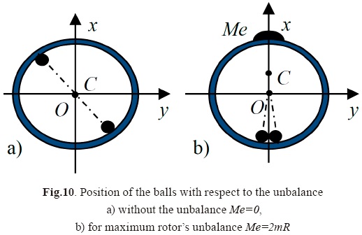
The balls start from any initial positions and, under the action of vibratory forces, go to the final positions in which they compensate rotor unbalance and eliminate vibration. Fig.10 presents the position of two balls for two different unbalance of the rotor. If there is no unbalance then the balls occupy the position of the same diameter-Fig.9a.
If the rotor has some degrees of freedom, then each component of vibrations generates a vibratory force. So, for rotors with two degrees of freedom with components vibrations x(t) and y(t), the vibratory force is

where Fix is a component force of the vibration x(t) and Fiy of vibration y(t) [9].
Balancing a Washing Machine
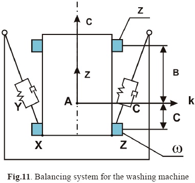
This method of balancing is especially suitable for washing machines and centrifuges where the unbalance changes with every use and also during the extraction of water from clothes. The free elements (balls, rollers or liquid) can be located in one or two rings - Fig.11. A rotating basket with one ring is only able to compensate static unbalance and a basket with two rings can compensate both static and dynamic unbalance [10, 11].
The principle of self-balancing can be presented as is shown in Fig.12. Vibrations generate the vibratory forces and they push the balls to new positions in which they compensate for the rotor's unbalance.
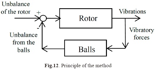
In a self-balancing system there is one frequency and only the angle between the ball and unbalance changes - phase synchronization.
Dynamic Eliminator of Vibrations
If the balls are able to compensate the excitation from the rotor's unbalance then they should also compensate any excitation [12 - 15], e.g. from the base vibration z(t)=zosin(Ωt) - Fig.13. The rotating drum with free balls is mounted on an object which is separated from the vibrating base by a viscous-elastic element. The frequency of excitation is Ω and the spin velocity of the drum is ω.
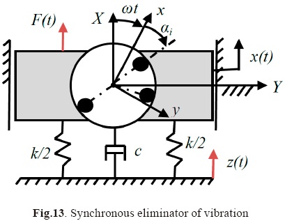
The behavior of the object and the balls is governed by the following equations
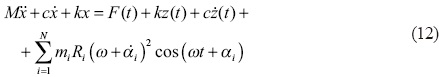

For a synchronous motion of the balls their position with respect to the rotor changes as

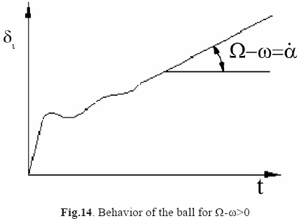
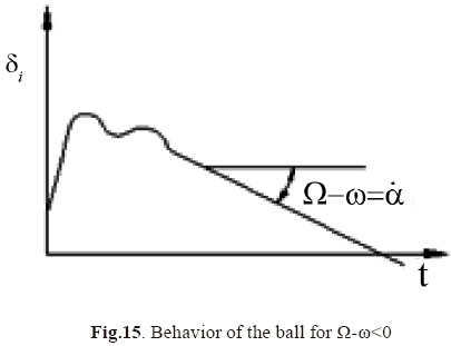
The vibratory force is defined by an equation similar to Eq.8. The ball starts to move with respect to the drum with velocity Ω-ω and goes to the position opposite the object's excitation, as such they eliminate the object's vibration. The behavior of one ball is presented in Fig.14 and Fig.15.
The behavior of the system with two balls is shown in Fig. 16.
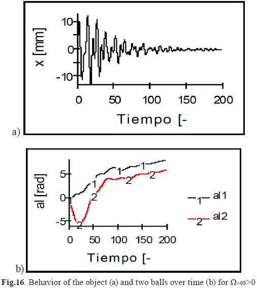
If the difference between two spin velocities Ω-ω is great, th. en the balls do not move synchronously with excitation 0  and they occupy positions in which they compensate each other (Fig.10a) - the balls do not eliminate vibrations but also do not increase them.
Dynamic Eliminators of Vibrations for Complex Systems
The method can be applied to a more complicated system in which many objects are connected by viscous-elastic elements, as shown in Fig.17. Each object has two free elements as pendulums. The harmonic excitation can enter at any point of the system. It is interesting that such a system can organize itself and compensate the excitation. It was shown that depending on the amplitude of the excited force it can be compensated by the free elements of the first object or for greater excitation a part of it is compensated by the first object and the rest of excitation is compensated by neighbor objects [14]. The motion of ijth object in X direction and its pendulums is governed by equations (15)
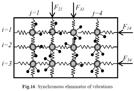
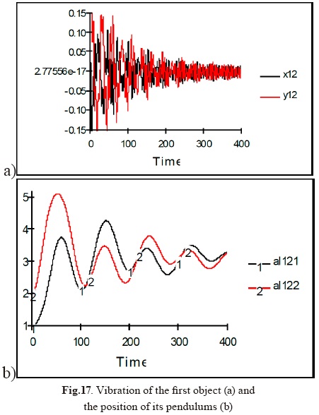
Fig.17 presents the behavior of the first object with its free elements which are not able to compensate for the excitation (Foij>2mRω2). Fig.18 presents the neighboring object which compensates for the rest of the excitation.
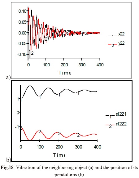
The greater the magnitude of the excitation, the deeper it enters into the system.
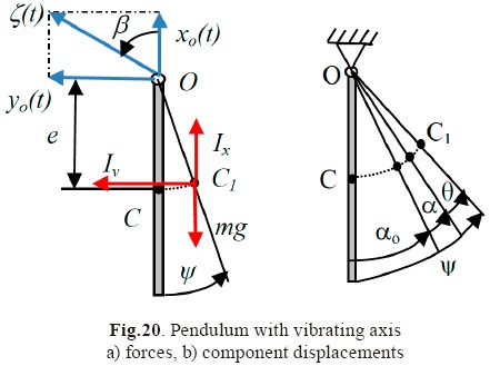
Pendulum with Vibrating Pivot
A lower equilibrium position of the pendulum becomes unstable and the upper position (inverse position) may be stable with a vibrating axis of rotation O [16]. Stability depends on the magnitude and frequency of the axis' vibrations ξ(t) - Fig.20.
If the axis O vibrates vertically in a harmonic way with amplitude A then the motion of the pendulum is defined by the Mathieu's equation

where the coefficients a and q depend on the system parameters.

J is a mass moment of the pendulum's inertia.
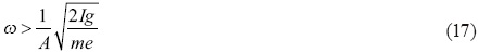
The lower position of the pendulum is unstable for a=1 and inverse position is stable for the frequency of excitation
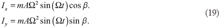
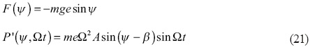
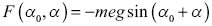
This behavior can be explained using vibratory forces. The vibration of the pendulum's pin is taken to be harmonic with a direction defined by the angle β.

As a result of vibration there are inertial forces
A small vibration of the pendulum with respect to its position of equilibrium defines the equation

where
The force F(ψ) changes slowly in time but the force Q'(ψ, Ωt) depends on the frequency Ω and changes very quickly in time. They have different influences on the behavior of the pendulum. A slowly changing force F(ψ) generates a displacement αo+α(t) while a fast force P'(ψ, Ωt) generates vibration θ(Ωt). The solution of Eq. (15) can be presented as

where
αo - defines the position of equilibrium,
a(t) - slow vibration,
Θ(Ωt) - fast vibration.
Each competent of vibration is defined by the following equations

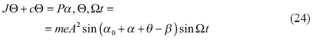
where 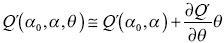
For 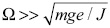 the solution of (19) has the form

where θ0 ≅ meA / J .
The amplitude of fast vibration depends on θo, direction of the pivot's vibration β and the position of the pendulum's equilibrium αo.

The influence of the fast vibration on the slow vibration can
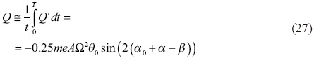
It is a vibratory moment generated by fast vibration θ(Ωt).
The resultant vibratory W moment for slow vibration consists of the moment from the gravitational force F(αo, α) and the fast vibration Q(αo, α, β).

where
At the equilibrium position of the pendulum the resultant moment is zero

The position of equilibrium ao defines the equation (29) and it depends on the frequency Ω, amplitude of pivot's vibration A, and its direction β.
Fig. 21 presents the behavior of the pendulum at its lower position when the frequency of excitation is close to the frequency of parametric resonance.
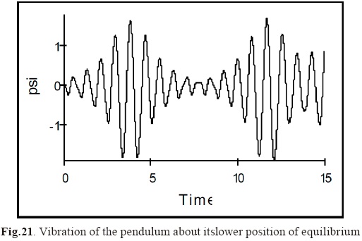
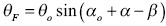
Fig. 22 presents the behavior of the pendulum with respect to its upper stable position αo= 4 rad. For the angle β=0 the amplitude of fast vibration is zero and for β≠0 the amplitude of fast vibration is
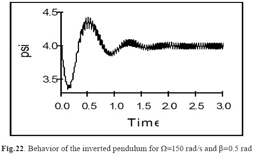
The vibratory moment is responsible for the equilibrium position of the pendulum and the frequency of its free vibration.
The change of vibratory moment when the pendulum changes its position a with respect to the position of equilibrium ao is shown in Fig.23.

Vibratory forces can change the properties of the pendulum. The static lower equilibrium may become unstable and the unstable upper position may become dynamically stable due to vibratory forces.
Vibratory Transport
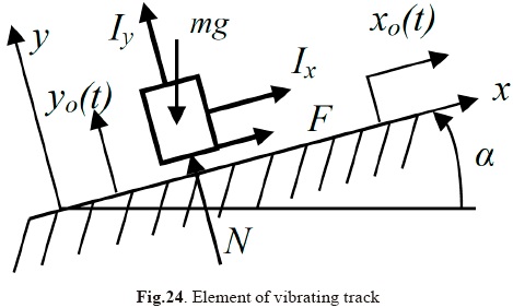
Vibration of the plane can generate continuous motion of the elements which are on it. This is vibratory transport [17]. The vibration of the plane generates vibratory forces Ix, Iy that push an element - Fig. 24. Direction and velocity of the element are functions of the components of vibration of the plane, their amplitude and their frequency.
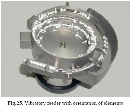
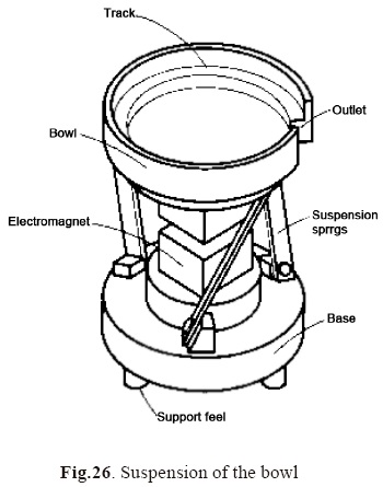
This kind of transport is popular for ensemble line of small elements and the vibratory feeder is used - Fig.25. The track of the feeder has to have a component of vibration perpendicular to the track and another tangent to the track. To obtain these vibrations with one excitation force the bowl is suspended on three inclined flat springs as shown in Fig. 26.
The vibratory forces can also be used to decrease friction force (e.g. in bearings) [22].
Vibromotors
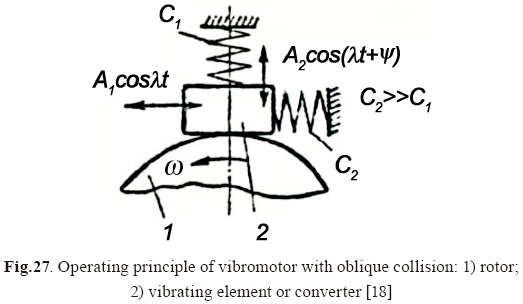
Vibromotors are used in mechatronics and robotics for very small and exact linear or angular displacement [18]. A vi-bromotor is a mechanism which converts high frequency vibrations into a continuous or stepping motion.
The vibratory motion is imparted to the member using a magnetostrictive or piezoelectric converter. Contact between these and a friction force generates continuous motion.
Fig.27 presents a vibromotor with oblique collisions. A two-coordinate motion of the vibrating member defines the normal and the tangential components of the impact velocity.
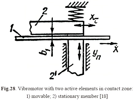
In the other solution (Fig.28) there are two active elements in the contact zone and the normal and tangential components of the impact velocity are formed by separate converters.
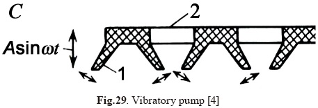
Vibratory pumps have very similar principles of action.
Vibratory Finishing
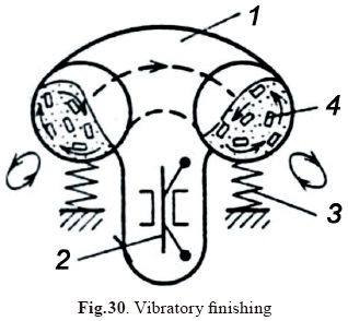
In vibratory finishing (Fig.30) (29), a container vibrates with small elements inside abrasive material. The vibratory forces push the elements and they oscillate with respect to the abrasive material. The friction force and small impacts between the elements result in finishing their surfaces. Vibratory finishing is widely used in a large-scale production for debarring, rounding and brightening elements [19].
Other Mechanical Examples where Vibratory Forces and Synchronization Apper
Vibratory rammer or sledge
The motor of the rammer generates vibration of one part and when it rams down it packs soil while the rammer slowly moves forward [20].
Vibratory mole - inside a mechanical mole there is a vibration generator and the mole generates higher force in one direction than the other and it allows making tunnels in earth.
It is well-known that with vibrations the friction force decreases and dry friction changes into viscous friction [21-22].
In acoustics it is observed that two pipe organs with close frequencies can produce sound in unison or mute each other.
Synchroniation in Nature
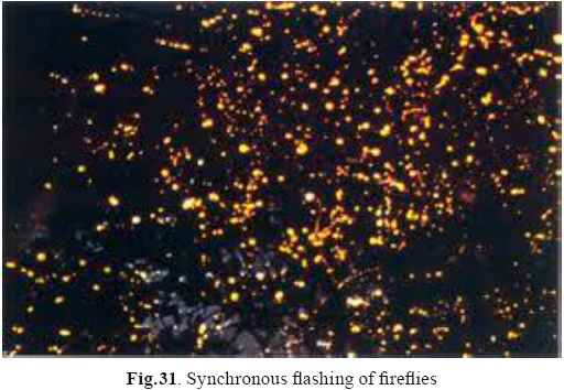
An interesting example of synchronization in nature is the behavior of Asian firelies. At dusk, the flies begin to flash at random. As night falls, the flies begin to synchronize their flashing. After some time all the fireflies within an area begin to flash in unison. Between them there are some constrains through which a periodic signal is transmitted. There are other type of "vibratory forces" between flies. As they begin to flash simultaneously they become synchronized in phase.
Initially audience applause is random but after some time clapping and stomping comes to occur in unison. Groups of soldiers also march in unison.
Synchronization is a kind of selforganization in some systems. The elements of the system influence each other and make a specific arrangement in their behavior. Some examples were given in this paper (automatic balancing or dynamic elimination of vibrations) but such examples can be found in any system (e.g, biology, social systems, etc.).
Neural oscillations refer to rhythmic or repetitive neural activity in the central nervous system. Synchronization of neuron activity is the main mechanism here. The frequency of the operation of organs is controlled by various forms of central memory organized in the neural system. Neural activity often oscillates at specific frequencies or frequency bands. The most well-known frequency band is alpha activity (8-12 Hz). Neural oscillations may have different functional roles in different brain areas. The system is healthy as long as it communicates properly and the subsystems perform their operations at the right moments in time.
The self-organization of different systems can be observed from atoms or cells to the cosmos.
If telepathy really exists it could be explained by transmission of waves from one person to another. If they work on similar frequencies to those of the other person, they may obtain sufficiently strong signals to decode this information.
Conclusions
It has been shown that in mechanical systems vibratory forces exist which can account for special behavior; synchronous motion (unison motion with the same or opposite phase), it is possible to transmit power from one rotor to another without direct connection, automatic compensation of dynamic forces. In other physical systems weak constraints also exist between objects which result in their synchronization.
References
[1] Christiaan Huygens, Letter to the Royal Society of London, 1673. [ Links ]
[2] I.I. Blekhman, Synchronization of Mechanical Systems (in Russian), Nauka 1971, Moscu. [ Links ]
[3] I.I. Blekhman, What can do vibrations (in Russian), Nauka, Moscou 1988. [ Links ]
[4] I.I. Blekhman, Vibrational Mechanics, Nonlinear Dynamic Effects. World Scientic, 2000, Singapore. [ Links ]
[5] W. Bogusz, Z. Engel. Investigation of a system for con-tactless transmission of power (in Polish). Science-technical information, HPR 20, 1965. [ Links ]
[6] W. Bogusz, Z. Engel. Experimental investigation of self-synchronization systems. Overview of Mechanical Engineering (in Polish), 1965, No.8, pp.230-232. [ Links ]
[7] T. Majewski, R. Domagalski, M. Meraz. Dynamic compensation of dynamic forces in two planes for the rigid rotor. Journal of Theoretical and Applied Mechanics, No 2, Vol. 45, 2007, pp.379 - 403. [ Links ]
[8] T. Majewski, D. Szwedowicz, A. Herrera, Automatic elimination of vibrations for a centrifuge. Mechanism and Machine Theory, Volume 46(3), March 2011, pp.344-357. [ Links ]
[9] L. Sperling, B. Ryzhik, Ch. Linz, H. Duckstein, Simulation of two-plane automatic balancing of a rigid a rotor, Mathematics and Computers in Simulation, Vol.58, Issues 4-6, 2002. [ Links ]
[10] T. Majewski, Compensation system of the dynamic forces in the clothes washer, XVI Congreso Internacional Anual de la SOMIM, 2010, Monterey. [ Links ]
[11] T. Majewski, I. Valenzuela, Fluid automatic balancer for a washing machine, XVI Congreso Internacional Anual de la SOMIM, 2010, Monterey. [ Links ]
[12] T. Majewski, Synchronous vibration eliminator for an object having one degree of freedom, Journal of Sound and Vibration, 112(3), 1987, pp.401 - 413. [ Links ]
[13] T. Majewski, Synchronous vibration elimination in the plane. Journal of Sound and Vibration, 232(2), 2000, pp.553-570, pp.571-584. [ Links ]
[14] T. Majewski, Synchronous Eliminator of Vibration in 3-D, 14th US National Congress of Theoretical and Applied Mechanics, June 23-28, 2002, Blacksburg, USA. [ Links ]
[15] T. Majewski, The properties of a dynamic eliminator for a car's vibrations, Mechanism and Machine Theory, 45 (10), (2010) , pp.1449-1461. [ Links ]
[16] T. Majewski, R. Sokolowska, Vibrational mechanics for the pendulum with oscillating pivot, International Conference MECHATRONICS2004, Warsaw, Poland, 2004, pp.187-190. [ Links ]
[17] T. Majewski, O. Paleta, Modelado de movimiento vibratorio. Computación Aplicada a la Industria de Procesos CAIP2003, pp.337 -340, UDLA, 2003. [ Links ]
[18] K. Ragulskis, R. Bansevicius, R. Barauskas, G. Kul-vietis, Vibromotors for Precision Microrobots, Hemisphere Publishing Corporation, New York 1998. [ Links ]
[19] T. Majewski, R. Sokolowska, Analysis of viscous-elastic model in vibratory processing, Springer Berlin Heidelberg New York, 2007, pp.490-494. [ Links ]
[20] T. Majewski, R. Bravo. Análisis de una compactado-ra de placa vibratoria, Congreso Internacional Anual de la SOMIM, Puebla, 2008. [ Links ]
[21] T. Majewski, J. Saenz, R. Sokolowska. Friction between a body with an elastic layer and vibrating plane. Machine Dynamics Problems 2006, vol.30, No.2, pp. 103.-112. [ Links ]
[22] T. Majewski, Resultant friction for a system with vibration. Machine Dynamics Problems 2008, Vol.32, No.2, pp. 38 - 48. [ Links ]

