


Servicios Personalizados
Revista
Articulo
 Inglés (pdf)
 Artículo en XML
 Referencias del artículo
 Enviar artículo por email
Indicadores
-
 Citado por SciELO
 -
 Accesos
Links relacionados
-
 Similares en
SciELO
Similares en
SciELO
Compartir

 Permalink
Ingeniería mecánica, tecnología y desarrollo
versión impresa ISSN 1665-7381
Ingenier. mecáni. tecnolog. desarroll vol.2 no.6 México mar. 2008
Artículos
Optimal Design of Stockbridge Dampers
Celia Navarro Canales, Arturo Lara López, José Colín Venegas, Jesús Razo-García, and Luz A. Aguilera-Cortés
Faculty of Mechanical and Electrical Engineering University of Guanajuato.
Fecha de recepción: 25-10-07
Fecha de aceptación: 10-01-08
Abstract
Stockbridge dampers are devices extensively used to reduce vibration amplitude on electric lines due to wind, avoiding the risk of fatigue on the line. Acceptable performance of dampers must be maintained for a wide range of excitation frequencies, which have a correspondence with the wind velocity. In this paper a formal approach for optimizing Stockbridge dampers parameters is proposed. In one case, optimal damper parameters are calculated for maximum vibration attenuation as the objective, and in a second case, such parameters are determined for a minimum cost of the damper materials as the goal. In both cases, infl uences of dynamic parameters of dampers on the defi ned objective function are determined. Dynamic response of a conductor strand with a damper attached is iteratively calculated by means of an optimization procedure applying finite element method. Analysis of the influence of parameters led to a simplified optimization model reducing the problem to a regular optimization analysis.
Keywords: Optimization of Stockbridge dampers, Optimal design.
Resumen
Los amortiguadores tipo Stockbridge son dispositivos que se han usado ampliamente en líneas eléctricas para reducir la amplitud de vibración causada por el viento, evitando con esto el riesgo de fatiga en la línea. Los amortiguadores deben mantener un desempeño aceptable para un rango amplio de frecuencias de excitación, las cuales tienen una correspondencia directa con la velocidad del viento. En este artículo se presentan dos metodologías para la optimación de los parámetros de este tipo de amortiguadores. En un primer caso, los parámetros del amortiguador se determinan de tal manera que la atenuación de la vibración sea máxima, mientras que en el segundo caso, dichos parámetros se determinan para minimizar su costo. En ambos casos se analiza la influencia que los parámetros tienen en la función objetivo. Adicionalmente, la respuesta dinámica de un tramo de línea con su amortiguador se evalúa de manera iterativa con un procedimiento de optimación aplicando la técnica de elemento finito. El análisis de la influencia de los parámetros conlleva a un modelo simplificado sobre el que se aplica un análisis de optimación no lineal.
Palabras Clave: Optimización de amortiguadores Stockbridge, diseño optimo.
Introducction
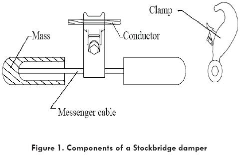
Since 1924, when G. H. Stockbridge patented the damper that now carries his name, these mechanical devices have been modifi ed a number of times to improve their performance. Such dampers have two masses attached to the ends of a strand cable, called the messenger cable, which is supported from the middle by a clamp rigidly assembled to the electric line, Fig. 1. The function of this type of dampers is to dissipate mechanical energy from the electrical conductor as heat caused by friction between wires of the messenger cable. The purpose of such effect is to reduce the vibration amplitude of the electric conductor protecting it from mechanical fatigue. Vibration frequency of electric conductors is directly related to wind speed, [1]. Dampers must have suffi cient dissipation capability for the interval of wind speed expected in the field. In addition, dampers must resist the reversing stresses on wires of messenger cable. Optimization of a damper from the point of view of its performance includes the definition of an objective function in terms of attenuation (reduction of conductor vibration amplitude) for the expected interval of vibration frequencies. A natural constraint in the optimization of a damper is the requirement for the messenger cable to endure the reversing stresses for a large number of cycles.
A second criterion to optimize the dampers is to minimize the cost of manufacturing materials. In this case, a constraint to insure a sufficient capacity to reduce the conductor vibration amplitude needs to be included, in addition to the constraintrelated to endurance.
Analysis of the response of conductors with assembled dampers is necessary for the optimization process. Many authors have signifi catively contributed to the understanding and analysis of conductor dynamic response. Claren and Diana [2] reported an analytical method to determine the response of a conductor span with dampers and local exciting force. In addition, these authors analysed the response of dampers alone and presented an experimental method to determine the dynamic parameters of dampers. Rawlins [3,4] reported a comprehensive discussion on the main concepts on vibration of transmission lines including the theoretical development of the method of nodes and antinodes to evaluate effi ciency of dampers. It is commonly accepted that the Stockbridge dampers cause a reduction in the amplitude of aeolian vibration because of their dissipative power. Feldmann [5], mentioned that the non-linear behaviour in this type of damper explains its high efficiency. Unfortunately, these non-linearities have been examined with little success because of theoretical and experimental diffi culties. Graphic methods have been employed in practical cases due to their simplicity. Most recently, an analysis for the capacity of dampers for energy dissipation has been reported by Richardson [6], who presents a simple method to determine if the dampers are needed and to calculate how much damping is required. The method compares the wind energy input and conductor energy loss and the difference between both represents an energy shortfall that must be supplied by dampers. Hence, this shortfall becomes a performance requirement for the damper. Hagedorn [7] proposed a method to determine optimal parameters of dampers for a maximum dissipation of energy. However, no practical constraints were incorporated to limit the damper mass to acceptable values. Markiewics [8] presented an optimization analysis of Stockbridge dampers for dead-end spans. The author shows that the optimum damper for such spans differs significantly from a commercial damper. The purpose of this paper is to propose a general optimization method for Stockbridge dampers, where an objective function may be defined according to the particular goal of a designer, which may be subjected to specifi c design constraints. In particular, the cases for maximum attenuation (reduction of amplitude vibration) and minimum cost of materials as objective functions are presented.
Vibration of lines with dampers
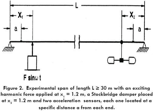
The physical system often used to evaluate the attenuation capacity of a damper includes a span of a stranded conductor larger than 30 m under a tension of a quarter of its ultimate strength, being excited by an harmonic force located close to one end of the conductor and a Stockbridge damper close to the opposite end of the same conductor, Fig. 2.
Several authors referenced above analytically predicted the dynamic response of this type of continuous system. With the present availability of finite element computer programs, a discrete model was considered to facilitate the determination of the response of such a physical system, [9], Fig. 3.
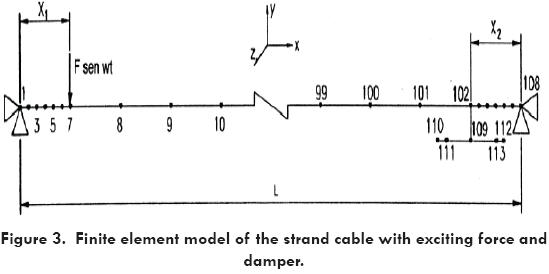
The finite element model of the cable was made using cable type elements [10], connected by nodes 1-2, 2-3 and so on through 107-108. In addition, two beam elements (connected by nodes 109-110 and 109-112) and two mass elements (at nodes 111 and 113) are used in the finite element model to simulate the damper.
Boundary conditions for the finite element model are defined as:
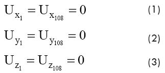
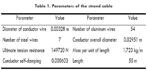
Where, Ux, Uy and Uz are respectively the displacements in X, Y and Z direction for nodes 1 and 108. Table 1 shows the parameters of the system that define the properties of the finite element model.
To compare the improvement of the system when a damper is used, the natural frequencies and the corresponding amplitude of vibration at the point in the system where the sensor is located were calculated for both cases (with and without damper) and are reported in Table 2.
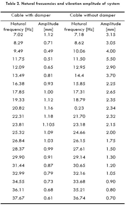
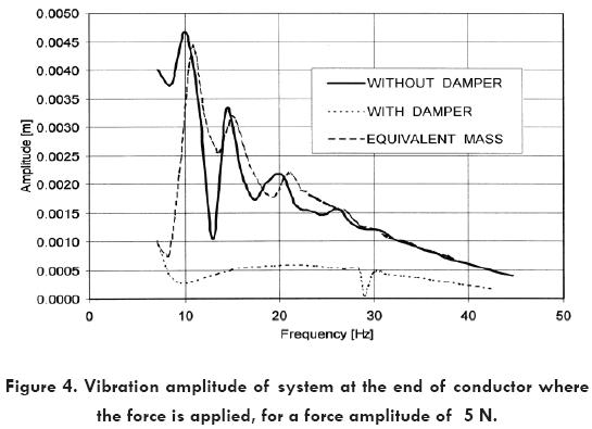
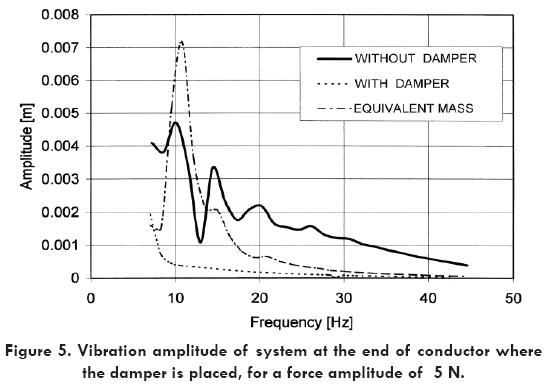
It can be observed that from 7 to 25 Hz the vibration amplitude is reduced by the use of a damper in the cable. This reduction is in the range from 80 to 90 percent evaluated on the point where the transducer is located. To show this, the vibration amplitude at both sides of the conductor (damping and no damping) is plotted against the frequency for all the vibration range. Figures 4 and 5 show the conductor vibration amplitude at nodes 4 and 105, representing the points in the system where the sensors are located at the no damping side and at the damping side respectively, for the following three cases: a) when a damper is used, b) when no damper is used, and c) when an equivalent concentrated mass is used instead of the damper. From these fi gures it can be observed the effect on the reduction in the vibration amplitude of the system with the use of a damper. However a concentrated mass (dynamically equivalent to the mass of the damper), does not affect the vibration amplitude of the system beyond frequencies in the range from 7 to 13 Hz (near the fi rst natural frequency of the system).
A criterion that have been applied to evaluate the performance of dampers for all the range of vibration frequencies is the average or mean value of the attenuation V evaluated at points on the cable where the transducers are located (see Fig 2). The attenuation is defined as function of the amplitude of vibration of the cable Y, by the following equations:
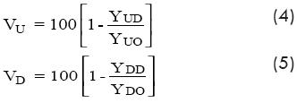
Where, the subindex in V and the first subindex in Y are related to the location of the transducer, at the damping side (D) or at the no damping side (U), while the second subindex in Y refers to the presence (D) or absence (O) of the damper. It is required that the average value of the attenuation, called efficiency, for both acceleration transducers be greater than 80 percent.
Vibration of dampers
Endurance of dampers is evaluated by exciting a sample of a lot of commercial dampers on a vibration table. The excitation frequency f [Hz] should be the first natural frequency of the damper and the amplitude of excitation Ua is given by Eq. 8. In order for a damper to be accepted it is required to endure 107 cycles, under the above described conditions, [11].
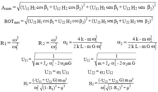
Acceleration transducers are located at the center of mass of the damper and on the vibration table. Signals from such transducers are used to determine the self-damping coefficient for the messenger cable. For this purpose the damper is assumed as a discrete system with two degrees of freedom, which natural frequencies ω (rad/s) may be experimentally found or calculated by the following equation, [2].
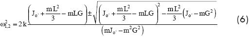
Where k and L are the stiffness and length of messenger cable respectively, Jo' is the mass moment of inertia about the point of contact O' between the messenger cable and the mass, G is the distance from point O' to the center of mass of the damper O and m is the mass of one of the damper weights.
The stress on the messenger cable was calculated in terms of the dynamic response of the damper, considering the deflection of one single wire, which was analysed as a cantilever beam. An expression for the calculation of the bending stress σ on a single wire is the following, [12].
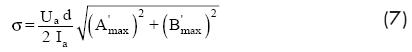
where d is the diameter of a single wire of the messenger cable, and:
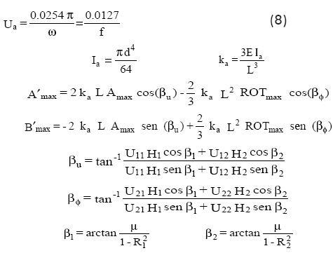
where µ is the damping coefficient for the messenger cable, and
Optimization procedure
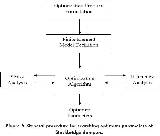
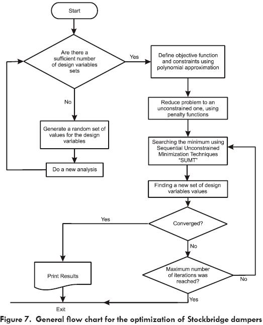
An optimization algorithm was incorporated into the fi nite element code [10] in order to search for an optimum following a defined optimization technique. Among the most popular optimization techniques are zero and fi rst order methods. However calculation of the objective function and its derivatives for each point into the design region is not performed directly. It is necessary to calculate the response of the system for each one of its natural frequencies for each set of the design variables along the optimization procedure. Then, the objective function and constraints for the problem are calculated and a search direction is defi ned looking for the optimum. For the particular case of optimization of Stockbridge dampers, Figs. 6 and 7 show a general fl ow chart for the optimization procedure.
Optimization for Maximum Attenuation
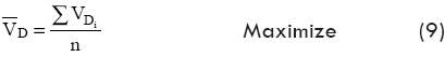
As was mentioned previously, the mean attenuation or efficiency of a damper is required to be greater than 80 percent when the system of Fig. 2 is excited to each one of its first n natural frequencies in the range of locally expected winds. Based on this criterion the optimization problem will be to maximize the efficiency (mean attenuation) at the damping side, then the objective function may be defined as [13]:
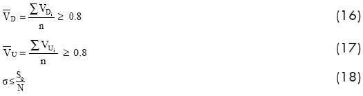
Subject to inequality constraints related to the mean attenuation of the cable at the no damping side, and the endurance stress due to fatigue of the messenger cable. The first constraint may be defined as:

In order to meet the endurance requirement mentioned above it is necessary to keep the stresses of a wire lower than its endurance then, the second constraint may be defined as:
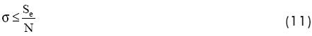
where:
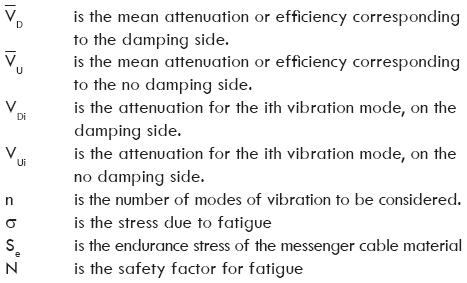
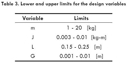
The design variables selected for the optimization analysis, all related to the damper, are: the mass m, its moment of inertia respect to the center of mass J, the length of the messenger cable L and the location of the center of mass related to the point of contact of the messenger cable and weight G. Table 3, shows the interval for each variable.
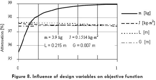
It was of especial interest to explore the influence of each design variable on the objective function. To do that, the objective function was calculated for several values of one of the four design variables maintaining the other three as constant. Fig. 8 shows the effect of each variable on the objective function for the particular case of a commercial cable. It is evident that mass is the most important variable followed by the length of the messenger cable. The influence of the moment of inertia J and the location of center of gravity G are small for the interval considered. In order to facilitate the interpretation of the objective function and constraints within the design area, a second set of optimization runs considering only mass and length as design variables, was done. For the interval of these variables, the objective function and constraints were calculated for a fine mesh and then the following nonlinear regressions were determined:
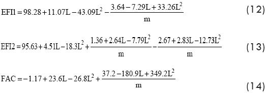
where:
EFI1 is the efficiency of the damping side.
EFI2 is the efficiency of the no damping side.
FAC is the safety factor N.
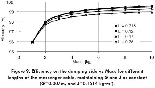
Parametric representation of these equations is shown in Fig. 9. It can be seen from this graphic that an increment of mass contributes to increase the attenuation. However, after a certain value of mass, the corresponding increment on attenuation is not important. On the other hand an increment in the mass reduces the safety factor drastically.
It is important to mention that once equations (12), (13) and (14) are determined the optimization problem is reduced to a regular one, being possible to apply common optimization algorithms for multivariable constrained problems, or sequential unconstrained minimization algorithms, [14].
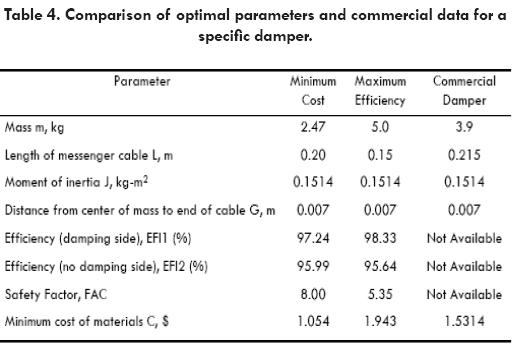
The optimal parameters of the damper for maximum efficiency and the corresponding average efficiency in both ends of the conductor are presented in Table 4.
Optimization for Minimun Cost
A second approach to the problem is to minimize the cost of materials and still meet the design requirements. In this case the objective function may be defi ned as:

Subject to constraints related to the mean attenuation of the cable at both (damping and no damping) sides, and the endurance stress due to fatigue of the messenger cable. These inequality constraints are defined as follows:
where:
Cc is the unit cost of messenger cable
Cm is the unit cost of material for the mass
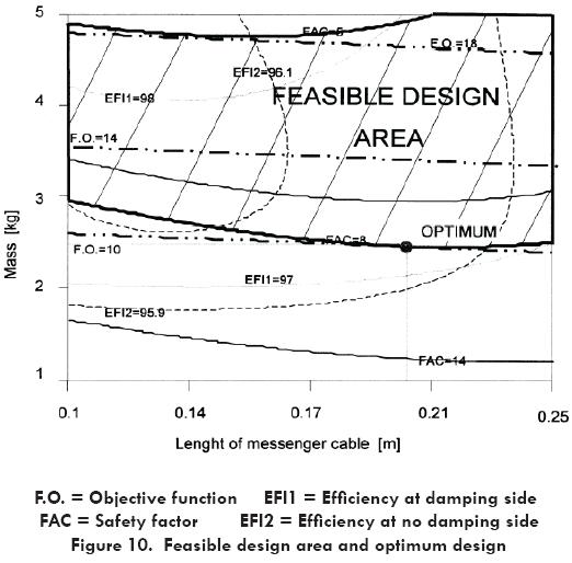
Then, the solution was obtained substituting equations (12), (13) and (14) in the constraint equations. For the case of two design variables (mass m and length of messenger cable L) the feasible design area and the optimum solution are shown in Fig. 10.
Finally, Table 4 presents the optimum values for the design variables and parameters of the Stockbridge damper obtained from the optimization process, and their comparison with commercial parameter data.
Discussion and Conclusions
The proposed optimization procedure permits to select the objective function of greatest interest for the designer of Stockbridge dampers. From the analysis previously presented, the following conclusions may be noted:
1. Vibration attenuation is mainly influenced by mass of the damper weight, according to a continuously growing relation. However, the rate of growing of attenuation decreases as the mass increases. This situation suggests the establishment of an interval for the mass to maintain this variable into practical values.
2. The relationship between the safety factor and fatigue of the messenger cable decreases continuously with the increment of mass of damper. This is in fact a reason to limit the maximum value of the mass.
3. The length of messenger cable is the second most important variable influencing attenuation. Up to certain limit, the shortest value of the length produced the highest attenuation.
4. The safety factor showed a decreasing variation with the length of messenger cable, within the limits established for the analysis.
5. The finite element method is an efficient tool in the optimization of dampers and in the analysis of infl uence of variables, making it possible to explore parameter within the design area.
Acknowledgements
Authors are indebted with The University of Guanajuato thru the Faculty of Mechanical and Electrical Engineering at Salamanca, México for the continuous support to this research. Equally relevant was the support from the Laboratory for Test of Equipment and Materials of the Federal Electricity Commission (CFE) at Irapuato, México. Careful revision of the research results and valuable suggestions from Dr. Ricardo Chicurel Uziel were of much help in the solution of the modelling and optimization analysis.
References
1.- EPRI, 1979. "Wind-Induced Conductor Motion," Transmission Line Reference Book, Electric Power Research Institute, Palo Alto, CA. [ Links ]
2.- Claren, R. and Diana, G.,1969, "Mathematical Analysis of Transmission Line Vibration," IEEE Transactions on Power Apparatus and Systems, 88(12), pp. 1741-1771. [ Links ]
3.- Rawlins, C. B., 1988, "Research on Vibration of Overhead Ground Wires," IEEE Transactions on Power Delivery, pp. 769 - 775.
4.- Rawlins, C. B., 1981, "Recent Developments in Conductor Vibration Research," Alcoa Research Laboratories, Technical Paper No. 13. [ Links ]
5.- Feldmann, D., 1988, "Aeolian Vibrations: Possible Effects of Non Linear Behaviour of Stockbridge Dampers," IEE Conference Publication 297, London UK, pp. 70-74. [ Links ]
6.- Richardson, A. S., 1996, "Performance Requirements for Vibration Dampers," Electric Power Research, 36, pp. 21- 28. [ Links ]
7.- Hagedorn, P., 1982, "On the Computations of Dampers Wind-Excited Vibrations of Overhead Transmission Lines," Journal of Sound and Vibration, pp. 252-271. [ Links ]
8.- Markiewics, M.,1995, "Optimum Dynamic Characteristics of Stockbridge Dampers for Dead-end Spans," Journal of Sound and Vibration, pp. 243-256. [ Links ]
9.- Aguilera-Cortés, L. A., 1995, "Analysis and Simulation of Vibrations in Transmission Lines to Determine the Efficiency of Eolian Vibration Dampers," PhD Thesis, University of Guanajuato, Mexico. [ Links ]
10.- Swanson Analysis Systems, 1997, "ANSYS: Engineering Analysis PC/Linear revision 5.2," Houston TX. [ Links ]
11.- Comision Federal de Electricidad (CFE), 1994, "Stockbridge Dampers for Transmission Lines," Standard CFE 511BO-36, México. [ Links ]
12.- Lara-López, A. and Colín-Venegas, J., 2001, "Endurance of Dampers for Electric Conductors," International Journal of Fatigue, 23, pp. 21-28. [ Links ]
13.- Navarro-Canales C., 2000, "Optimization of Stockbridge Dampers," PhD Thesis, University of Guanajuato, México. [ Links ]
14.- Kuester, J. L. and Mize, J. H., 1973, "Optimization Techniques with Fortran," McGraw-Hill Book Company, Chapter 10, pp 367-497. [ Links ]

