SciELO - Scientific Electronic Library Online

 
vol.20 número6A semantic framework based on domain knowledge for opinion mining of drug reviewsInvestigation of the thermal behavior of water flow within parallel tubes in a solar collector índice de autoresíndice de materiabúsqueda de artículos
Home Pagelista alfabética de revistas  

Servicios Personalizados

Revista

Articulo

Indicadores

Links relacionados

  • No hay artículos similaresSimilares en SciELO

Compartir


Journal of applied research and technology

versión On-line ISSN 2448-6736versión impresa ISSN 1665-6423

J. appl. res. technol vol.20 no.6 Ciudad de México dic. 2022  Epub 08-Mayo-2023

https://doi.org/10.22201/icat.24486736e.2022.20.6.1800 

Articles

Angular error reduction of a machine-vision system using a trapezoidal trajectory velocity

Lars Lindnera 

Julio C. Rodríguez-Quiñonezb 

Wendy Flores-Fuentesb 

Oleg Sergiyenkoa 

Fabian N. Murrieta-Ricoc  * 

a Universidad Autónoma de Baja California, Instituto de Ingeniería, Mexicali, Baja California, México

b Universidad Autónoma de Baja California, Facultad de Ingeniería Mexicali, Mexicali, Baja California, México

c Universidad Politécnica de Baja California, Ingeniería Mecatrónica, Mexicali, Baja California, México


Abstract

Nowadays, laser scanners play an important role in technology and research, when it comes to measure 3D coordinates physically and in real time of any object under observation. Laser scanners have to measure the 3D coordinates of these objects in shortest time and with the smallest measuring error. A novel laser scanner called Technical Vision System (TVS), which uses Dynamic Triangulation and DC motors, was developed and proven to represent a fast and reliable scanning system. Previous research used the step response of the TVS mechanical actuators (DC motors), which can overshoot if certain controller parameters of the closed-loop control are selected. If the overshoot is undesirable, a trade-off must be made between speed and overshoot of the step response. Thereby, present paper describes a new approach to control the actual angular position of the TVS DC motors using a trapezoidal profile for the DC Motor velocity. The DC motors step response is replaced by a trajectory response, which allows the reduction of the relative angular error of the DC motors shaft to a value less than or equal to 0.1 percent. Also, the design of the control system, to implement the trapezoidal trajectory profile for the DC motor velocity in practice, is described in detail.

Keywords: Absolute position error; DC motor; digital controller; machine vision system; trapezoidal trajectory velocity profile

1. Introduction

Laser scanners as sensors in machine vision systems play an important role, when it comes to measure three dimensional coordinates of any object under observation. Compared to other types of sensors, laser scanners offer advantages, because they do not estimate the 3D data of these objects, but determine their physical position and in real time using different measurement methods (Sergiyenko & Rodriguez-Quiñonez, 2016). Thereby, laser scanners capture stereo data of the scanning object without having to compare between different scanning points, as is the case with cameras, for example. This allows to design laser scanners as single sensor systems, with low requirements of data post-processing. However, most laser scanners today still use cameras to receive the reflected laser beam and convert it into a matrix of digital signal values. Compared to single-sensor photodetectors, cameras have significant disadvantages, which can be defined using the precision of real physical values measurement and the speed of post-processing of these values. The main task of laser scanners can be defined by the determination of observed objects 3D coordinates, which is mainly realized using optical methods in a very large number of applications. 3D mapping (Zhang & Singh, 2017), autonomous robots, automatic inspections, coat thickness measurement, object existence and location detection, show clear examples of accurate positioning technologies. Besides, most of those are constituted using mechatronics systems, which integrate DC motors as main electromechanical actuators. A novel Technical Vision System (TVS, prototype No.3) was developed (Lindner, Sergiyenko, Rivas-López, Hernández-Balbuena, et al., 2017), which represents an optoelectronic machine vision system capable of measuring 3D coordinates in the TVS field-of-view (FOV), to determine the information of scanned surfaces for scientific and industrial applications. The TVS has the key advantage over cameras that it is basically designed and constructed as a single-sensor, high-speed, and ultra-low cost laser scanning system, which uses the dynamic triangulation measurement method and trigonometric functions, to measure 3D coordinates of any object under observation (Lindner, Sergiyenko, Rodríguez-Quiñonez, et al., 2016; Lindner, Sergiyenko, Rivas-López, Ivanov, et al., 2017). Dynamic triangulation, in comparison to classic (static) triangulation, allows a faster acquisition of all 3D coordinates in the FOV of a laser scanner. Since with dynamic triangulation only the laser point is moved over the surface of an object under observation, and not the entire technical system, higher dynamics and thus significantly reduced scanning time can be achieved. A typical application for dynamic triangulation can be found in the navigation of mobile vehicles, where fast acquisition of 3D coordinates plays an important role. Using the novel approach of dynamic triangulation and the TVS, the mobile vehicle FOV can be defined regardless of its movement trajectory, and thus the vehicle can map and capture a new environment in shorter time and with less energy usage, than with static triangulation or multiple sensor systems. When designing this TVS, two special requirements were defined in order to simplify significantly the prototyping of the system. The first requirement was defined by the use of off-the-shelf mechanical, electromechanical and optical elements and the second requirement by the use of open-source hardware and free software tools. This allows the general reproduction of our TVS and realization as an ultra low-cost laser scanning system.

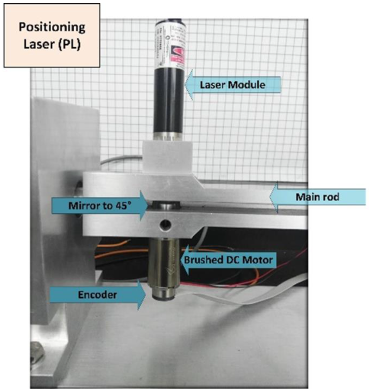
To implement the dynamic triangulation measurement method in practice, the TVS consists mainly of a laser transmitter and receiver. The laser transmitter of our TVS was realized as the Positioning Laser (PL), shown in Fig. 1, and contains the following main components: a Maxon brushed DC motor with incremental encoder providing 1000 pulses per revolution, a 45° cut mirror and a 10 mW laser module. To aim the laser beam precisely at an observed object surface, the actual angular position of the DC motor must be controlled with the smallest possible angular error. This has been achieved by implementing a proportional algorithm (P-Algorithm) in closed-loop (CL) configuration, using a microcontroller (Lindner, Sergiyenko, Rivas-López, Rodríguez-Quiñonez, et al., 2016). In this previous research, the P-algorithm controlled the actual angular position of the DC motor shaft, using a constant reference angular position, which leads to a step response of the DC motor shaft. A positioning time ≤ 100 ms and a relative angular error ≤ 11.10% was achieved (Lindner, Sergiyenko, Rivas-López, Rodríguez-Quiñonez, et al., 2016). Due to static and dynamic non-linear friction effects (Virgala et al., 2013; Virgala & Kelemen, 2013), the DC motor shaft thereby is always positioned with an angular error.

Figure 1 TVS positioning laser. 

Further reduction of the positioning time and relative angular error is desired, thus present paper describes a new approach to control the actual angular position of the PL DC motor, using a trapezoidal profile as trajectory for the reference angular speed ωr(t) of the DC motor. This approach allows a reduction of the positioning time to ≤ 44 ms and a reduction of the relative angular error to ≤ 0.1%, compared to the implementation of a P-algorithm using a microcontroller (Lindner, Sergiyenko, Rivas-López, Rodríguez-Quiñonez, et al., 2016). To design the control system, which applies the trapezoidal trajectory profile for the DC motor velocity in practice, the LM629N-8 IC from Texas Instruments is implemented as a motion controller system specially developed by our research team. The first version of the motion controller systems consists of a self-developed Arduino shield for the Arduino Mega 2560, which can be seen in Fig. 8. The second version of this motion controller is currently being developed by our research team. The paper is organized as follows. After introduction, the next section gives an overview of laser scanners, which or not use cameras, and what essentially distinguishes these systems from our novel approach. The third section describes the used theoretically concepts to reduce the relative angular error of our TVS. The following section four defines the methods used to implement the trapezoidal trajectory profile using the digital controller LM629 and how this controller is integrated in the actual developed TVS. The fifth section describes the experimental realization for determining the actual absolute position error of the TVS PL, which experimental results are summarized in section six. The last section presents conclusions and further research tasks.

Figure 2 Trapezoidal profile for reference angular speed. 

Figure 3 DC motor model with back-EMF. 

Figure 4 DC motor speed control in closed loop. 

Figure 5 LM629 block diagram. 

Figure 6 Front panel of the new developed GUI using the LabVIEW platform. 

Figure 7 LM629 connection diagram. 

Figure 8 TVS PL hardware connections. 

2. Related works

Laser scanners, which use cameras to detect the reflected laser beam, can be found in numerous and even older articles. Schmalfus presents one of the first papers which compares laser scanners versus CCD cameras for automated industrial inspection (Schmalfuß, 1990). Podsedkowski et al. (1999) present a method for robot navigation, using different sensors for estimating current position and orientation of the mobile robot system. The robot orientation system is based on a laser scanner brand SICK LS200. The combination of both laser scanner and camera is used in (Acosta et al., 2006), which introduces the design and development of a 3D scanner, using a line laser and a webcam. From this point, an increasing amount of research about laser triangulation using cameras is widely found in scientific literature (Abu-Nabah et al., 2016; Emam et al., 2014; Idrobo-Pizo et al., 2019; Kienle et al., 2020; Kim et al., 2018; Lee et al., 2017; Lehtomäki et al., 2016; Lin et al., 2017; Mill et al., 2013; Xiao et al., 2015). However, research that implements 3D scanners without cameras is much less available. After an intensive literature search, no work on 2D or 3D scanners was found that only uses off-the-shelf optical and electromechanical elements, to implement the laser scanner. This means, that in all found research a standard industrial 2D or 3D laser from different brands was used. The literature review also revealed, that for moving and positioning these laser scanners also industrial solutions, in the form of servo systems (electrical motor and controller), was used. Kolu et al. (2015) describes an obstacle mapping method for navigating a multipurpose loader, using a tilted 2D laser-servo system, consisting of a SICK laser scanner and a tilting servo module. Martinez et al. describes the construction and calibration of a low cost 3D laser scanner for mobile robot navigation (Martínez et al., 2015), which furthermore uses a DC servomotor equipped with a gear unit. Using a gear units increase the systematical error of the system, which among others is due to the backlash present in every gear. Also, this work uses a Hokuyo laser scanner, which represents a high-cost commercial solution. Moon et al. (2015) offers a 3D laser range finder for object recognition, which also uses a high cost industrial solution from SICK. The presented system consists of a 2D laser range sensor working measurement and a servo drive controlled by an embedded computer running Linux. Bauersfeld et al. (2019) present a 3D laser scanner, developed by adding an additional axis of rotation to a planar tilted 2D laser scanner, which is moved using a Dynamixel servomotor. As last example Singh et al. (2020) presents a modified 3D laser system assembled from a 2D laser scanner coupled with a servomotor is presented. The UTM-30LX laser scanner is coupled with a servomotor, which are used to generate a 3D point cloud for mobile robot navigation. Also, most research developing 2D or 3D scanners does not use open-source hardware or free software. For example, Viola et al. (2017) design and evaluate a fractional order PID controller, whereby different control strategies are implemented using the MATLAB stateflow toolbox and a NI data acquisition system. To prove the proposal of an DC motor speed regulator using active damping, Kim and Ahn (2021) uses a Quanser QUBE-Servo2 and the myRIO-1900.

In summary, it can be said, that after intensive literature research, not a single project was found, which pursues our novel approach of combining a laser triangulation system with DC motors, without using cameras. The unique design principle of our Technical Vision System is described in numerous previous research (Básaca-Preciado et al., 2014; Lindner, Sergiyenko, Rivas-López, Hernández-Balbuena, et al., 2017; Lindner, Sergiyenko, Rivas-López, Ivanov, et al., 2017; Lindner, Sergiyenko, Rivas-López, Rodríguez-Quiñonez, et al., 2016; Lindner, Sergiyenko, Rivas-López, Valdez-Salas, et al., 2016; Lindner, Sergiyenko, Rodríguez-Quiñonez, et al., 2016; Reyes-Garcia et al., 2018, 2018; Reyes-García et al., 2019; Rodríguez-Quiñonez, Sergiyenko, Hernandez-Balbuena, et al., 2014; Rodríguez-Quiñonez, Sergiyenko, Preciado, et al., 2014) and partly presented in this paper. This can be summarized by the following properties. Our system represents a single-sensor, high-speed, ultra low-cost laser scanning system, which uses the dynamic triangulation measurement method and DC motors controlled in CL configuration, to physically measure 3D coordinates of any object under observation, without using large post-processing or cameras. It must be emphasized that for the TVS mechanical design no gears have been implemented, to further reduce the systematic error, caused by gear backlash and other non-linear effects of gear mechanism. All DC motors are controlled directly and without gears in CL configuration, which reduces the absolute angular error and the positioning time of all TVS DC motors shaft. It must also be emphasized, that for the overall TVS design only off-the-shelf mechanical, electromechanical and optical elements and open-source hard and free software tools were considered, which highly reduces the complexity and highly improves the reproducibility of our 3D laser scanning system.

3. Theoretical concepts

Previous research has shown the reduction of the angular error φe of the TVS PL DC motor shaft, by improving the CL positioning algorithm and using high-quality DC motors. In addition, the positioning time (step response rising time trise) has been reduced, maintaining the relative angular error less than 1 per cent (Lindner, Sergiyenko, Rivas-López, Hernández-Balbuena, et al., 2017). However, due to static friction in the ball bearings of the DC motor, an angular error φ e no-zero will always be presented, which can be estimated using a non-linear friction model (Lindner, Sergiyenko, Rivas-López, Ivanov, et al., 2017). Note, that if a constant value is used for the reference angular position φ r = const., then the actual angular position φot of the DC motor shaft is stabilized around the final angular position φ = φo(t  ), resulting in a greater final angular position error φe(t  ) = φr - φ due to the second order system response and the overshoot of the DC motor. On the other hand, if a trapezoidal profile is used for the reference angular speed ωr(t), which by integrating results in the reference angular position φr(t) as a ramp function, the actual angular position of the DC motor shaft φo(t) is stabilized around this ramp function using a PID controller, resulting in a smaller final angular position error and preventing the overshoot of the DC motor shaft. Fig. 2 shows the trapezoidal profile for the reference angular speed ωr(t), with τ3 = τ1 + τ2, which can be expressed using the unit step function σ(t):

ωrt=ωmaxτ1tσt-σt-τ12-σt-τ22-σt-τ32, (1)

transforming (1) to the frequency domain Lωrt=Ωrs, it yields:

Ωrs=ωmaxs2τ11-exp-sτ1-exp-sτ2+exp-sτ3. (2)

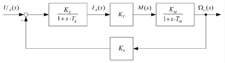
The well-known model of a DC motor with permanent magnets and back-EMF in the frequency domain is depicted in Fig. 3 and can be found in most literature (Chapman, 1985; Fischer, 2016; Hughes & Drury, 2019).

Here, K E represents the electrical gain, K T the torque constant, K M the mechanical gain, K b the back-EMF gain, T E the electrical time constant and T M the mechanical time constant, which are usually provided by the data sheet. The corresponding transfer function of the DC motor is represented by:

GOLs=ΩOsUAs=KEKTKM1+KEKTKb+sTE+TM+s2(TETM), (3)

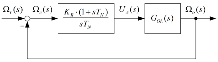
Fig. 4 depicts the DC motor speed control in closed-loop configuration, using a PI-controller. The gain of the PI-controller is K R and the reset time T N . The integral part of the controller is necessary since, when the angular speed error e = 0, a constant angular voltage U A must be generated, hence the DC motor continues to rotate with a constant actual angular velocity o = r.

The corresponding transfer function of the DC motor speed control in closed-loop configuration can be represented as a third-order rational function:

GCLs=ΩOsUrs=b1s+b0a3s3+a2s2+a1s+a0 (4)

Using the final value theorem of the Laplace transform, the final value of the actual angular position φ, when applying a trapezoidal input, shall be calculated:

φ=lims0s·1s ΩO(s)=lims0Ωr(s)·GCL· (5)

Using (2), (4) and evaluating this expression yields an indeterminate form. Applying twice L’Hopital’s rule and using τ3 = τ1 + τ2 yields the final value:

φ=ωmax(τ32-τ22-τ12)2τ1a0=ωmax.τ2. (6)

Thus, a possibility was found to define the final value of the DC motor shaft actual angular position using only two parameters ωmax and τ2. This defines a mathematical relationship between the shape of the trapezoidal velocity profile ωr(t) (Fig. 2) and the DC motor shaft final angular position φ.

4. Methodology

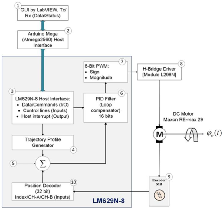
Fig. 5 depicts the block diagram of the LM629 implementation as digital controller in the TVS PL, which consists of 10 principal components. Starting with the first component, a Graphical User Interface (GUI) was developed to monitor the actual DC motor shaft position and velocity, as well as provides global commands for the digital controller LM629. The GUI represents the Software Interface (1). The next component represents the Hardware Interface (2) between the user and the digital controller LM629, implemented using an Arduino Mega, which receives and sends single data strings to the LM629 Host-Interface (3), translating the user commands for the digital controller. The string data is divided per each command, coefficient and values, necessary to load the reference trajectory using the Trajectory Profile Generator (4).

The digital controller also contains a summing junction (5), a position encoder (10) and a digital PID loop compensation filter (6), which calculates a newset point as reference value for the DC motor. The control signal from the PID filter is sent to an 8-bit PWM block (7), which generates a PWM signal, and which than is amplified using the motor driver Hbridge module L298N (8). The control signal from the PID filter is sent to an 8-bit PWM block (7), which generates a PWM signal, and which is then amplified using the motor driver H-bridge module L298N (8).

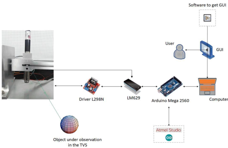
Finally, the output signal of the incremental encoder (9) is detected by the position feedback interface of the LM629 (10). Fig. 7 shows the overall connection diagram of the PL DC motor shaft position control, using the digital controller LM629 in closed-loop configuration.

5. Experimental realization

According to previous section methodology, the LM629 connection diagram (Fig. 7) was developed, which represents the design of the new approach for controlling the TVS PL. The developed hardware connections and hardware algorithms were oriented for intercommunication, reading and writing operations and control logical signals, using as host an Arduino Mega, the LM629 precision motion controller, a L298N dual full bridge driver and the Maxon brushed DCX motor, which represents the actuator for the TVS PL. The developed 
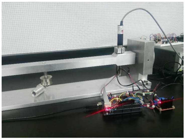
experimental hardware connections are depicted in Fig. 
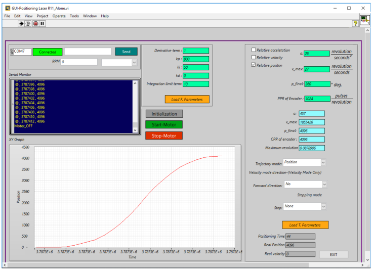
8. After the experimental hardware implementation, a GUI was developed based on the LabVIEW platform, to interact with the LM629 precision motion controller. Fig. 6 depicts the front panel of the GUI, which shows the tracking of the positioning laser, using the data formatted as (x: time, y: position) and displayed in a XY Graph, to determine the DC motor shaft actual angular position φo(t).

All used experimental parameters are summarized in Table 1, which represents the minimum data required for positioning the DC motor shaft.

Table 1 Defined experimental parameters. 

Symbol Description Value Unit
φ r Reference angular position Variable double type arc degrees (°)
φ o Actual angular position Variable double type arc degrees (°)
φ e Absolute angular error Variable double type arc degrees (°)
φ’ e Relative angular error Variable double type percentage (%)
φ-'e Relative angular error average Variable double type percentage (%)
N r Counts per reference angular position Variable double type counts
N m Counts per actual angular position Variable double type counts
a Reference acceleration 26 rev/s2
ω max Reference maximum velocity 27 rev/s

The desired angular displacements of the laser beam are represented in values of the reference angular position φr(t).

The DC motor shaft actual angular position is represented by φo(t). The relative angular error φe' and relative angular error average φ-e' are defined by:

φe'=Nr-NmNr·100, (7)

φ-e'=15i=15φei.    (8)

The actuator of the TVS PL includes an incremental encoder of 1024 pulses per revolution as angular resolution. Using the LM629 motor position decoder module, the digital controller quadruples this angular resolution defined by the LM629 data sheet, resulting in a maximum possible angular resolution of ϱmax  0.08789°. Since the encoder outputs a digital signal and its function does not depend on calibration, the resolution of the encoder can be directly related to the measurement uncertainty of this digital signal. The counts per reference angular position Nr are defined by:

Nrφrϱmax, (9)

and the counts per actual angular position Nm(t) represent the discretized actual angular position φo(t). Here, counts means the counted pulses of the DC motor encoder. Note, that the digital controller rounds the actual angular position φo up to the next higher discretized value in Nm counts. The acceleration a(t) and maximum velocity ωmax(t) represent trajectory parameters. When executing the GUI for the first time, the experimental hardware processes the software flow defined by the LM629 programming guide. Thereby, two highlighted stages are executed. The first stage evaluates the optimal response of the DC motor shaft, searching for optimal values of PID control algorithm coefficients: k p , k i , and k d , which were tested using an empirical method and are summarized in Table 2. The coefficients of the PID control algorithm were also confirmed using simulation.

Table 2 Experimental coefficients for feedback control. 

Controller k p k i k d
P 40 - -
PI 1000 50 -

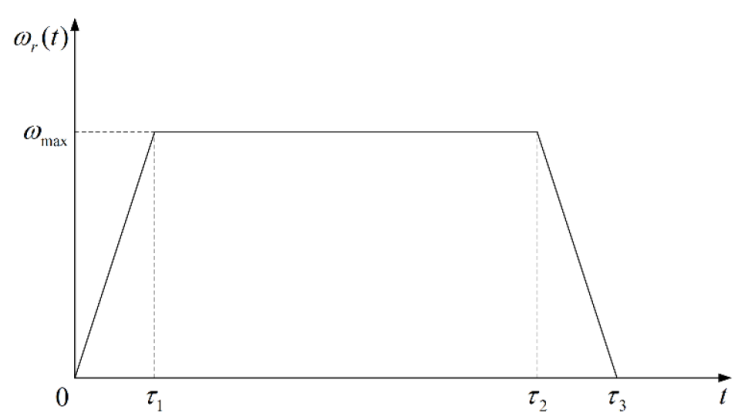
The second stage consists in setting up the trapezoidal velocity trajectory ωr(t), entering the values: φr, a, and ωmax, which are downloaded to the LM629 from the GUI. After evaluating the hardware and software configuration, 25 tests were made using as reference angular position φr = 1°, 5°, 15°, 90° and 360°.

6. Experimental results

During the experiment, various observations were made. The DC motor shaft was positioned using as acceleration a = 26 rev/s2 and as maximum velocity ωmax=27 rev/s, taking a sample interval of T s = 256 µs. Table III summarizes all 25 tests submitted in experimental realization, evaluating the behavior of the DC motor shaft actual angular position and using as reference angular positions φr = 1°, 5°, 15°, 90° and 360°. Each reference angular position φ r was used with 5 tests, to calculate the relative angular error φe'. The results in Table III show clearly, that by using the digital controller LM629, the DC motor shaft actual angular position is controlled with an absolute position error smaller than ϱmax. That is the reason, why in Table 3 the relative angular error φe' is almost always zero. That means, since the positioning error is smaller than the resolution of the measuring system ϱmax, the absolute position error φ e cannot be measured with the LM629. In addition to the advantage of higher positioning accuracy, also the step response of the TVS PL DC motor shaft was accelerated, resulting in positioning times shorter than 44 ms.

Table 3 Experimental results. 

φ r N r N m φe'(%) t p (ms)
1°ϱmax11 11 0 1
11 0 1
11 0 1
11 0 1
11 0 1
5°ϱmax57 57 0 1
57 0 1
57 0 1
57 0 1
57 0 1
15° 15°ϱmax171 171 0 2
171 0 3
171 0 4
171 0 2
171 0 2
90° 90°ϱmax1024 1024 0 22
1024 0 21
1024 0 25
1024 0 22
1024 0 22
360° 360°ϱmax4096 4095 0.02 44
4096 0 42
4096 0 43
4096 0 44
4096 0 44

7. Conclusions

Present paper explores a new methodology to further reduce the angular error of a laser scanning machine vision system using a trapezoidal trajectory profile for the TVS PL mechanical actuators (DC motors). Thereby, the step response of the DC motors is replaced by a trajectory response, using a trapezoidal profile for the DC Motor velocity, to reduce the angular error of the DC motor shaft. The trapezoidal profile for the DC Motor velocity is implemented using the digital controller LM629. This approach reduces significantly the relative angular error to a value less than or equal 0.1%, compared to the previously used step response (Lindner, Sergiyenko, Rivas-López, Rodríguez-Quiñonez, et al., 2016). The results in Table III show the advantages of using a trapezoidal velocity trajectory ωr(t) over a constant value for the reference angular position φr(t), resulting in higher precision and higher accuracy in each of the realized 25 tests. Table IV shows the main results of the comparison of the step response (Lindner, Sergiyenko, Rivas-López, Rodríguez-Quiñonez, et al., 2016) with the actual developed trajectory response, using a trapezoidal profile for the DC Motor velocity. As shown in this table, the relative angular error was reduced from a maximum of 11.1% to a maximum of 0.1% and the positioning time from a maximum of 100 ms to a maximum of 44 ms. That means an improvement of the relative angular error by  99.1% and the positioning time by  54%. However, it is important to determine the reliability of this new approach, considering experimental results of Table 3, when comparing them with other experimental results. Further research tasks are defined by the verification of experimental results (Table 3) using physical measurements, as well as the comparison of the digital controller LM629 against industrial positioning controllers, like for example the Maxon EPOS 24/1. Also, for the moment we are still working on optimizing the receiving part of the TVS in order to detect the reflected laser beam faster, with higher accuracy and higher precision. Hence, extensive experiments using different objects, surfaces, colors, etc. will also be subject of future tasks.

Table 4 Step vs. trajectory response. 

Factor Step response Trajectory response
Relative angular error ≤ 11.10 % ≤ 0.1 %
Positioning time ≤ 100 ms ≤ 44 ms

References

Abu-Nabah, B. A., ElSoussi, A. O., & Al Alami, A. E. K. (2016). Simple laser vision sensor calibration for surface profiling applications.Optics and Lasers in Engineering,84, 51-61. https://doi.org/10.1016/j.optlaseng.2016.03.024 [ Links ]

Acosta, D., Garcia, O., & Aponte, J. (2006). Laser Triangulation for Shape Acquisition in a 3D Scanner Plus Scan. Electronics, Robotics and Automotive Mechanics Conference (CERMA’06), 2, 14-19. https://doi.org/10.1109/CERMA.2006.54 [ Links ]

Básaca-Preciado, L. C., Sergiyenko, O. Yu., Rodríguez-Quinonez, J. C., García, X., Tyrsa, V. V., Rivas-Lopez, M., Hernandez-Balbuena, D., Mercorelli, P., Podrygalo, M., Gurko, A., Tabakova, I., & Starostenko, O. (2014). Optical 3D laser measurement system for navigation of autonomous mobile robot. Optics and Lasers in Engineering, 54, 159-169. https://doi.org/10.1016/j.optlaseng.2013.08.005 [ Links ]

Bauersfeld, L., & Ducard, G. (2019). Low-cost 3D Laser Design and Evaluation with Mapping Techniques Review. 2019 IEEE Sensors Applications Symposium (SAS), 1-6. https://doi.org/10.1109/SAS.2019.8706006 [ Links ]

Chapman, S. J. (1985). Electric Machinery Fundamentals. McGraw-Hill. [ Links ]

Emam, S. M., Khatibi, S., & Khalili, K. (2014). Improving the Accuracy of Laser Scanning for 3D Model Reconstruction Using Dithering Technique. Procedia Technology, 12, 353-358. https://doi.org/10.1016/j.protcy.2013.12.498 [ Links ]

Fischer, R. (2016). Elektrische Maschinen. En R. Fischer (Ed.), Elektrotechnik für Maschinenbauer: Sowie für Studierende der Versorgungstechnik, des Wirtschaftsingenieurwesens und anderer technischer Fachbereiche (pp. 269-377). Springer Fachmedien. https://doi.org/10.1007/978-3-658-12515-8_4 [ Links ]

Hughes, A., & Drury, B. (2019). Electric Motors and Drives: Fundamentals, Types and Applications. Newnes. [ Links ]

Idrobo-Pizo, G. A., Motta, J. M. S. T., & Sampaio, R. C. (2019). A Calibration Method for a Laser Triangulation Scanner Mounted on a Robot Arm for Surface Mapping. Sensors, 19(8), Art. 8. https://doi.org/10.3390/s19081783 [ Links ]

Kienle, P., Batarilo, L., Akgül, M., Köhler, M. H., Wang, K., Jakobi, M., & Koch, A. W. (2020). Optical Setup for Error Compensation in a Laser Triangulation System. Sensors, 20(17), Art. 17. https://doi.org/10.3390/s20174949 [ Links ]

Kim, S. H., Lee, S. J., & Kim, S. W. (2018). Weaving Laser Vision System for Navigation of Mobile Robots in Pipeline Structures. IEEE Sensors Journal, 18(6), 2585-2591. https://doi.org/10.1109/JSEN.2018.2795043 [ Links ]

Kim, S.-K., & Ahn, C. K. (2021). DC Motor Speed Regulator via Active Damping Injection and Angular Acceleration Estimation Techniques. IEEE/CAA Journal of Automatica Sinica, 8(3), 641-647. https://doi.org/10.1109/JAS.2020.1003548 [ Links ]

Kolu, A., Lauri, M., Hyvönen, M., Ghabcheloo, R., & Huhtala, K. (2015). A mapping method tolerant to calibration and localization errors based on tilting 2D laser scanner. 2015 European Control Conference (ECC), 2348-2353. https://doi.org/10.1109/ECC.2015.7330889 [ Links ]

Lee, M.-J., Baek, S.-H., & Park, S.-Y. (2017). 3D foot scanner based on 360 degree rotating-type laser triangulation sensor. 2017 56th Annual Conference of the Society of Instrument and Control Engineers of Japan (SICE), 1065-1070. https://doi.org/10.23919/SICE.2017.8105700 [ Links ]

Lehtomäki, M., Jaakkola, A., Hyyppä, J., Lampinen, J., Kaartinen, H., Kukko, A., Puttonen, E., & Hyyppä, H. (2016). Object Classification and Recognition From Mobile Laser Scanning Point Clouds in a Road Environment. IEEE Transactions on Geoscience and Remote Sensing, 54(2), 1226-1239. https://doi.org/10.1109/TGRS.2015.2476502 [ Links ]

Lin, W., Meng, Y., Qiu, Z., Zhang, S., & Wu, J. (2017). Measurement and calculation of crown projection area and crown volume of individual trees based on 3D laser-scanned point-cloud data. International Journal of Remote Sensing, 38(4), 1083-1100. https://doi.org/10.1080/01431161.2016.1265690 [ Links ]

Lindner, L., Sergiyenko, O., Rivas-López, M., Hernández-Balbuena, D., Flores-Fuentes, W., Rodríguez-Quiñonez, J. C., Murrieta-Rico, F. N., Ivanov, M., Tyrsa, V., & Básaca-Preciado, L. C. (2017). Exact laser beam positioning for measurement of vegetation vitality. Industrial Robot: An International Journal, 44(4), 532-541. https://doi.org/10.1108/IR-11-2016-0297 [ Links ]

Lindner, L., Sergiyenko, O., Rivas-López, M., Ivanov, M., Rodríguez-Quiñonez, J. C., Hernández-Balbuena, D., Flores-Fuentes, W., Tyrsa, V., Muerrieta-Rico, F. N., & Mercorelli, P. (2017). Machine vision system errors for unmanned aerial vehicle navigation. 2017 IEEE 26th International Symposium on Industrial Electronics (ISIE), 1615-1620. https://doi.org/10.1109/ISIE.2017.8001488 [ Links ]

Lindner, L., Sergiyenko, O., Rivas-López, M., Rodríguez-Quiñonez, J. C., Hernández-Balbuena, D., Flores-Fuentes, W., Tyrsa, V., Nieto Hipolito, J. I., Muerrieta-Rico, F. N., & Kartashov, V. M. (2016). Issues of exact laser ray positioning using DC motors for vision-based target detection. 2016 IEEE 25th International Symposium on Industrial Electronics (ISIE), 929-934. https://doi.org/10.1109/ISIE.2016.7745015 [ Links ]

Lindner, L., Sergiyenko, O., Rivas-López, M., Valdez-Salas, B., Rodríguez-Quiñonez, J. C., Hernández-Balbuena, D., Flores-Fuentes, W., Tyrsa, V., Barrera, M. M., Muerrieta-Rico, F. N., Mercorelli, P., & Gurko, A. (2016). UAV remote laser scanner improvement by continuous scanning using DC motors. IECON 2016 - 42nd Annual Conference of the IEEE Industrial Electronics Society, 371-376. https://doi.org/10.1109/IECON.2016.7793316 [ Links ]

Lindner, L., Sergiyenko, O., Rodríguez-Quiñonez, J. C., Rivas-Lopez, M., Hernandez-Balbuena, D., Flores-Fuentes, W., Natanael Murrieta-Rico, F., & Tyrsa, V. (2016). Mobile robot vision system using continuous laser scanning for industrial application. Industrial Robot: An International Journal, 43(4), 360-369. https://doi.org/10.1108/IR-01-2016-0048 [ Links ]

Martínez, J. L., Morales, J., Reina, A. J., Mandow, A., Pequeño-Boter, A., & García-Cerezo, A. (2015). Construction and calibration of a low-cost 3D laser scanner with 360° field of view for mobile robots. 2015 IEEE International Conference on Industrial Technology (ICIT), 149-154. https://doi.org/10.1109/ICIT.2015.7125091 [ Links ]

Mill, T., Alt, A., & Liias, R. (2013). Combined 3D building surveying techniques - terrestrial laser scanning (TLS) and total station surveying for BIM data management purposes. Journal of Civil Engineering and Management, 19(sup1), S23-S32. https://doi.org/10.3846/13923730.2013.795187 [ Links ]

Moon, Y.-G., Go, S.-J., Yu, K.-H., & Lee, M.-C. (2015). Development of 3D laser range finder system for object recognition. 2015 IEEE International Conference on Advanced Intelligent Mechatronics (AIM), 1402-1405. https://doi.org/10.1109/AIM.2015.7222736 [ Links ]

Podsedkowski, L., Nowakowski, J., Idzikowski, M., & Visvary, I. (1999). Online navigation of mobile robots using laser scanner. Proceedings of the First Workshop on Robot Motion and Control. RoMoCo’99 (Cat. No.99EX353), 241-245. https://doi.org/10.1109/ROMOCO.1999.791082 [ Links ]

Reyes-Garcia, M., Lindner, L., Rivas-López, M., Ivanov, M., Rodriguez-Quiñonez, J. C., Flores-Fuentes, W., Murrieta-Rico, F. N., Gurko, A., & Melnyk, V. (2018). Reduction of Angular Position Error of a Machine Vision System Using the Digital Controller LM629. IECON 2018 - 44th Annual Conference of the IEEE Industrial Electronics Society, 3200-3205. https://doi.org/10.1109/IECON.2018.8592803 [ Links ]

Reyes-García, M., Sergiyenko, O., Ivanov, M., Lindner, L., Rodríguez-Quiñonez, J. C., Hernandez-Balbuena, D., Flores-Fuentes, W., Tyrsa, V., Moreno-Ahedo, L. O., & Murrieta-Rico, F. N. (2019). Defining the Final Angular Position of DC Motor shaft using a Trapezoidal Trajectory Profile. 2019 IEEE 28th International Symposium on Industrial Electronics (ISIE), 1694-1699. https://doi.org/10.1109/ISIE.2019.8781093 [ Links ]

Rodríguez-Quiñonez, J. C., Sergiyenko, O., Hernandez-Balbuena, D., Rivas-Lopez, M., Flores-Fuentes, W., & Basaca-Preciado, L. C. (2014). Improve 3D laser scanner measurements accuracy using a FFBP neural network with Widrow-Hoff weight/bias learning function. Opto-Electronics Review, 22(4), 224-235. https://doi.org/10.2478/s11772-014-0203-1 [ Links ]

Rodríguez-Quiñonez, J. C., Sergiyenko, O. Yu., Preciado, L. C. B., Tyrsa, V. V., Gurko, A. G., Podrygalo, M. A., Lopez, M. R., & Balbuena, D. H. (2014). Optical monitoring of scoliosis by 3D medical laser scanner. Optics and Lasers in Engineering, 54, 175-186. https://doi.org/10.1016/j.optlaseng.2013.07.026 [ Links ]

Schmalfuß, H. J. (1990). Laser scanner versus CCD camera: A comparison. Industrial Metrology, 1(2), 155-164. https://doi.org/10.1016/0921-5956(90)80024-P [ Links ]

Sergiyenko, O., & Rodriguez-Quiñonez, J. C. (2016). Developing and Applying Optoelectronics in Machine Vision. IGI Global. [ Links ]

Singh, R., Khurana, A., & Kumar, S. (2020). Optimized 3D laser point cloud reconstruction by gradient descent technique. Industrial Robot: the international journal of robotics research and application, 47(3), 409-421. https://doi.org/10.1108/IR-12-2019-0244 [ Links ]

Viola, J., Angel, L., & Sebastian, J. M. (2017). Design and robust performance evaluation of a fractional order PID controller applied to a DC motor. IEEE/CAA Journal of Automatica Sinica, 4(2), 304-314. https://doi.org/10.1109/JAS.2017.7510535 [ Links ]

Virgala, I., Frankovský, P., & Kenderová, M. (2013). Friction Effect Analysis of a DC Motor. American Journal of Mechanical Engineering, 1(1), Art. 1. https://doi.org/10.12691/ajme-1-1-1 [ Links ]

Virgala, I., & Kelemen, M. (2013). Experimental Friction Identification of a DC Motor. International Journal of Mechanics and Applications, 3(1), 26-30. [ Links ]

Xiao, J., Hu, X., Lu, W., Ma, J., & Guo, X. (2015). A new three-dimensional laser scanner design and its performance analysis. Optik, 126(7), 701-707. https://doi.org/10.1016/j.ijleo.2015.02.007 [ Links ]

Zhang, J., & Singh, S. (2017). Low-drift and real-time lidar odometry and mapping. Autonomous Robots, 41(2), 401-416. https://doi.org/10.1007/s10514-016-9548-2 [ Links ]

Peer Review under the responsibility of Universidad Nacional Autónoma de México.

Financing. The authors received no specific funding for this work.

Received: October 01, 2021; Accepted: December 10, 2021; Published: December 31, 2022

Corresponding author. E-mail address: fnmurrietar@upbc.edu.mx (Fabian N. Murrieta-Rico).

Conflict of interest. The authors have no conflict of interest to declare.

Creative Commons License This is an open-access article distributed under the terms of the Creative Commons Attribution License