


 nueva página del texto (beta)
 Inglés (pdf)
 Artículo en XML
 Referencias del artículo
 Enviar artículo por email
 Citado por SciELO
  Similares en
SciELO
Similares en
SciELO 
 Permalink
1. Introduction
The prime driver for development of tungsten heavy alloy is its application in kinetic energy penetrator ammunitions. With emergence of improved armour materials providing enhanced protection to battle tanks, there is a need for development of kinetic energy penetrators with improved ballistic performance. Currently, the desired depth of penetration (DOP) of kinetic energy penetrators is in excess of 600mm, which necessitates development of heavy alloys with enhanced properties as they form the core rod of the ammunition and are subjected to sudden surge in stress during the launch. Modification of alloy composition that includes W, Ni and Fe with alloying addition such as Co (Cury et al., 2013; Katavic et al., 2008; Penrice & Bost, 1988; Stuitje et al., 1995), Ta (Xing-long et al., 2004), Mn (Bose et al., 1991; Bose et al., 1992), Mo (Kemp & German, 1995) and Re (Liu et al., 2008) has been attempted with beneficial effects. These additives (sometimes termed as dopants) mostly partition to the matrix phase thereby influencing the microstructure and mechanical properties of the two phase aggregate comprising round tungsten particles (15-40 µm) and a matrix solid solution that is a continuous phase.
The presence of Coin W-Ni-Fe alloys has resulted in enhanced mechanical properties primarily because of two reasons: 1) increased solubility of W in the matrix phase leading to solid solution strengthening and 2) increased wettability of the liquid phase (matrix) during sintering resulting in reduced W-W contiguity (Spencer et al., 1992). Later generation of heavy alloys has completely substituted Fe with Co resulting in ternary W-Ni-Co alloys (Stuitje et al., 1995). These alloys require a specialised cyclic heat treatment so as to generate a two phase matrix microstructure containing micron-sized W precipitates (~1µm) in the matrix. In contrast, the matrix of Fe containing tungsten alloys e.g., W-Ni-Fe or W-Ni-Fe-Co is single phase. Thus, the microstructural modification of tungsten heavy alloy in W-Ni-Co alloy possibly points towards a major shift in the way microstructures are tailored in these alloys. The advantage of two phase matrix is substantially enhanced strength. While the alloys have found use in state of the art KE penetrators, the studies on the mechanical behaviour of these alloys are relatively scarce (Kocich et al., 2016; Bless et al., 2006). The study is also of fundamental interest given that the microstructure specifically the matrix phase is substantially different from that observed in the earlier generation alloys (W-Ni-Fe, W-Ni-Fe-Co, W-Ni-Fe-Co-Mo etc.).
The present study investigates the mechanical behaviour of a W-Ni-Co alloy with 90% W (nominal composition listed in Table 1). The alloy has been produced by liquid phase sintering followed by cyclic heat treatment: (850⁰C for 3h) + (1150⁰C for 1.5 h), to obtain micron-sized W precipitates in the matrix phase. Tensile and impact properties have been evaluated. Another alloy based on W-Ni-Fe-Co system with similar density has been processed following a standard heat treatment (1150°C/ water quench) and evaluated to generate the base line data. This is followed by a comparison of the mechanical behaviour of these two alloys and structure- property correlation.
2. Experimental
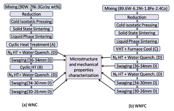
90W-7Ni-3Co (herein-after referred to as WNC alloy) and 89.6W-6.2Ni-1.8Fe-2.4Co (herein-after referred to as WNFC alloy) alloys were processed according to the process flow chart shown in Fig. 1. Tungsten, nickel, iron and cobalt powders, as per the composition of WNC and WNFC alloys, were mixed for duration of 24 h in a conventional ball mill using stainless steel balls and ball to powder ratio (BPR) of 1:1. The powder mix of both the compositions were then reduced at 700˚C for 2 h in a hydrogen atmosphere reduction furnace (Sintering and Brazing Furnace Ltd., India) to remove oxides and oxygen enriched layers that form during mixing. Reduced powder blends of both the compositions were then cold isostatically pressed (National Forge, Belgium) at 200 MPa to obtain cylindrical green compacts of dimensions 55mm dia. and 300 mm length.
The green compacts were then pre-sintered at 1300˚C for 1 h followed by liquid phase sintering between 1480˚C and 1490˚C for 75 min in a pusher type hydrogen atmosphere sintering furnace (FHD Furnaces Ltd, England). Heating rate was maintained at 5˚C/min during pre-sintering and liquid phase sintering. Dew point of hydrogen during sintering was maintained at -35˚C.
After sintering, WNC alloy was subjected to cyclic heat treatment in a vacuum furnace. The details of different heat treatments used for processing the alloys are produced in Table 2. One cycle of cyclic heat treatment, as shown in Fig. 2, includes an initial low temperature hold at 850°C for 3h followed by a high temperature treatment at 1150˚C for 1.5 h. In the present study, WNC alloy is subjected to a cyclic heat treatment that consists of four such uninterrupted cycles with subsequent furnace cooling. This heat treatment is designated as cyclic heat treatment (A). WNFC alloy when subjected to cyclic treatment (A) did not exhibit the presence of fine precipitates (Ws) in the matrix phase. Therefore, unlike WNC alloy, WNFC alloy was not subjected to cyclic heat treatment (A). Instead, as shown in Fig. 1, it was heat treated in vacuum for removal of hydrogen (1150°C/4h/Furnace cool). Subsequently, both WNC alloy (in cyclic heat treated (A) condition) and WNFC alloy (in vacuum heat treated condition) were again heat treated in nitrogen furnace at 1150˚C for 4 h followed by water quenching (D).
Table 2 Details of different heat treatments (HT) provided to alloys.
| HT ID | HT parameters | HT atmosp-here | No. Of cycle | Quenching | Remarks |
|---|---|---|---|---|---|
| A | 850°C /3 h + 1150°C/1.5 h | Vacuum | 4 | Furnace cooling | Ws precipitation in matrix |
| B | 850°C/3 h + 1150°C/1.5 h | Vacuum | 2 | Furnace cooling | Ws precipitation in matrix |
| C | 1150°C / 4 h | Vacuum | 1 | Furnace cooling | Hydrogen removal (Degassing) |
| D | 1150°C / 4 h | Nitrogen | 1 | Water Quenching | Suppression of intermetallics |
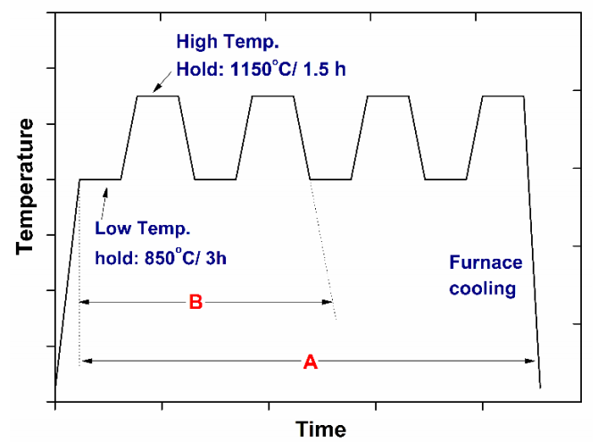
Figure 2 Sketch showing cyclic heat treatment steps for 4 cycles (A) and 2 cycles (B) for WNC alloy.
Quenched blanks of WNC and WNFC alloys were then swaged from an initial diameter of 36 mm to a final diameter of 34 mm. This swaging operation is referred to as first stage swaging. After first stage swaging, WNC alloy was subjected to cyclic heat treatment (B). Cyclic heat treatment B (Fig. 2) includes only two cycles followed by furnace cooling as against four in the first cyclic heat treatment A. Again, WNFC alloy was not subjected to any cyclic heat treatment as shown in Fig. 1.
WNC alloy (in first swage plus cyclic heat treated (B) condition) and WNFC alloy (in first swaged condition) were then heat treated in nitrogen at 1150˚C for 4h followed by water quenching (D). The water quenched blanks of WNC and WNFC alloys were then swaged again from a diameter of 34 mm to 30 mm and then to a final diameter of 26 mm. This swaging operation is referred to as second stage swaging. Cumulative deformation thus imparted on both the alloys, after first and second swaging is 53 %.
Microstructures at different stages of processing were examined using optical and scanning electron microscope (FEI Quanta 400 ESEM). Microstructural parameters such as average grain size and volume fraction of the matrix phase determined using ImageJ software are listed in Table 3. Contiguity (Cg) was determined by line intercept method. The number of tungsten-tungsten contacts (NWW) and tungsten-matrix contacts (NWM) were counted for an average of 180 measurements. Then, contiguity was calculated using the formula:
Table 3 Microstructural parameters of alloys in heat treated and swaged conditions (refer to Table 6a for specimen designation).
| Property | WNC | WNFC | ||
|---|---|---|---|---|
| Treatment | After 1st HT (WNCH) | Final Swaged (WNC26) | After 1st HT (WNFCH) | Final swaged (WNFC26) |
| Contiguity | 0.22 | 0.26 | 0.24 | 0.27 |
| W particle size (µm) | 20.9 ± 8.0 | 14.8 ± 7.2 | 24.1 ± 9.3 | 16.0 ± 6.5 |
| Volume fraction of matrix phase (%) | 25.3 ± 1.6 | 27.9 ± 1.7 | 27.9 ± 0.7 | 21.3 ± 0. 7 |
Table 4 Chemistry of W particles and matrix phase by wave length dispersive analysis.
| S. No. | Alloy | Treatment | Phase | Co (wt %) | Ni (wt %) | Fe (wt %) | W (wt %) |
|---|---|---|---|---|---|---|---|
| 1 | WNC | 850 ⁰C HT | Matrix | 18.7 | 43.3 | 0 | 38.0 |
| Intermetallic | 16.2 | 37.1 | 0 | 46.7 | |||
| W particle | 0.3 | 0 | 0 | 99.7 | |||
| Final swaged (26mm) | Matrix | 18.1 | 42.0 | 0 | 39.9 | ||
| W particle | 0.1 | 0 | 0 | 99.9 | |||
| 2 | WNFC | Final swaged (26mm) | Matrix | 16.6 | 42. 7 | 11.6 | 29.1 |
| W particle | 0.1 | 0 | 0.1 | 99.8 |
Electron probe micro analysis (EPMA-SX-100, Cameca, France) was performed on both the alloys after second stage swaging, to determine the composition of the matrix phase and the tungsten grains. In addition, WNC alloy was also studied using EPMA after the low temperature (850˚C/3h) heat treatment step (as shown in Fig. 2) of the cyclic heat treatment.
Tensile testing of both the alloys was carried out in heat treated and swaged conditions using a screw driven tensile testing machine (Instron 5500R Universal tensile testing machine). Crosshead speed of 1 mm/min which corresponds to a strain rate of 6 x 10⁻⁴/sec was used in the present study. Ultimate tensile strength (UTS), 0.2% yield strength (YS) and % plastic deformation to failure were measured and work hardening exponents were determined from the stress-strain curves. Charpy impact testing was carried out on unnotched samples of dimensions 10 x 10 x 55 mm in a pendulum type impact testing machine (Fuel Instruments-India, Model: IT 30 ASTM). Fractographs of failed tensile and impact samples of both the alloys were examined using scanning electron microscope.
Compression test (rectangular sample: 10 x 5 x 5 mm3) was performed on WNC alloy afterheat treatment (A+D) to observe the interaction of slip bands with precipitates. One surface of the compression test sample was mirror polished prior to the test in order to examine the slip bands or traces. Scanning electron microscope was used to study the presence of slip bands in the compression tested samples. Transmission electron microscopy was also performed on the compression tested samples of WNC alloy to study the dislocation substructure in the matrix phase.
3. Results
3.1. Microstructure
Back scattered electron micrographs of WNC and WNFC alloys in as-sintered condition are shown in Fig. 3. The microstructure comprises nearly-round tungsten particles surrounded by a continuous matrix phase. The matrix phase in both the cases remains clean, devoid of any precipitates. Microstructure of WNC and WNFC alloy obtained after (i) low temperature treatment (850˚C for 3 h followed by furnace cool) of cyclic heat treatment are shown in Fig. 4a and 4b.
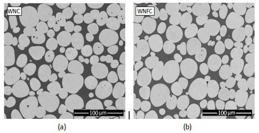
Figure 3 Back scattered electron images of as sintered (a)WNC and (b) WNFC showing nearly round tungsten grains surrounded by a continuous matrix phase.
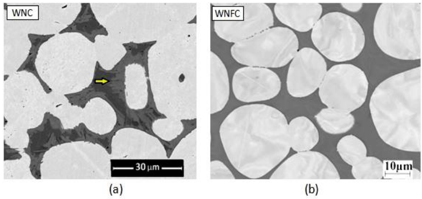
Figure 4 Microstructures of: (a) WNC and (b) WNFC after intermediate heat treatment (850 °C/3 h). WNC forms a new phase with intermediate grey contrastlevel, as shown by arrow in Fig. (a).
As observed in the above Figure, the matrix phase of WNC alloy has an additional phase with a contrast level that is intermediate between that of the bright tungsten grains and the dark matrix phase. This phase, which is reported to be an intermetallic based on Co2W (Stuitje et al., 1995), Microstructure of WNFC subjected to the same low temperature treatment (850⁰C/ 3h/Furnace Cool) of the cyclic treatment (A) does not show any intermetallic phase in the matrix phase and appears clean with uniform contrast a shown in Fig. 4b. Since the intermetallic was not observed, it was decided that WNFC would not be subjected to cyclic treatment. Instead, as shown in Fig. 1, it was given a standard heat treatment that includes 1150°C/4h/Furnace cool (C) in vacuum to remove dissolved hydrogen followed by 1150°C/4h/Water quench under nitrogen furnace (D), which is a standard heat treatment employed in heavy alloys for removal of segregation and homogenisation of microstructure.
Fig. 5a and 5b shows the microstructure of WNC and WNFC respectively, processed through complete cyclic heat treatment A (4 cycles) in vacuum and heat treatment at 1150˚C for 4h in nitrogen atmosphere followed by water quenching (D). As shown in Fig. 5a and also in the high magnification image in Fig. 5c, in addition to round tungsten grains, the WNC microstructure consists of fine tungsten precipitates in the matrix phase. The precipitates exhibit two different morphologies: (i) round and relatively coarser (~1 µm) and (ii) fine needles with high aspect ratio. In addition, the primary tungsten grains show a jagged interface, which is not seen in the as-sintered microstructure.
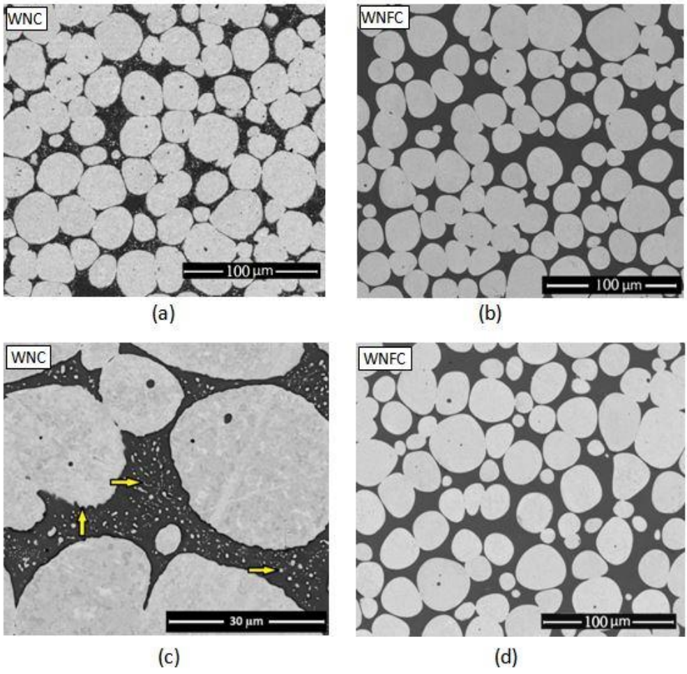
Figure 5 Microstructures of: (a) WNC and (b) WNFC after cyclic heat treatment (850 °C/3 h + 1150 °C/1.5 h) (A) followed by 1150°C/WQ (D) WNC forms needle like and round tungsten particles in matrix phase as shown by arrows. Jagged interface of W particles are also shown by arrow. (d) WNFC after 1150°C/WQ (D).
On the other hand, WNFC alloy after same heattreatment shows a matrix that is devoid of fine tungsten precipitates and tungsten grains without jagged interfaces (Fig. 5b).
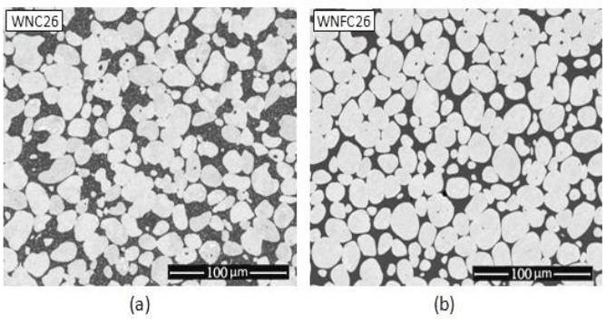
Fig. 6 shows back scattered electron images of both the alloys after final stage swaging designated as WNC26 and WNFC26. It is observed that the tungsten grains in WNC26 alloy adopt marginally angular morphology. Microstructural parameters obtained after HT and final stage swaging are listed in Table 3 which shows: (i) tungsten particle size is marginally finer in WNC alloy in both heat treated and heat treated plus swaged conditions and also decreases with increasing deformation during swaging (ii) contiguity is similar in both the alloys and a slight increase in contiguity is seen in as swaged condition. (iii) the matrix volume fraction remains similar in both the alloys in heat treated and heat treated plus final swaged condition.
3.2. Mechanical behaviour
Microhardness values of the alloys in heat treated and heat treated plus swaged condition (26 mm) are listed in Table 5. While the difference in hardness values of the W particles in both WNC and WNFC alloys is not significant, the matrix phase of WNC alloy is significantly harder in both heat treated and heat treated plus final swaged condition.
Table 5 Microhardness value of alloys after heat teatment and final swaging.
| Hardness values (Hmv) | WNFC | WNC | ||
|---|---|---|---|---|
| W | Matrix | W | Matrix | |
| After 1st Heat Treatment | 442±14.1 | 336.4 ± 12.2 | 410.6 ± 5.0 | 387.9 ± 11.2 |
| As Swaged (26mm) | 594.6 ± 29.2 | 547.0 ± 18.9 | 605.6 ± 33.1 | 587.0 ± 14.0 |
True stress-true plastic strain curves of WNC and WNFC alloys processed with 4 different thermo-mechanical processing conditions are shown in Fig. 7. Corresponding tensile properties are listed in Table 6a and 6b. For a given thermo-mechanical processing condition, yield strength and ultimate tensile strength of WNC alloys are substantially higher than those of WNFC alloy. % elongation of WNFC and WNC alloys are comparable in heat treatment (WNFCH and WNCH) and heat treatment plus first swaged (upto 34 mm that is WNC34 and WNFC34) condition, whereas in the higher WNC30, 26 and WNFC30, 26), the elongationvalues are marginally higher in WNFC alloy as compared to WNC alloy.
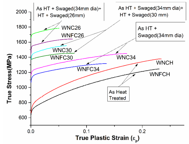
Figure 7 True stress plastic strain curves of WNC and WNFC after different thermos mechanical treatments.
Table 6a Tensile properties of WNC alloys.
| Sample ID | Processing | 0.2% Y.S. (MPa) | UTS (MPa) | Elongation % |
|---|---|---|---|---|
| WNCH | Sintered+ Cyclic Heat treated (A) + Quenched (D) | 708± 14 | 1054 ± 9.9 | 27.6 ± 0 |
| WNC34 | Sintered+ A+D + Swaged (34mm) | 1158 ± 10.7 | 1215 ± 6.0 | 18.7 ± 1.2 |
| WNC30 | Sintered+ A+D + Swaged (34mm) + Cyclic Heat treated (B) +D + Swaged (30mm) | 1379 ±1.5 | 1445 ±16.6 | 7.4 ± 1 |
| WNC26 | Sintered+ A+D + Swaged (34mm) + B+D + Swaged (26mm) | 1635 ± 28 | 1660 ± 26 | 5 ± 1 |
Table 6b Tensile properties of WNFC alloys.
| Sample ID | Processing | 0.2% Y.S. (MPa) | UTS (MPa) | Elongation % |
|---|---|---|---|---|
| WNFCH | Sintered+ Vacuum Heat treated(C) + Quenched (D) | 650 ±12 | 955 ± 11 | 25 ± 2 |
| WNFC34 | Sintered+ C+D + Swaged (34mm) | 1087 ± 10 | 1146 ± 6 | 17 ± 3 |
| WNFC30 | Sintered+ C+D + Swaged (34mm) +C+D+ Swaged (30mm) | 1312 ± 16.8 | 1361 ± 20.6 | 15.8 ± 2.9 |
| WNFC26 | Sintered+ C+D + Swaged (34mm) + C+D + Swaged (26mm) | 1483 ± 11 | 1498 ± 12 | 10.3 ± 0.5 |
Fractographs of failed tensile samples in heat treated and heat treated plus swaged conditions are shown in Fig. 8a-f. Different modes of fractureare clearly marked in Fig. a. In both WNC and WNFC alloys, fracture is predominantly transgranular (by tungsten cleavage A) followed by matrix rupture (C). Instances of tungsten-matrix interface failure (B) and tungsten-tungsten decohesion (D) are observed. The fractographic features of the two alloys, especially the matrix failure, are different at higher magnifications. While the matrix of WNC alloy shows microdimples, that of WNFC alloy fails by shear lip.
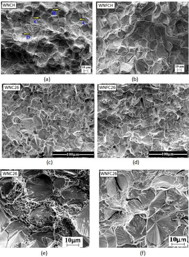
Figure 8 Fractograph of failed tensile specimen (a) WNCH, (b) WNFCH, (c) WNC26, (d) WNFC26, (e) high magnification image of WNC26 and (f) high magnification image of WNFC26. Fracture modes are shown by arrows: A= transgranular cleavage, B= W-matrix separation, C=matrix failure and D=intergranular (W-W) failure.
Limited impact tests were carried out. The impact toughness values of the alloys in final swaged (26 mm) condition are listed in Table 7. WNFC alloy exhibits superior impact toughness compared to WNC alloy. Fracture surfaces of impact tested samples of both the alloys are shown in Figs. 9a-c. Similar to tensile fractographs, in both WNC and WNFC alloys, fracture is predominantly transgranular and consists of tungsten cleavage and matrix rupture. Tungsten-matrix interface failure and tungsten-tungsten decohesion are rarely observed.
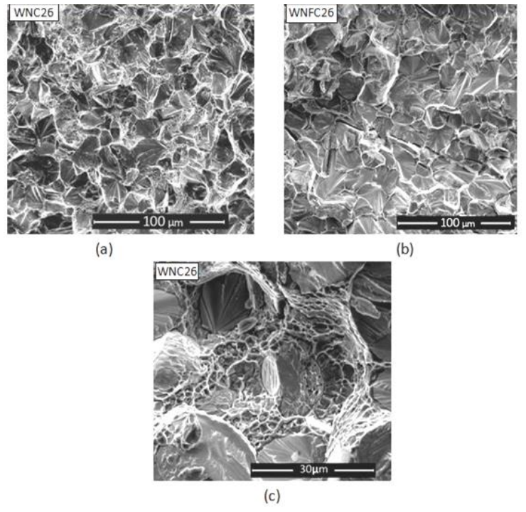
Figure 9 Fractography of failed impact specimens (a)WNC26, (b) WNFC26 and (c) dimples corresponding to matrix failure in WNC26 at high magnification.
Slip line images of compression tested samples of WNC alloy (heat treated condition, A+D) are shown in Fig. 10a and b. While tungsten particles show coarsely spaced and wavy slip bands (Fig.10a), finely spaced linear bands that interact with the fine tungsten precipitates are found in the matrix phase (Fig.10b). This is also observed in TEM images of the deformed sample where interaction of slip bands with tungsten precipitates is clearly discernible (Fig. 10c). Fig. 10d shows the presence of stacking faults in the vicinity of fine precipitates.
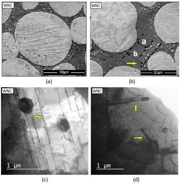
Figure 10 TEM images showing slip lines after compression test (2.8% strained) in WNC (a) slip lines in Wp phase, (b) slip lines in the matrix phase obstructed by fine Ws precipitates, slip line length, a= 7.1 µm and mean free path, b= 11.5 µm, (c) interaction of dislocations and slip bands (edge on) with fine tungsten particles and (d) stacking faults in the matrix phase.
4. Discussion
4.1. Microstructure
Microprobe data clearly show that the primary W particles are relatively purer with W content exceeding 99%, which suggests that the other alloying elements such as Ni, Fe and Co have limited solubility. This is consistent with the binary phase diagrams of W-Ni, W-Co and W-Fe (Okamoto, 1991). The maximum solubility of Ni, Co and Fe are 0.1, 0.3and 0.8 wt% (Okamoto, 1991) respectively. On the other hand the matrix phase is a concentrated solid solution of Ni, Fe and Co. In fact all alloying additions primarily partition to the matrix phase. Substantial dissolution of W is also observed in the matrix phase. While the matrix phase of WNFC alloy (in final swaging condition) contains 29% wt. dissolved W, that of WNC alloy contains 40% wt. W. The maximum solubility of W in Ni which is a major constituent in the matrix phase is 42 wt. % (Okamoto, 1991). Lower solubility of W in WNFC alloy is ascribed to the presence of Fe. Fig. 11 shows W as a function of Fe content in the solid solution of the matrix phase with the solubility of W in FCC ( phase superimposed as per a ternary isotherm (Raghavan, 1994).
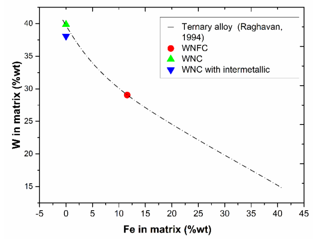
Figure 11 Solubility of W in matrix phase of a ternary alloy (Raghavan, 1994) superimposed with present alloys datapoints: WNFC, WNC and WNC with intermetallics.
As the Fe content in the matrix phase increases, W content decreases. Upon superimposing experimental values with the phase diagram data, it is observed that the W and Fe content of the matrix phase in WNC and WNFC alloys follow the overall trend. Additionally, the combined Fe plus W content in the matrix phase of WNFC alloy is 41 wt % which is close to the W content (40 wt. %) in the matrix phase of WNC alloy. Thus, it is clear that Fe drives out W from the matrix phase thereby reducing its solubility. Now, W content in matrix plays a strong role in the microstructure and therefore mechanical properties, which is elaborated in subsequent sections.
Based on the Ostwald ripening mechanism during liquid phase sintering of heavy alloys, German (1985) have proposed following power law equation for the growth of W particles during liquid phase sintering.
Where G is the grain size as a function of time (t), Go is the initial grain size and the parameter K is a material constant given by Voorhees and Glicksman (1984) as follows:
g is geometric constant, Ds diffusivity of W in the matrix/liquid phase, C the solubility of W in the liquid phase, V the atomic volume, S the solid-liquid interface energy, k Boltzmann’s constant, T the absolute temperature and f is the volume fraction of solid.
The equation suggests that the grain size of the alloy would scale up with the solubility of W in the liquid phase, which can be determined from the composition of the matrix phase. This is further corroborated by Panchal and Nandy (2018) who has investigated the effect of Ni/Fe ratio on microstructure of ternary heavy alloys and shown a clear dependence of W grain size on the W content in the matrix phase. Since the W content of WNC alloy is substantial higher as compared to WNFC alloy, one would have expected relatively coarser grain size in case of WNC alloy. Instead it is finer, although marginally. Thus W content in the matrix is not able to explain the grain size of primary W particles in the alloys investigated given that the sintering time-temperature remains same for both the alloys. Another parameter in equation 3 that may influence grain size is Ds, the diffusivity. The magnitude of this term may be lower in the presence of higher Co as well as W, which may then explain the reduction in grain size. The effect of Co in reducing the interfacial energy between W-matrix which in turn suppresses Ostwald ripening kinetics has also been reported (Stuitje et al., 1995).
Precipitation of intermetallic following heat treatment at low temperature (850 °C) is an important step towards obtaining fine W particles (Ws). Stuitje et al. (1995) have reported that during an intermediate heat treatment (800-1050°C), an intermetallic phase precipitates in the matrix phase and this has been recently identified as Co2W type by Sarkar et al. (2019). The intermetallic phase dissolves at higher temperature solution treatment (1100-1200°C) leaving behind fine W particles (Ws). Subsequent cycle leads to additional intermetallic precipitation as the matrix draws W from primary W particles and the intermetallic on re-dissolution at higher temperature yields additional W precipitation. Thus, the volume fraction of W precipitates increases with no. of heat treatment cycles.
While WNC alloy shows the presence of intermetallic phase following low heat treatment at 850°C, no such precipitation is observed in WNFC alloy with same heat treatment (Fig. 4a and b). The tendency for precipitation of intermetallic which is W rich (47%) is possibly influenced by the W content in the matrix (Table 4). The absence of the intermetallic precipitate in the matrix phase of WNFC alloy is related to substantially lower W content (29 % as opposed to 40% in WNC alloy) and since the intermetallic is not present, fine W precipitates are not observed at higher solution treatment temperature. Therefore, WNFC alloy is given a standard heat treatment (C+D) that results in matrix without W precipitates, which is usually observed in W-Ni-Fe alloys (Song et al., 1997). On the other hand, WNC alloy is subjected to cyclic treatment (A) followed by 1150°C/WQ (D) in order to get secondary fine tungsten precipitates (Ws) in the matrix phase. The presence of jagged periphery of primary W particles is also seen Fig. 5b. This has also been shown by Stuitje et al. (1995) in their patent in form of a schematic. The fact that the intermetallic precipitates on W-matrix interface points towards a peritectiod reaction which may be written as follows:
The jagged nature of interface indicates non uniform growth of the peritectoid collar that needs to be understood in detail. The presence for jagged interface is significant because it has been reported by Song et al. (1997) that microstructure with undulated/jagged W-matrix interface leads to improved ballistic performance of these alloys.
Other vital microstructural parameters such as contiguity and matrix volume fraction have been determined after (i) heat treatment and (ii) after final swaging (Table 3). Though swaging is expected to alter the grain size and contiguity, vacuum and nitrogen heat treatment is not expected to result in any significant change in any of these parameters. This is mainly due to the relatively slower solid state diffusion that occurs during heat treatment as compared to liquid phase sintering. In both the alloys, after final swaging, cross sectional grain size decreases substantially, from about 20 µm to 15 µm (Table 3). This is due to swaging deformation that results in elongation of tungsten grains along the swaging direction with concomitant decrease in the cross sectional area (Fig. 6). The volume fraction of the matrix does not change significantly, varying within 21-28% in both vacuum heat treated and second swaged conditions. The scatter in the matrix volume fraction is possibly due to microstructural variation which is expected in powder metallurgy products. Additionally, liquid phase sintering results in settling down and clustering of tungsten particles due to gravitational force thereby resulting in microstructural in-homogeneity (Upadhyaya et al., 2007)
4.2. Mechanical Behaviour
The early generation tungsten heavy alloys based on W-Ni-Fe comprised primary round W particles (Wp) and a matrix phase that had a single-phase microstructure (FCC solid solution). The role of this matrix phase was to aid liquid phase sintering, bind the spherical tungsten particles (Wp) together and impart ductility to the in situ two phase composite. In order to improve the ballistic performance of heavy alloy long rods, modification of alloy chemistry was attempted for enhancement of mechanical properties, which led to incorporation of Co in W-Ni-Fe alloys. Simultaneously, attempts were also made to modify the microstructure; therefore precipitation of a second phase in matrix has been part of this effort in order to realize superior mechanical properties. Possibility of precipitation of a ductile phase in the matrix of 90W-5Ni-5Fe was first reported by Posthill and Edmonds (1986) who showed the presence of ductile FCC phase on W-matrix interface. It was suggested that the presence of such phase would lead to enhancement of mechanical properties especially elongation in heavy alloys. This work was not pursued further possibly because the property enhancement was not substantial. Therefore, the matrix phase of W-Ni-Fe and W-N-Fe-Co alloys has remained single phase. On the other hand, fine W precipitate in Ni-Co matrix was reported by Couque et al. (1992) Ductility as high as 15% was obtained with enhanced strength values as compared to W-Ni-Fe alloys (Cai et al., 1995). Stuitje et al. (1995), in a patent, reported mechanical properties of two alloys (91W-6Ni-3Co and 93W-6Ni-1Fe) in heat treated and heat treated plus swaged conditions that clearly showed the superiority of W-Ni-Co alloys in terms of mechanical properties. A suitable two stage heat treatment was employed to tailor the distribution of fine W precipitates in the matrix phase. Similar results have been recently shown by Skoczylas et al. (2019) in W-Ni-Co and W-Ni-Co-Fe alloys based on 91% W. W-Ni-Co alloys showed enhanced strength, % elongation to failure and impact toughness as compared to W-Ni-Co-Fe alloys.
In the present study, a detailed study of microstructure and mechanical properties have been undertaken in two alloys, 90W-7Ni-3Co (WNC alloy) and 89.6W-6.2Ni-1.8Fe-2.4Co (WNFC alloy). The microhardness values of tungsten particles (Wp) in both the alloys are significantly higher than those of the matrix. Similar observations have been made by Katavic and Odanovic (2005) who evaluated microhardness of W particles and matrix phase in 92.5W-5Ni-2.5Fe alloys with and without Co addition. This is expected since W with bcc structure is stronger than the FCC solid solution of the matrix phase, which is attributed to Peierl’s deformation mechanism in BCC as opposed to a forest mechanism in FCC phase (Frost & Ashby, 1982) The matrix phase of WNC alloy has higher hardness as compared to that in the WNFC alloy. This will be elaborated in subsequent paragraphs.
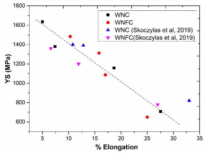
True stress- plastic strain curves (Fig. 7) show that the alloys in heat treated condition exhibit higher elongation and lower strength values (also listed in Table 6a and 6b) as compared to heat treated plus swaged. With increasing swaging deformation while the strength increases, % elongation to failure decreases. Figure 12 shows a plot of yield strength versus ductility with data of Skoczylas et al. (2019) superimposed. Increase in strength at the expense of ductility is attributed to increasing dislocation density as a result of swaging deformation imparted that is in the range of 11-53 % (Das et al., 2014).
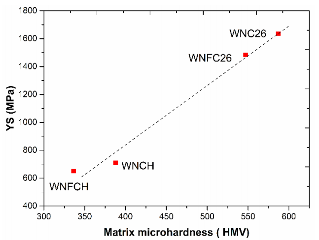
For a given thermomechanical treatment (that includes both heat treatment and heat treatment plus swaging), WNC alloy always exhibits higher strength as compared to WNFC alloy. The difference in yield strength ranges from 60-150 MPa approximately. Skoczylas et al. (2019), who carried out a similar work on W-Ni-Co and W-Ni-Fe-Co alloys reported an increase of 40-190 MPa depending upon whether the specimen is heat treated or heat treated plus swaged. It has been shown earlier that the matrix phase is considerably softer; therefore the slip deformation is expected to initiate in the matrix phase. Thus, the yield strength of the two phase aggregate will depend on the strength of the matrix phase that in turn may be related to the microhardness of the matrix phase. Ashutosh et al. (2018) while studying the effect of Ni/Fe ratio have shown that both yield strength and tensile strength scale up with microhardness of the matrix phase. The yield strength values evaluated in heat treated and heat treated plus swaged conditions have been plotted against matrix microhardness in Fig. 13. A linear correlation is seen pointing towards the influence of the softer matrix phase on the strength of heavy alloys. This in turn provides an explanation for higher strength of WNC alloy as compared to WNFC alloy. The reason higher microhardness and therefore higher strength of WNC alloy as compared to WNFC alloy may be two-fold: (a) the presence of second phase that is micron size W precipitates (Ws) and (b) higher dissolved W content in the FCC matrix.
Micron-sized precipitates appear to obstruct the slip traces (Fig. 10b) which would lead to refinement in slip line length thereby explaining the increase in strength of the matrix. However, the refinement appears to be marginal as seen in Fig. 10b. The precipitate spacing, ‘a’ is 7.1 µm whereas the mean free path (that is the distance between the periphery of primary Wp particles) in the absence of precipitates, ‘b’ is 11.5 µm as shown in Fig. 10b. A recent work by Prabhu et al. (2019) shows that the presence of precipitate in W-Ni-Co alloy results in marginal increase in strength by 50 MPa whereas in the present study,additional strengthening as high as 150 MPa has been observed in WNC alloy as compared to WNFC alloy. Kumari et al. (2017) studied a series of heavy alloys based on 90% tungsten and evaluated the role of dissolved W on the yield strength of alloys that underwent similar thermo-mechanical processing. The data points of present alloys are superimposed in their plot in Fig. 14. It can be seen both these points lie on the overall trend line, which suggests that the strengthening in WNC alloy as compared to WNFC alloy may be explained by the enhanced W solubility. It has been reported (Stuitje et al., 1995) that the stacking fault energy decreases with W addition in the matrix phase, which may explain additional strengthening observed in WNC alloy. However, detailed study needs to be undertaken in order to understand the mechanism of strengthening in the matrix phase.
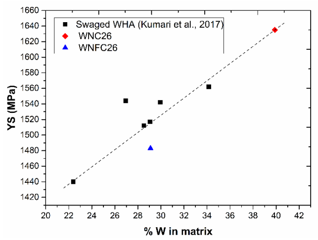
Figure 14 Plot showing variation in 0.2% YS of alloys with respect to dissolved W in their matrix phase.
The primary difference between WNC and WNFC alloys as regards fractographs (Fig. 8, 9) is the failure of the matrix phase. While micro-void coalescence is seen in WNC alloy (8e, 9c) in both heat treated and heat treated plus swaged alloys, the failure of the matrix in WNFC alloy is by shear lip (Fig. 8f). Microvoids as opposed to shear lip is because of the presence of undeformable Ws preciptates in the matrix phase of WNC alloy and this possibly explains lower elongation values of WNC alloy especially at higher swaging deformation. Lower impact value of WNC alloy as compared to WNFC alloy (Table 7) may also be explained by a similar argument. Thus it appears the presence of W precipitates in the matrix phase would result in reduction of ductility and impact toughness especially at higher swaging deformation.
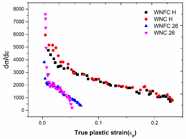
The log-log plots of true stress versus true plastic strain in heat treated and swaged conditions are shown in Fig. 15. Two slope behaviour is observed in heat treated (WNC-H and WNFC-H) and first swaged (WNC-34 and WNFC-34) conditions. These regimes are not clearly demarcated for higher swaging conditions (WNC-30, 26and WNFC-30, 26). The slopes of the curves in the heat treated conditions are higher as compared to the swaged conditions, which appears to be consistent with the steeper stress-strain curves. The two slope behaviour has been explained by Das et al. (2014) and Panchal et al. (2020) in their work on W-Ni-Fe and W-Ni-Fe-Co alloys. By conducting a study on slip line traces, Das et al. (2014) have shown that the regime I corresponds to the deformation of the softer matrix phase and regime II is the manifestation of deformation of two phase aggregate at higher plastic deformation. The regimes are not very clear in as swaged conditions possibly because both W and the matrix phase are strain hardened already during swaging and participate in macroscopic deformation right from the start.The rate of strain hardening vs. plastic strain plots for heat treated (WNCH and WNFCH) and swaged (WNC-26 and WNFC-26) conditions are shown in Fig. 16.Three regimes are observed except WNFC-26 that shows two regimes. BCC materials such as Ta (Chen & Gray, 1996) show two regimes: (1) regime I, where the rate of strain hardening falls rapidly, (2) regime II where it reaches plateau. This is attributed to two competing mechanisms: (1) hardening due to accumulation of dislocations and (2) recovery of the substructure leading to softening. This corresponds to Stage III of single crystal deformation (Dieter, 1988). Similar behavior is noticed in FCC materials with high stacking fault energy such as Cu (Sinclair et al., 2006), Complexities arise in FCC with low stacking fault energy because of nucleation of twin during deformation. El-Danaf et al. (2001) have shown that the strain hardening rate as a function of strain shows four distinct regimes: regime I corresponding to stage III deformation of single crystal, a plateau of regime II associated with nucleation of twins, regime III due to decrease in the nucleation rate of twins and regime IV corresponding to twinintersection. The matrix phase of the alloys investigated here possesses low stacking fault energy due to the presence of W and Co in Ni solid solution (Stuitje et al., 1995). This is further corroborated by the presence of stacking faults in the matrix phase of WNC alloy (Fig. 10 c), however the regime III is considerably shrunk and regime IV is absent possibly due to the fact that the matrix volume fraction is relatively lower and we are observing a two phase deformation especially at higher strains.
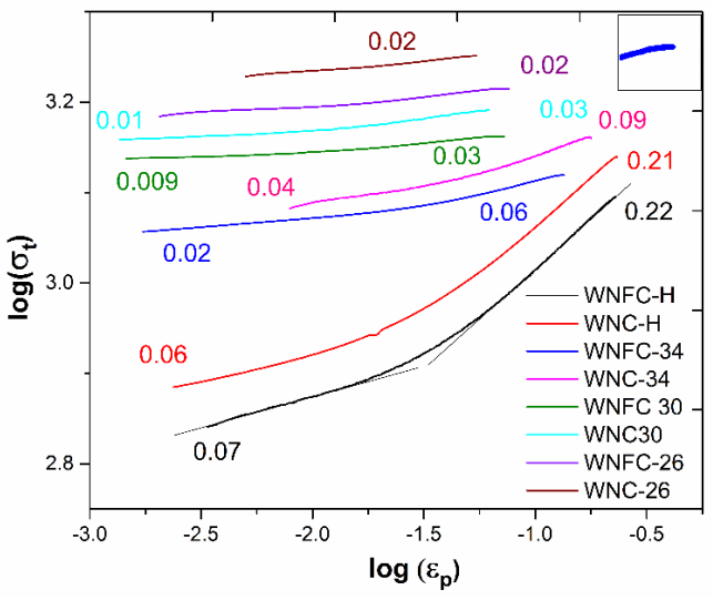
Figure 15 Log-log plots of true stress versus true strain of heat treated and swaged alloys. Respective work hardening exponents are mentioned along the curves.
5. Conclusions
W-Ni-Co and W-Ni-Fe-Co heavy alloys based on 90%W were studied for microstructure and mechanical properties. Salient conclusions are as follows:
1. The microstructures of both the alloys consist of round tungsten particles bound by a continuous matrix phase. The matrix of the W-Ni-Co alloy (subjected to a cyclic treatment) contains a dispersion of fine W precipitates in an FCC solid solution of Ni, W and Co. On the other hand, the matrix of W-Ni-Fe-Co is devoid of any precipitates even after same cyclic heat treatment.
2. The presence of fine W precipitates in the matrix of W-Ni-Co alloy is a result of a cyclic treatment which initially results in the formation of W-rich intermetallic and then the intermetallic dissolves at higher temperature leaving behind fine W precipitates.
3. The formation of W rich intermetallic is favoured in WNC alloy since the matrix is relatively richer in W due to enhanced solubility of W in the matrix in the absence of Fe.
4. The yield and tensile strength of WNC alloy are higher than those of WNFC alloy for all thermo-mechanical processing conditions.
5. The ductility and impact toughness values are marginally lower for WNC alloy than WNFC alloy especially for higher swaged conditions. This is attributed to the presence of undeformable Ws precipitates in matrix phase resulting in stress concentration and crack/void nucleation at Ws-matrix interface.
6. Superior strength values achieved in WNC alloy as compared to WNFC alloy is attributed to enhanced solubility of Win the matrix.

