


 nueva página del texto (beta)
 Inglés (pdf)
 Artículo en XML
 Referencias del artículo
 Enviar artículo por email
 Citado por SciELO
  Similares en
SciELO
Similares en
SciELO 
 Permalink
1. Introduction
1.1. The freeze casting technique
Freeze casting is a material processing technique used to fabricate well defined, oriented and controlled porous structures in ceramics, metals, polymers and composites. Such advanced materials have numerous applications such as biomaterials, catalysts, drug delivery systems, battery electrodes, among other ones (Deville, 2008; 2010; Fukasawa et al., 2001; Huang et al., 2015; Lee et al., 2007; Scotti & Dunand, 2018).
In order to exploit the full potential of the technique, the freezing step must be well controlled, since the density, size and shape of the pores determined in this step. Freezing is preceded by material synthesis and slurry preparation, if necessary, and followed by sublimation and sintering, if necessary (Figure 1).
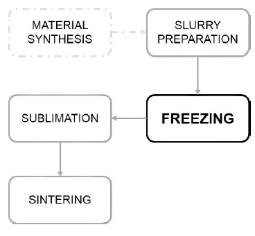
Figure 2 shows a slurry submitted to a temperature gradient which induces nucleation and growth of ice in the direction of the temperature gradient (Araki & Halloran, 2005a; 2005b; Choi et al., 2012; Dong et al., 2016).
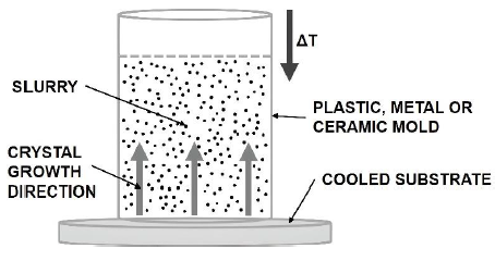
Crystal growth compresses the slurry particles between the crystals. The final structure depends on the nature of the solvent, on the particle distribution in the slurry and on the liquid-solid interaction. This means that the structure is strongly influenced by the freezing conditions, highlighting the importance of controlling the cooling rate, time and temperature (Deville, Saiz & Tomsia, 2006; Deville et al., 2006; Rodríguez-Parra et al., 2012; Waschkies et al., 2011).
Some authors describe the process they used to produce porous materials and provide simple schemes of the freezing system as well as the chosen parameters (Araki & Halloran, 2005c; Deville et al., 2007; Du et al., 2018; Hong et al., 2011; Huang et al., 2017; Waschkies et al., 2011; Wegst et al., 2010; Xie et al., 2013). However, there is no complete description of the apparatus and the authors do not show how the equipment can be adapted to a particular application. This work proposes a simple and flexible instrumentation for the freezing step in the production of porous materials. The equipment proposed is of easy construction and low cost.
2. Constructive components
2.1. Cold finger and sample substrate
The freezing unit requires a cold finger, which provides heat transfer from the sample to the cooling element. Metals are good heat conductors, and among them, pure copper (Cu), with k = 385 W/mK at room temperature, is the second best conductor after silver (Ag). At low temperatures, Al is also an excellent conductor. The cold finger should therefore be made of a good and cheap thermal conductor such as Cu or Al. This justifies the choice of a copper cold finger for this project.
A massive electrolytic Cu bar with 25.4 mm in diameter and 500.0 mm long was used as a cold finger. The dimensions were chosen based on the design of bar anchoring in the thermal container that will be described shortly.
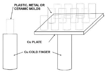
Some researchers place the mold directly over the cold finger (Deville, Saiz & Tomsia, 2006; Du et al., 2018; Huang et al., 2017; Porter et al., 2014; Porter et al., 2016; Waschkies et al., 2011), but in this case, in order to process several samples simultaneously, a square electrolytic Cu plate, 100.0 mm wide and 5.0 mm thick, was positioned above the cold finger, as shown in Figure 3. The maximum temperature difference between the center of the plate in contact with the cold finger and the plate edges is 0.5 K measured with digital infrared thermometer during a test.
The slurry mold may be metallic, ceramic or polymeric and the material choice may affect the crystal growth direction. For instance, in copper molds, nucleation and crystal growth may be both axial and radial since the temperature gradient will be the same for the substrate and mold walls.
Polymeric molds made by polytetrafluoroethylene (PTFE), polyethylene (PE), polypropylene (PP) or polyvinyl chloride (PVC) (Araki & Halloran, 2005c; Deville, 2010; Dong et al., 2016; Hong et al., 2011; Waschkies et al., 2011; Xie et al., 2013) are widely used and these molds provide transversal heat transfer (e.g. thermal conductivity of PVC is 0.21 W/mK at room temperature) because of their lower thermal conductivities compared to cold finger. In addition, the material is affordable and widely available in form of hydraulic pipes.
Other setup possibilities include the use of a double cold finger (Deville et al., 2007; Waschkies et al., 2011), one above and the other below the mold, in order to enhance directional freezing.
2.2. Thermal container
Few authors specify this component, which holds the coolant that may be cold water (Araki & Halloran, 2005c), liquid nitrogen (Choi et al., 2012 Deville et al., 2007; Du et al., 2018; Huang et al., 2017;) or cold ethanol (Fukasawa et al., 2001; Dong et al., 2016). A thermal container with a polypropylene and polyethylene cover was used in this project.
Polystyrene is an excellent thermal insulation material, with thermal conductivity coefficients of k = 0.038 W/mK at room temperature. Polypropylene has a thermal conductivity coefficient of k = 0.25 W/mK. A 30.0 mm thick layer of extruded polystyrene foam and a 0.3 mm thick layer of polypropylene were placed along the entire container wall. The box outer dimensions are 450.0 mm in width, 380.0 mm high and 330.0 mm in depth. The useful volume given by the manufacturer is 32.0 liters.
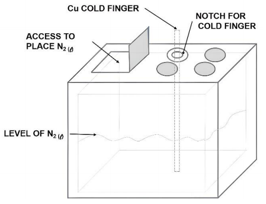
The coolant used in this project was liquid nitrogen with a boiling temperature of 77 K. It was experimentally determined that 15.0 L of liquid nitrogen in the thermal container is the minimum quantity required for the entire cold cycle which will be shortly described. This thermal container is easily found for purchase and it was chosen for its low cost, easy cleaning and adequate thermal properties and a peculiar cover feature. This
feature allows to access the inner part of the container without opening the entire cover (Figure 4), reducing the loss of liquid nitrogen during filling and possible replacement during experiments. Another interesting feature are the notches; in one of them, a circular cut was made for cold finger anchorage.
The coolant used in this project was liquid nitrogen with a boiling temperature of 77 K. It was experimentally determined that 15.0 L of liquid nitrogen in the thermal container is the minimum quantity required for the entire cold cycle which will be shortly described. This thermal container is easily found for purchase and it was chosen for its low cost, easy cleaning and adequate thermal properties and a peculiar cover feature. This feature allows to access the inner part of the container without opening the entire cover (Figure 4), reducing the loss of liquid nitrogen during filling and possible replacement during experiments. Another interesting feature are the notches; in one of them, a circular cut was made for cold finger anchorage.
2.3. Heating element
One heating element was used to control the sample cooling rate. It consists of a coil of 1.0 mm thick wire made of a commercial 80/20 Ni/Cr alloy, known as nichrome, quite common for such application (Green & Clothier, 1988; Nukiyama, 1966; Sears et al., 2017; Talalay et al., 2018; Velders et al., 2018). It was positioned 40.0 mm from the tip of the cold finger, as shown in Figure 5.
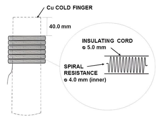
The electrical resistivity of nichrome is ( = 108 x 10-8 Ωm and, considering a nominal power of 200 W and 127 Vac power supply, the calculated length for the wire using Equation (1) was 60.0 m,
where L is wire length and A is wire cross-sectional area. The wire was wound into a 4.0 mm inner diameter coil with approximately 4,600 turns.
The wire was covered with an insulating cord, avoiding contact with the moisture produced during cold finger operation in order to avoid degradation. In this configuration, the wire can reach a temperature of about 350 ºC.
2.4. Temperature sensor
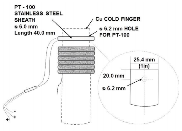
An important component of the freezing unit is the temperature sensor, although some authors do not report its use (Araki & Halloran, 2005c; Choi et al., 2012; Dong et al., 2016; Du et al., 2018; Fukasawa et al., 2001). It can be a thermocouple, a thermostat or a resistance temperature detector (RTD) (Deville et al., 2007; Huang et al., 2017; Rodríguez-Parra et al., 2012; Waschkies et al., 2011; Wegst et al., 2010; Xie et al., 2013). An RTD was used in this project because, although it is more expensive than the other options, because it is more accurate and works over a wider temperature range.
RTDs are wires whose change in electrical resistance is used to determine the temperature. They have high accuracy, low response time, high stability and excellent repeatability (Liptak). They are made in reels and encapsulated in a ceramic bulb, attached to a stainless-steel sheath. They are manufactured in 2, 3 or 4 wire assemblies in order to minimize the voltage drop effects in the connecting wire (ASTM E644-11, 2011; Liptak, 2003). Pt is the most commonly used element in this type of temperature sensor because it has a linear response over a wide temperature range.
A 3-wire 100 Ω (at 273 K) platinum RTD was used in this project. Commercially known as PT-100, it works in a range of 25 K to 1125 K. Its temperature resistance values are described in ASTM E1137/E1137M-08 (2014).
The characteristics of this element are: stainless steel sheath of 0.6 mm diameter and 40.0 mm long, connecting wire 800.0 mm long. This was attached 20.0 mm from the cold finger, into a hole made in the Cu bar, as shown in Figure 6.
2.5. Controller
Although some authors report manual control of the heating element (Rodríguez-Parra et al., 2012; Xie et al., 2013), it would be hard to operate the system described in this work without an automatic controller to monitor and adjust freezing parameters such as cooling rate, time and temperature (Deville et al., 2007; Waschkies et al., 2011; Wegst et al., 2010). The controller used in this project was the COEL® KM5P (Coelamtic Ltda, 2018; 2016). It is possible to work with thermocouples type J, K, S, R, T, PT-100, PT-1000, besides infrared sensors and voltage and current input. According to the manufacturer, it provides total accuracy of ±0.5%. Depending on the thermocouple, this controller operates between -200 °C (73 K) and +1760 °C (2033 K).
2.6. Freezing unit assembly
Assembly of the freezing unit was carried out in the following sequence:
- A 30.0 mm diameter circular hole was cut on the cover of the thermal container.
- A 6.2 mm diameter hole was cut on the Cu bar;
- The Cu bar was attached to the box. A PVC sealing ring was inserted to insure thermal insulation and more stability to the bar;
- The controller was attached to the thermal container. A polypropylene grid was screwed to the wall of the thermal container and the controller was clamped to the grid. In addition to the controller, a circuit breaker (15 A) and a SSR relay were clamped in the same way. The SSR was installed to operate the heater using the controller since the output signal of the controller is 12 Vdc and the heater operates at 127 Vac;
- The heater wire was coiled around the Cu bar;
- The temperature sensor was attached to the Cu bar;
- The electric connections were made as shown in Figure 7. The 9 and 10 controller terminals were connected to the power supply. Terminals 1, 2 and 3 were connected to the RTD. Terminals 7 and 8 provided the output signal for the SSR relay.
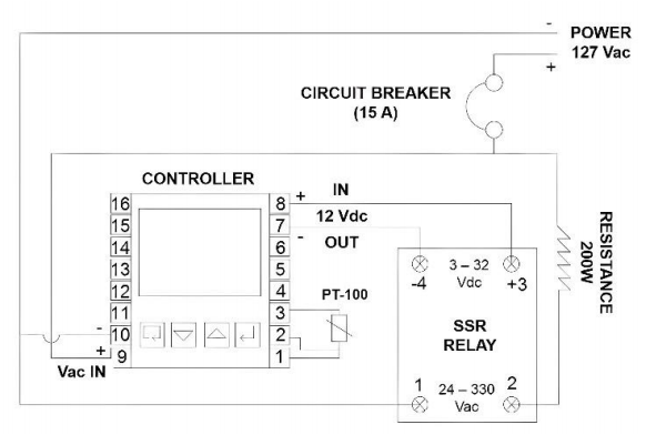
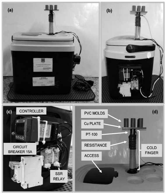
Figure 8 shows the finished freezing unit (a) and (b) and the individual components (c) and (d).
2.7. The freezing unit test and materials characterization results
The developed equipment was used for the series production of advanced porous magnetic ceramics a metallic sample and the tests showed that the system was behaving as projected, as will be described below.
The SEM micrographs of ZnFe2O4, MnFe2O4, CoFe2O4, NiFe2O4, SiO2, Al2O3 and Cu samples produced are shown in Figures 9 and 10. Oriented porous structures, typical architectures produced by the freeze casting technique, were achieved in all samples. The copper sample showed smaller pores larger gaps when compared to the other samples. This feature may be associated to the low freezing temperature used (Liu et. al, 2017). The pores are parallel to the ice growth direction, represented by the red arrows. A FEI Quanta 250 (FEG) microscope was used to acquire the images.
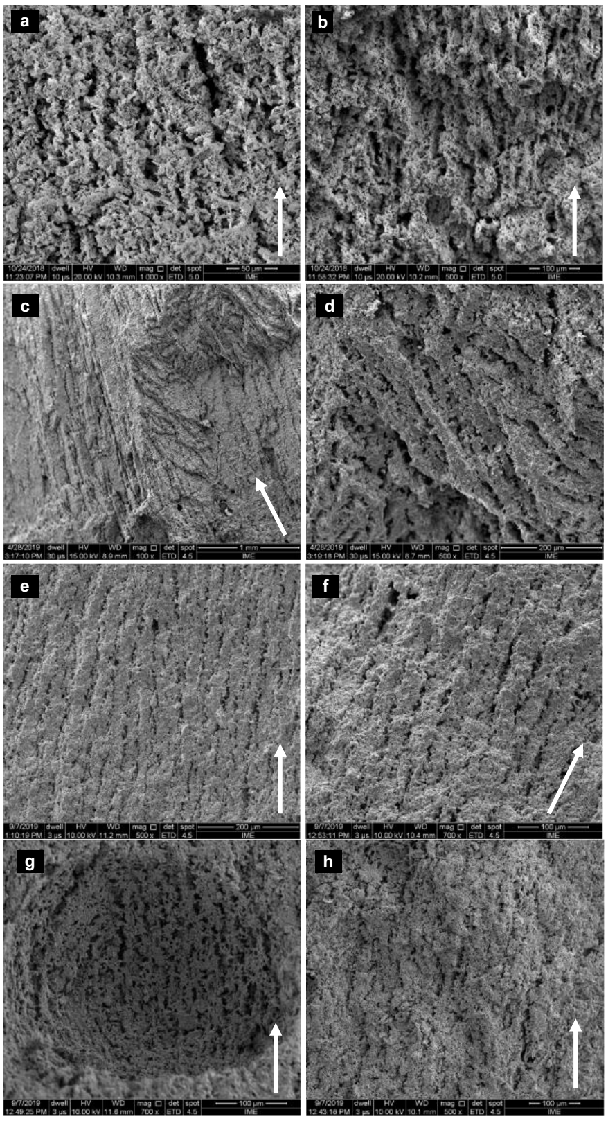
Figure 9 SEM images of a: (a) ZnFe2O4 sample cross section parallel to freezing direction and (b) tilted cross section. (c) MnFe2O4 sample cross section parallel to the freezing direction and (d) sample top view. (e) and (f) CoFe2O4 sample cross section parallel to freezing direction. (g) and (h) NiFe2O4 sample cross section parallel to freezing direction. White arrows show the freezing direction.
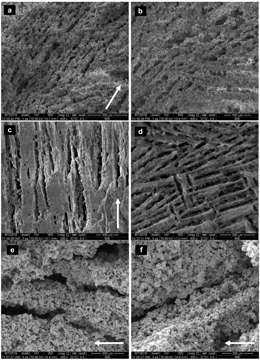
Figure 10 SEM images of a: (a) SiO2 sample cross section parallel to the freezing direction and (b) sample top view. (c) Al2O3 sample cross section parallel to the freezing direction and (d) sample top view. (e) and (f) Cu sample cross section parallel to the freezing direction. White arrows show the freezing direction.
ZnFe2O4, MnFe2O4, CoFe2O4 and NiFe2O4 samples were prepared with 10 wt% of solid in a slurry with distilled water and PEG-4000 (8 wt%), at pH 10.
SiO2 sample was prepared with 30 wt% of solid in a slurry with distilled water and PEG-4000 (8 wt%), at pH 12.
Al2O3 sample was prepared with 30 wt% of solid in a slurry with distilled water and PEG-4000 (8 wt%), at pH 11.
Copper (metallic) sample was prepared with 70 wt% of solid in a slurry with distilled water and PEG-4000 (8 wt%), at pH 10.
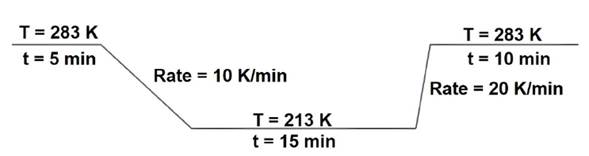
All samples were frozen in a PVC mold, with a cooling rate of (10 K/min down to 213 K, as outlined in Figure 11, and were randomly placed in the Cu plate. For solvent (distilled water) sublimation, all samples were kept under 0.004 Bar pressure for 8 hours and sintered at 1573 K for 1 h as previously reported (dos Santos Aguilera et al., 2018) for ZnFe2O4, MnFe2O4, CoFe2O4 and NiFe2O4 samples, 1553 K for SiO2, 1823 K for Al2O3 and 1083 K for Cu.
These tests indicated that the thermal container yielded a good performance, with a small loss of cooling liquid. The volume (15 L) was adequate for handling and met the required cooling demand. The system worked properly on volumes above 10 liters.
The temperature variation, measured by infrared thermometer, between the center of the copper plate (50.0 mm x 50.0 mm) and the edge regions was about 0.5 K. Observing the microstructures of the samples randomly arranged on the plate it is possible to observe a well-controlled, directional structure formation in all areas of the plate. The measured temperatures were in accordance to PT-100 indication on the controller display.
The temperature sensor and the heating element were tested with and without a sample for freezing rates between 2 K/min and 20 K/min, in steps of 1 K/min and measured by infrared thermometry. Using PT-100 thermal sensor the stability in the measurement was checked between 73 K and 2033 K. A stabilization temperature may be employed for consecutive experiments, for instance, above 283 K, for the end and start of a new thermal cycle. Coolant replacements during the thermal cycle change the cooling rates; for this reason, replacement must be done at the end of the cycle or in the beginning of the next one.
Improvements may be made in the described equipment, such as: changes in quantity and dimensions of samples to be frozen at the same time; changes in cooling rates for obtaining a desired microstructure via slower or faster cooling rates; changing the coolant as well as settling cooling capacity; to apply magnetic fields to control pore orientation, or using two cold fingers at same time. This last change would require a second apparatus so that the sample could be placed between the two cold fingers. The proposed apparatus has several advantages over those already reported: it is compact, portable and may be easily assembled by everyone interested in related studies.
3. Conclusions
A freezing unit dedicated to freeze casting was developed using low cost and easily available components. All components were purchased separately and assembled because there is no available similar commercially equipment.
Tests with and without samples were successfully carried out. The structure formation was confirmed in all evaluated materials. For porous materials production investigations, the results were satisfactory.
Porous microarchitectures were achieved, applying the process in colloidal suspensions of nanoparticles of ZnFe2O4, MnFe2O4, CoFe2O4 and NiFe2O4 and micrometric particles of SiO2, Al2O3 and Cu. It was possible to observe the complex structure formed by scanning electron microscopy.
The proposed setup can be readily adapted for other sample sizes and shapes, limited only by the sizes of the cold finger and the copper plate. The use of a programmable controller increases the system accuracy and flexibility, since the cooling rate is easily changed and the use of PT-100 as a thermal sensor ensures good accuracy.
This setup had a patent application filed in Brazil, under case number BR 20 2019 027424 2 on December 19, 2019.

