SciELO - Scientific Electronic Library Online

 
vol.20 número3Development of a community-scale autonomous water purifier (AWP) prototype to remove heavy metalsRepetitive corrugation and straightening effect on the microstructure, crystallographic texture and electrochemical behavior for the Al-7075 alloy índice de autoresíndice de materiabúsqueda de artículos
Home Pagelista alfabética de revistas  

Servicios Personalizados

Revista

Articulo

Indicadores

Links relacionados

  • No hay artículos similaresSimilares en SciELO

Compartir


Journal of applied research and technology

versión On-line ISSN 2448-6736versión impresa ISSN 1665-6423

J. appl. res. technol vol.20 no.3 Ciudad de México jun. 2022  Epub 17-Feb-2023

https://doi.org/10.22201/icat.24486736e.2022.20.3.1637 

Articles

Circularly polarized ultra wideband antenna with question mark-shaped patch for ground penetrating radar applications

Abdelhalim Chaabanea  * 

Mohammed Guerrouia 

a Laboratoire des Télécommunications, Département d'Electronique et Télécommunications, Faculté des Sciences et de la Technologie, Université 8 Mai 1945 Guelma, BP 401, Guelma 24000, Algeria


Abstract

A novel Circularly Polarized (CP) Ultra Wideband (UWB) antenna for Ground Penetrating Radar (GPR) applications is presented and discussed in this paper. The proposed antenna is constructed by a question mark-shaped radiating patch and a truncated ground plane. A prototype of the designed antenna is fabricated on the FR4-substrate with an overall volume of 0.7λ0×0.793λ0×0.035λ0 at 7 GHz. The simulated results show that the designed antenna has an Impedance Bandwidth (IBW) ranging from 3.14 GHz to 11.88 GHz (116.38%). The CP feature is analyzed and discussed confirming that the antenna maintains a CP radiation characteristic in a broadband with a 3-dB Axial Ratio Bandwidth (ARBW) ranging from 4.13 GHz to 9.28 GHz (76.81%). The measurements were done by utilizing a well calibrated R&S®ZNB Vector Network Analyzer indicating that the fabricated prototype has an IBW nearly ranging from 3.47 GHz to 12.11 GHz (110.91%). The results are favorable that ensure the usefulness of this antenna for GPR applications.

Keywords: Ultra wideband (UWB) antenna; impedance bandwidth (IBW); axial ratio bandwidth (ARBW); circular polarization; ground penetrating radar (GPR) antenna

1. Introduction

The Ground Penetrating Radar (GPR) is a non-damaging geophysical method that is used in several disciplines for investigating sub-surfaces. By using electromagnetic waves, GPR systems detect changes in the properties of the penetrated surfaces and so concealed objects can be detected. The antenna is considered as an important hardware component in the GPR systems since it generates the necessary electromagnetic waves. Hence, the penetration and the detection capabilities of the GPR systems are decided principally by the performances of the antenna and by the radiated electromagnetic waves (Chaabane & Guerroui, 2021; Grinč, 2015; Guerroui et al., 2021; Hendevari et al., 2018; Raza et al., 2019). The circularly polarized (CP) feature is needed for the GPR antennas since the performances of the GPR systems depend mainly on the reflected waves containing the indications (Takach et al., 2016). In this context, several GPR antennas have been reported in recent literature such as those proposed in (Chaabane & Babouri, 2019; Elsheakh & Abdallah, 2019; Joula et al., 2018; Kundu et al., 2018; Kundu, 2018; Liu et al., 2019; Li et al., 2016; Mohanna et al., 2018; Raza et al., 2020) but only few have CP characteristic like those presented in (Elsaid et al., 2019; Liu et al., 2015; Raychaudhuri et al., 2016, Stillman et al., 2016). Unfortunately, the CP GPR antennas available in the literature have complex structures and/or have enormous voluminous size. Thus, there is a strong need to design easy-to-fabricate and inexpensive GPR antennas that have a high competence of the penetration and of the investigation.

In this study, a compact CP UWB antenna is proposed for GPR applications. The designed antenna is formed by a question mark-shaped radiating patch and a truncated ground plane. The proposed antenna was simulated and optimized by employing the software CST Microwave StudioTM (Computer Simulation Technology, 2016). A prototype for the antenna is fabricated and measured by using R&S®ZNB Vector Network Analyzer. Encouraging results were achieved within the interesting bandwidth which indicate the aptitude of the antenna to work as a GPR antenna.

2. Antenna design and results

Both the front view and the back view of the proposed CP UWB antenna are schematically depicted in the Fig. 1. The antenna design development steps are given in the Fig. 2. The antenna is built on a 1.5-mm-thick FR-4 epoxy with an area of 0.7λ0×0.793λ0 at 7 GHz and a relative permittivity of 4.4. The designed antenna is constructed by a question mark-shaped radiating patch and a truncated ground plane. The goal of the chosen shapes for the radiating patch and for the ground plane is mainly to more enlarge the IBW. Other advantages for the chosen shapes are that the weight of the antenna and the conduction losses can be reduced. The optimized dimensions for the designed antenna are as follows: LS=30 mm, Lg=8 mm, LP=19.5 mm, L1=1.92 mm, L2=5.38 mm, L3=1.58 mm, L4=6 mm, L5=5.2 mm, L6=3.85 mm, L7=3.5 mm, L8=3.85 mm, L9=6.25 mm, L10=1.35 mm, L11=12.4 mm, WS=34 mm, WP=18.6 mm, W1=3.26 mm, W2=1.6 mm, W3=2.3 mm, W4=2.79 mm, W5=6 mm, W6=5.2 mm, W7=3.5 mm, W8=5.8 mm, W9=1.6 mm, W10=2.6 mm, W11=9.8 mm.

Figure 1 Detailed configuration of the proposed CP UWB antenna, (a) front view, (b) back view. 

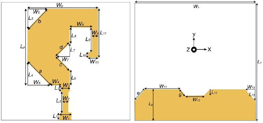
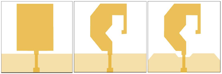
Figure 2 Antenna structure evolution during the design steps, (a) Antenna A, (b) Antenna B, (c) Antenna C. 

Fig. 3 shows that the IBW and the impedance matching of the designed antenna are highly improved by modifying the shape of the radiator from the rectangular shape to a question mark shape and by cutting the metal from the truncated ground plane; approximately an enhancement of around 81.51% for the IBW is achieved. Fig. 4 indicates that the CP characteristic is introduced by the use of a question mark-shaped patch; an axial ratio bandwidth (ARBW) of about 73.7% is achieved. This ARBW is further enhanced by eliminating metal from the truncated ground plane; the attained ARBW is approximately around 76.81%.

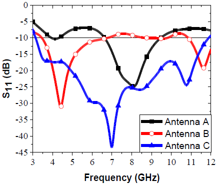
Figure 3 Reflection coefficient comparison of the designed antenna with those of the initial antennas. 

Figure 4 Comparison of the axial ratio of the designed antenna with those of the initial antennas. 

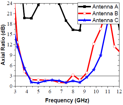
Fig. 5 shows that the designed antenna has a good input impedance characteristic within the operating bandwidth which confirms the well adaptation of the antenna. The real part of the input impedance is nearly varying around 50 ohms value while the imaginary part is nearly around zero value. To understand the generation of the circularly polarized radiations, the current distributions on the surface of the radiating patch and on the surface of the truncated ground plane at the frequency 7 GHz for different phases (0°, 90°, 180°, 270°) are depicted in Fig. 6. The principle direction of the current is along the +X-direction for the phase 0° and it is in the opposite direction (-X-direction) for the phase 180°. Besides, the principle direction of the current is along the -Y -direction for the phase 90° and it is in the opposite direction (+Y-direction) for the phase 270°. Thereby, as the phase augments in time, the main current surface in the azimuth plane of the antenna rotates in clockwise trend which shows a left-handed circularly polarized in the direction of propagation.

Figure 5 Real and imaginary impedance. 

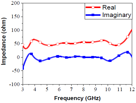
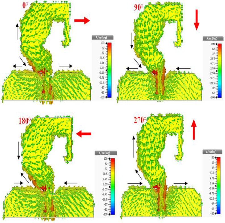
Figure 6 Current distribution on the surface of the antenna at the frequency 7 GHz for different phases. 

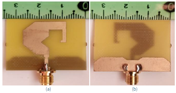
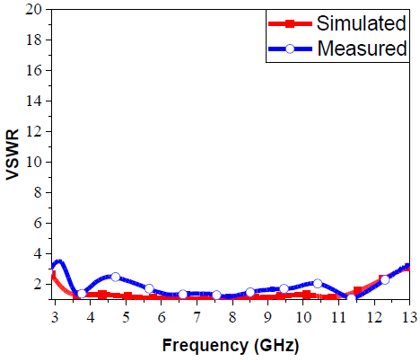
A fabricated antenna based on the optimized parameters was realized by using a LPKF S103 laser printer. A photo of the fabricated prototype is presented in Fig. 7. The working frequency band of the fabricated prototype was measured by utilizing R&S®ZNB Vector Network Analyzer. It is observed that the experimental result is in a good agreement with the simulated one and the UWB feature is proved. Fig. 8 indicates that the fabricated antenna works in a wide bandwidth ranging nearly from 3.47 GHz to 12.11GHz (110.91%) with a feeble peak of about 2.5 at 4.51GHz which may be attributed to the intolerance of the connector and/or of the soldering thus to the losses in the port of the connection.

Figure 7 Fabricated prototype for the designed CP UWB antenna, (a) front view, (b) back view. 

Figure 8 Measured and simulated working frequency band of the proposed antenna. 

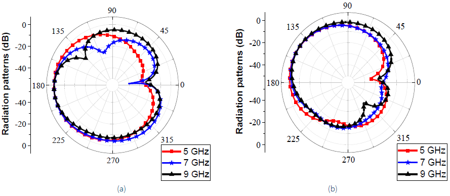
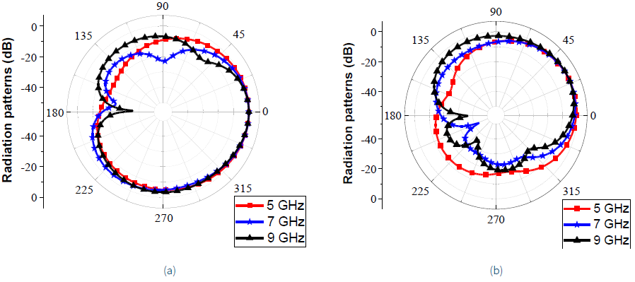
The simulated right-handed circularly polarized (RHCP) and left-handed circularly polarized (LHCP) far-field radiation patterns of the antenna in xz- and yz-planes at 5 GHz, 7 GHz, and 9 GHz are depicted and compared in Fig. 9 and 10, respectively. The minor inclinations of the radiation patterns are due to asymmetric geometry of the designed antenna. It is confirmed that the designed antenna radiates LHCP in the direction of the propagation of the antenna (+z-direction) and RHCP in the reverse direction (−z-direction); the opposite circular polarization is due to the type of this antenna that has bidirectional radiation patterns.

Figure 9 RHCP patterns at different frequencies within the CP band, (a) xz-plane, (b) yz-plane. 

Figure 10 LHCP patterns at different frequencies within the CP band, (a) xz-plane, (b) yz-plane. 

The simulated antenna gain and antenna radiation efficiency are presented in Fig. 11. It shows that the antenna exhibits reasonable values of the gain ranging almost between 3.17 dBi and 6 dBi within the operating bandwidth; the achieved values are better than the ones obtained in (Hosain et al., 2020). Moreover, high radiation efficiency values are achieved which are almost over than 80% within the working bandwidth; these values are better than the ones presented in (Saeidi et al., 2019). A comparison between the proposed antenna and some recently published CP antennas is presented in Table 1. It indicates that the characteristics of the proposed structure are better or comparable to those of some previous works

Figure 11 Gain and radiation efficiency achieved by the designed antenna. 

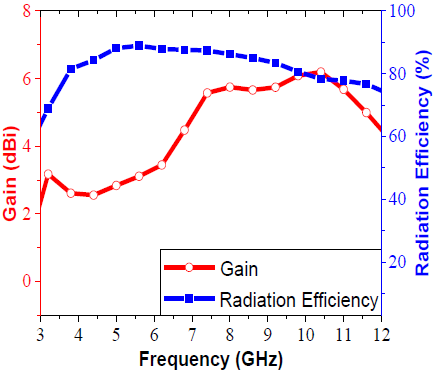
Table 1 A comparative analysis between the proposed antenna and some recently published CP antennas. 

Antennas Substrate Sizes (mm3) ARBW IBW
Pan et al. 2018 FR4 80×80×1.6 0.91 GHz - 0.97 GHz (6.4%) 0.894 GHz - 1.03 GHz (14.1%)
Verma et al. 2020 FR4 60×60×13.45 3.34 GHz - 4.12 GHz (20.91%) 3.14 GHz - 4.35 GHz (32.31%)
Cheng et al. 2017 Rogers 4003 70×75×0.8 2.1 GHz - 2.7 GHz (25%) 2.2 GHz - 2.8 GHz (24%)
Zheng et al. 2018 Arlon AD350A 38.8×38.8×3.5 5.05 GHz - 6.15 GHz (19.64%) 4.55 GHz - 6.95 GHz (41.74%)
Ding et al. 2016 FR4 55×50×1 2.05 GHz - 3.95 GHz (63.33%) 1.48 GHz - 4.24 GHz (96.50%)
Zahran et al. 2019 Ultralam 3850 50×42×0.1 7.9 GHz - 9.9 GHz (22.47%) 2.6 GHz - 10 GHz (117.46%)
Chen et al. 2019 FR4 50×50×0.8 3.1 GHz - 7 GHz (77.23%) 2.15 GHz - 6.97 GHz (105.70%)
Zhang et al. 2018 FR4 58.8×58.5×1.2 3 GHz - 6 GHz (66.67%) 2.9 GHz - 8 GHz (93.5%)
This work FR4 30×34×1.5 4.13 GHz - 9.28 GHz (76.81%) 3.47 GHz - 12.11 GHz (110.91%)

3. Conclusions

A compact printed CP UWB antenna with question mark-shaped patch has been proposed for GPR applications. The working bandwidth has been enlarged by eliminating the metal form the truncated ground plane and by using a question mark-shaped radiating patch. The simulated results show that the designed antenna operates between 3.14 GHz and 11.88 GHz. The CP performance for the antenna has been proved showing that it has a 3-dB ARBW ranging from 4.13 GHz to 9.28 GHz (76.81%). Experimental results have revealed that the proposed antenna with the dimensions of 0.7λ0×0.793λ0×0.035λ0 at 7 GHz has an impedance bandwidth extending from 3.47 GHz to 12.11 GHz (110.91%). Hence, these satisfactory results support the candidature of the proposed antenna for GPR applications.

Conflict of interest

The authors have no conflict of interest to declare.

Financing

The authors received no specific funding for this work.

Acknowledgments

This work was supported by the General Directorate for Scientific Research and Technological Development (DG-RSDT) of Algeria.

References

Chaabane, A., & Babouri, A. (2019). Dual band notched UWB MIMO antenna for surfaces penetrating application. Advanced Electromagnetics, 8(3), 6-15. https://doi.org/10.7716/aem.v8i3.1062. [ Links ]

Chaabane, A., & Guerroui, M. (2021). Printed UWB Rhombus Shaped Antenna for GPR Applications. Iranian Journal of Electrical and Electronic Engineering, 17(4), 2041-2041. https://doi.org/10.22068/IJEEE.17.4.2041. [ Links ]

Cheng, W., & Li, D. (2017). Circularly polarised filtering monopole antenna based on miniaturised coupled filter. Electronics Letters, 53(11), 700-702. https://doi.org/10.1049/el.2017.1094. [ Links ]

Chen, T., Zhang, J., & Wang, W. (2019). A novel CPW-fed planar monopole antenna with broadband circularly polarization. Progress In Electromagnetics Research M, 84, 11-20. https://doi.org/10.2528/PIERM19061901. [ Links ]

Computer Simulation Technology. (CST). Microwave Studio, Germany. Available at https://www.3ds.com/fr/produits-et-services/simulia/produits/cst-studio-suite/. [ Links ]

Ding, K., Guo, Y. X., & Gao, C. (2016). CPW-fed wideband circularly polarized printed monopole antenna with open loop and asymmetric ground plane. IEEE Antennas and Wireless Propagation Letters, 16, 833-836. https://doi.org/10.1109/LAWP.2016.2606557. [ Links ]

Elsaid, M., Mahmoud, K.R., Hussein, M., Hameed, M.F.O., Yahia, A., & Obayya, S.S.A, (2019). Ultra-wideband circularly polarized crossed-dual-arm bowtie dipole antenna backed by an artificial magnetic conductor. Microwave and Optical Technology Letters, 61(12 ), 2801-2810. https://doi.org/10.1002/mop.31979. [ Links ]

Elsheakh, D. N., & Abdallah, E. A. (2019). Compact ultra‐wideband Vivaldi antenna for ground‐penetrating radar detection applications. Microwave and Optical Technology Letters , 61(5), 1268-1277. https://doi.org/10.1002/mop.31724. [ Links ]

Grinč, M. (2015). 3D GPR investigation of pavement using 1 GHz and 2 GHz horn type antenna-comparison of the results. Contributions to Geophysics and Geodesy, 45(1), 25-39. https://doi.org/10.1515/congeo-2015-0011. [ Links ]

Guerroui, M., Chaabane, A., & Boualleg, A. (2021). A CPW-Fed Amended U-Shaped Monopole UWB Antenna For Surfaces Penetrating Applications. In 2021 3rd International Congress on Human-Computer Interaction, Optimization and Robotic Applications (HORA) (pp. 1-4). IEEE. https://doi.org/10.1109/HORA52670.2021.9461286. [ Links ]

Hendevari, M. S., Pourziad, A., & Nikmehr, S. (2018). A novel ultra‐wideband monopole antenna for ground penetrating radar application. Microwave and Optical Technology Letters , 60(9), 2252-2256. https://doi.org/10.1002/mop.31335. [ Links ]

Hosain, M. M., Kumari, S., & Tiwary, A. K. (2020). Sunflower shaped fractal filtenna for WLAN and ARN application. Microwave and Optical Technology Letters , 62(1), 346-354. https://doi.org/10.1002/mop.32013. [ Links ]

Joula, M., Rafiei, V., & Karamzadeh, S. (2018). High gain UWB bow‐tie antenna design for ground penetrating radar application. Microwave and Optical Technology Letters , 60(10), 2425-2429. [ Links ]

Kundu, S. (2018). Experimental study of CPW‐fed printed UWB antenna with radiation improvement for ground coupling GPR application. Microwave and Optical Technology Letters , 60(10), 2462-2467. [ Links ]

Kundu, S., Chatterjee, A., Jana, S. K., & Parui, S. K. (2018). Gain enhancement of a printed leaf shaped UWB antenna using dual FSS layers and experimental study for ground coupling GPR applications. Microwave and Optical Technology Letters , 60(6), 1417-1423. https://doi.org/10.1002/mop.31171. [ Links ]

Li, M., Birken, R., Sun, N. X., & Wang, M. L. (2015). Compact slot antenna with low dispersion for ground penetrating radar application. IEEE Antennas and Wireless Propagation Letters , 15, 638-641. https://doi.org/10.1109/LAWP.2015.2465854. [ Links ]

Liu, H., Zhao, J., & Sato, M. (2015). A hybrid dual-polarization GPR system for detection of linear objects. IEEE Antennas and Wireless Propagation Letters , 14, 317-320. https://doi.org/10.1109/LAWP.2014.2363826. [ Links ]

Liu, S., Li, M., Li, H., Yang, L., & Shi, X. (2019). Cavitybacked bow-tie antenna with dielectric loading for ground-penetrating radar application. IET Microwaves, Antennas & Propagation, 14(2), 153-157. https://doi.org/10.1049/iet-map.2019.0309. [ Links ]

Mohanna, M. M., Abdallah, E. A., El-Hennawy, H., & Attia, M. A. (2018). A Novel High Directive Willis-Sinha Tapered Slot Antenna for GPR Application in Detecting Landmine. Progress In Electromagnetics Research C, 80, 181-198. https://doi.org/10.2528/PIERC17111904. [ Links ]

Pan, C. Y., Su, C. C., & Yang, W. L. (2018). CPW-fed Circularly Polarized Slot Antenna with Small Gap and Stick-shaped Shorted Strip for UHF FRID Readers. Frequenz, 72(5-6), 181-188. https://doi.org/10.1515/freq-2017-0003. [ Links ]

Raychaudhuri, J., Mukherjee, J., & Ray, S. (2016, December). Compact circularly polarized suspended microstrip antenna with" Swastika" shaped slot. In 2016 International Symposium on Antennas and Propagation (APSYM) (pp. 1-4). IEEE. https://doi.org/10.1109/APSYM.2016.7929143. [ Links ]

Raza, A., Lin, W., Liu, Y., Sharif, A. B., Chen, Y., & Ma, C. (2019). A magnetic‐loop based monopole antenna for GPR applications. Microwave and Optical Technology Letters , 61(4), 1052-1057. https://doi.org/10.1002/mop.31690. [ Links ]

Raza, A., Lin, W., Chen, Y., Yanting, Z., Chattha, H. T., & Sharif, A. B. (2020). Wideband tapered slot antenna for applications in ground penetrating radar. Microwave and Optical Technology Letters , 62(7), 2562-2568. https://doi.org/10.1002/mop.32338. [ Links ]

Saeidi, T., Ismail, I., Wen, W. P., & Alhawari, A. R. (2019). Ultra-wideband elliptical patch antenna for microwave imaging of wood. International Journal of Microwave and Wireless Technologies, 11(9), 948-966. https://doi.org/10.1017/S1759078719000588. [ Links ]

Stillman, D. E., Oden, C., Grimm, R. E., & Pyke, B. (2016). Broadband Ground Penetrating Radar with Conformal Antennas for Subsurface Image from a Rover. In 3rd International Workshop on Instrumentation for Planetary Mission (Vol. 1980, p. 4011). [ Links ]

Takach, A. A., Al-Husseini, M., El-Hajj, A., & Nassar, E. (2016). Linear to circular polarization transformation of vivaldi antennas and its use in GPR detection. In 2016 IEEE Middle East Conference on Antennas and Propagation (MECAP) (pp. 1-4). IEEE. https://doi.org/10.1109/mecap.2016.7790119. [ Links ]

Verma, M.K., Kanaujia, B.K., Saini, J.P., & Saini, P.S., (2020). A Broadband Circularly Polarized Cross-slotted Patch Antenna with Horizontal Meandered Strip (HMS). Frequenz . 74(5-6), 191-199. https://doi.org/10.1515/freq-2019-0113. [ Links ]

Zahran, S. R., Abdalla, M. A., & Gaafar, A. (2019). A flexible wide band single fed slot antenna with circular polarizing rotated elliptical ground and impulse response. International Journal of Microwave and Wireless Technologies , 11(9), 872-884. https://doi.org/10.1017/S1759078719000205. [ Links ]

Zhang, Y. X., Jiao, Y. C., Zhang, H., & Gao, Y. (2018). A simple broadband flat-gain circularly polarized aperture antenna with multiple radiation modes. Progress In Electromagnetics Research C , 81, 1-10. https://doi.org/10.2528/PIERC17110708. [ Links ]

Zheng, Q., Guo, C., & Ding, J. (2018). Wideband low-profile aperture-coupled circularly polarized antenna based on metasurface. International Journal of Microwave and Wireless Technologies , 10(7), 851-859. https://doi.org/10.1017/S1759078718000351. [ Links ]

Peer Review under the responsibility of Universidad Nacional Autónoma de México.

Financing The authors received no specific funding for this work.

Received: May 29, 2021; Accepted: January 26, 2022; Published: June 30, 2022

Corresponding author. E-mail address:abdelhalim.chaabane@univ-guelma.dz (Abdelhalim Chaabane).

Conflict of interest The authors have no conflict of interest to declare.

Creative Commons License This is an open-access article distributed under the terms of the Creative Commons Attribution License