


 nova página do texto(beta)
 Inglês (pdf)
 Artigo em XML
 Referências do artigo
 Enviar este artigo por email
 Citado por SciELO
  Similares em
SciELO
Similares em
SciELO 
 Permalink
1. Introduction
Microstrip patch antennas remain extensively used in various frequency bands (C, S, X, Ku etc.) for different wireless applications such as communications, aircraft, spacecraft, satellite, and military etc. The main reason of its extensive usages is that it offers various advantage such as it has a very small size, low weight and easy to fabricate using modern printed circuit technology (Abohmra et al., 2019).
Generally, Microstrip antenna consists of a radiating patch element mounted on a dielectric substrate material. The various substrates materials having the dielectric constants values between 2.2 ≤ ε_r ≤ 12 can be used to design the microstrip patch antennas (Bai, Cheng, Ding, & Zhang, 2020). Planar radiating patch element can be made of different geometrical shapes such as rectangular, square and circular. To radiate antenna signal effectively and for impedance matching purpose these different shapes need to be fed with some proper feeding configuration. Two categories of feeding techniques; connecting (Microstrip line, coaxial probe) and non-connecting (Aperture coupled, and proximity coupled) can be applied (Chatterjee & Kundu, 2017). When these different feeding techniques are applied, at the various frequency spectrums, to improve the impedance matching, the performance of various characteristics parameters such as radiation pattern, gain, beam width etc. are influenced. Therefore, whenever a new antenna applications need to be developed it is important to know these influences (Basilio, Khayat, Williams, & Long, 2001).
A microstrip patch antenna is designed using an aperture coupled feed technique for 2.4 GHz frequency range (Civerolo & Arakaki, 2011; Krishnaveni & Manimegalai, 2020). The aperture coupled technique has better performance as compare to microstrip & probe fed configuration (Kumar, Kaur, & Singh 2013). Debajyoti et al. compared two feeding techniques (proximity coupled feed and aperture coupled feed) of the microstrip patch antenna and found proximity coupled feed gives much higher return loss as compared to aperture coupled patch antenna (Chatterjee & Kundu, 2017).
(Mandal et al., 2012) designed and analyzed microstrip patch antenna using a different technique for matching of impedance among patch and feed line by using coaxial line and microstrip line and recommended that the coaxial feed line gives good impedance matching (Biswas & Sen, 2019).
These investigations are presented for the various frequency bands. In this paper, investigations are carried at an X band frequency and results are presented. The patch at an X band frequency i.e. 8GHz are designed by applying the four feeding techniques i.e. Microstrip line, coaxial probe, proximity couple and aperture couple feed technique.
Then, quantitative impact on the antenna parameters of these techniques are compared with each other and investigations results are presented.
2. Patch antenna and different feed configuration basics
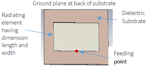
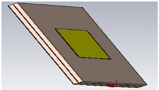
A simple rectangular patch antenna consists of four parts (Motin, Hasan, Habib, & Sheikh, 2013; Shimu & Ahmed, 2016); a rectangle form patch element, having certain length and width dimensions, used to radiating the fed signals, dielectric substrate having a certain relative permittivity (εr) and tangent loss (δ) value, a ground plane on back of substrate (not visible in figure 1) utilized to block radiations on back of substrate and a feeding point or a port to provide power from source to the radiating element. A simplified model is shown in Fig. 1.
Whenever a patch antenna needs to be designed, the first step is to find the dimensions for radiating the desired frequency. For rectangular patch it is required to find the width (W) and length (L) of the radiating element (Mikulasek & Lacik, 2011). These values depend on the substrate’s dielectric values (relative permittivity εr and tan loss value (δ)) and its height (h). The detail to calculate the required dimension for the resonance frequency (f0) are given as follows.
The width of a patch antenna, W, can be easily determined by using (Sidhu & Sivia, 2016)
Then next step is to calculate the overall length of the patch L. It can be determined using following equation.
Where (L represents the length that is extend due to the edge radiation effect, and Leƒƒ effective length that can be determined using following equation.
The effective dielectric constant (εreƒƒ), can be evaluated as follows. (Sidhu & Sivia, 2016)
And (L extended length caused by edge radition can be determented using following euation:
Using the above mentioned analytical equations, for the investigating frequency point i.e. 8 GHz the dimension of the raditing patch element for the considered substrate (detailed mentioned in table) were calculated and are given in Table 1.
Table 1 The detail of considered substrate and the calculated dimensions of the patch antenna at 8 GHz frequency.
| Resonate frequency | 8 GHz |
| Substrate material | Roger |
| εr | 2.2 |
| Substrate height | 1 mm |
| Loss tangent | 0.0009 |
| Width of the patch | 14.8mm |
| Length of the patch | 12.1 mm |
Then the electrical model was developed and its 3D numerical EM calculations were calculated and results will be presented in next section.
At the edge, the input is not 50 ohm therefore that need to matched, so that with high efficiency or with minimum reflections, the applied source could be matched with the connected load impedance. To performance this task various feeding were developed and are being utilized. But the problem by attaching these feeding techniques is that these them self-radiate or couple the EM signals which interact the radiating patch element radiation hence the output of antenna is modified and the designed radiating elements are changed. Which needed to determine the specific performance characteristic of the designed antenna system.
For excitation, the patch antenna is designed to operate at a resonance frequency of 8GHz. For this purpose, the length of the patch is taken as 12.1 mm on x axis. The width of its patch is taken as 14.8 mm on Y-axis. The height of the dielectric substrate for patch is taken as 1 mm on Z-axis and the value of dielectric constant (εr) is 2.2. The excitation patch of antenna is feed by either a probe feed or an edge feed. If the patch is table 4 being excited by feed, the distribution of charges is developed among the bottom of the patch & the ground plane as positively charged and the negatively charged. In this Research work, the edge feed is used to investigate the effect of excitation on the resonant behavior of different feeding techniques on the micro strip patch antenna so that it becomes polarized and the E-plane along the field direction & the H-plane would be perpendicular (Patel & Upadhyaya, 2019). It was found that the highest impedance was at the edge of the antenna and the maximum radiation resonates with the proximity feed coupled antenna as compared to the other feeding techniques.
Table 2 Specification of Coaxial feed.
| Name | Specification |
|---|---|
| Frequency | 8 GHz |
| Patch width W | 14.08 mm |
| Patch length L | 12.1 mm |
| Substrate thickness h1 | 1mm |
| Inner conductor ri | 0.1mm |
| Outer conductor r0 | 0.23mm |
Table 3 Specification of the microstrip patch antenna.
| Name | Specification |
|---|---|
| Frequency | 8 GHz |
| Patch width W | 14.08 mm |
| Patch length L | 12.1 mm |
| Width of the transmission line Wƒ | 0.83 mm |
| Length of the transmission line Lƒ | 4.9 mm |
| Width of antenna W0 | 3.1mm |
| Length of antenna L0 | 5.47mm |
Table 4 Specification of Aperture feed antenna.
| Name | Specification |
|---|---|
| Frequency | 8 GHz |
| Patch width W | 14.08 mm |
| Patch length L | 12.1 mm |
| Substrate thickness h1 | 1 mm |
| Substrate thickness h2 | 1 mm |
| The width of stripline Wƒ | 1.5 mm |
| The length of the feed line Lƒ | 18 mm |
| The width of aperture FW | 1.05 mm |
| The length of aperture F1 | 6mm |
| Stub length Lstub | 2.5mm |
2.1. Coaxial probe feed
The schematic of the coaxial feed technique for the patch antenna is shown in Fig. 2. In this method, the coaxial feed line of a desired values (mostly a 50 Ohm coaxial connector) is directly attached with the patch element at a point where its input impedance is matched with the applied source output impedance.
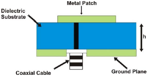
How away from the edge the point need to connected in patch can be calculated by following equation;
At the considered frequency, the dimension for the 50 ohm connector are Inner conductor, ri equals to 0.1 mm and out conductor, r0, equals to 0.23mm. It is connected 5mm away from the edge as shown in Fig. 2. The specification of Coaxial feed and microstrip patch antenna is given in Table 2 and 3.
2.2. Microstrip feed line
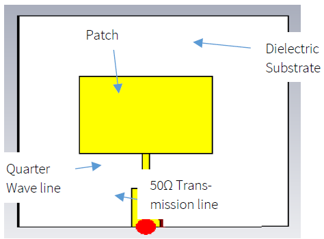
In this technique, impedance of the patch is matched using the microstrip feed line as shown in Fig 3. This line is used to transform the edge impedance to a value that is matched with applied source impedance value. The length of the attached line is quarter wavelength and have the transformed impedance value given as follows-
Where Z0 is source impedance, Zant is impedance of the patch element and ZT is impedance of transformed impedance microstrip line (Basilio et al., 2001, Inclán-Sánchez, Vázquez-Roy, & Rajo-Iglesias, 2009).
2.3. Aperture couple feed
To avoid the impact of EM fields radiated from the microstrip line with patch this technique is applied. In this technique the feeding line is attached on the back of ground plane separated using a substrate and a slot is created in the ground plane to couple the signal from feeding line to the patch (Civerolo & Arakaki, 2011). The length and width of slot impact the loading with the patch (Yon, Awang, Ali, Subahir, & Kamaruddin, 2016).
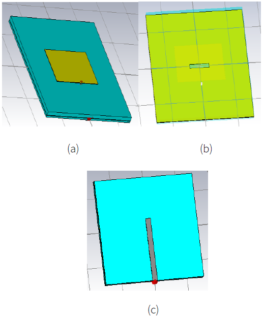
Design and modeling of aperture couple feed: The aperture coupled rectangular antenna consists of two dielectric substrates (Errifi, Baghdad, Badri, & Sahel, 2015), both are made up of Roger material having dielectric constant εr = 2.2 mm with (30×30×1) mm3 dimensions. These 2 dielectric substrates of the same thickness are separated by ground plane made of the copper thickness of 0.1 mm. A microstrip feed line of length Lƒ = 18mm and width Wƒ = 1.5mm is mounted on a lower substrate (Darimireddy, Reddy, & Prasad, 2015; Gummalla, Stoytchev, Achour, & Poilasne, 2010). A rectangular aperture of a length F1 = 6mm and width FW = 1.05 mm and stub length Lstu = 2.5 mm. Fig. 4 shows the top view, bottom view, and slot or an aperture, and the specification of Aperture feed antenna is given in Table 4.
2.4. Proximity couple feed
Design and modeling of proximity couple feed: Fig. 5 shows the structure of proximity coupled patch antenna, where the 2 dielectric substrates of the same thickness 1 mm and same dielectric constant εr = 2.2 mm are separated through the microstrip feed line. The length of the feed line is Lƒ = 15.6 mm, the width of stripline Wƒ = 2.8 mm. The feedline is centered with respect to radiating patch. The specification of proximity couple feed antenna is given Table 5.
3. Results and discussion
As already mentioned in section 1, when different feeding techniques are applied at the X band spectrum to improve the impedance matching of a radiating patch element, the performance of various characteristics parameters such as radiation pattern, gain, and beam width are influenced of the designed patch radiating antenna element due to the undesired EM radiations produces by these feeding line them self. To find this, a comparative analysis is carried out and results are presented in this section. First the results of a signal patch are presented then the results of impedance matching with various feeding is discussed and finally the comparison will be presented.
3.1. The patch radiating element
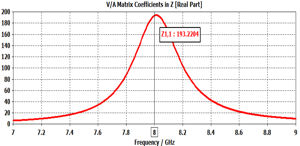
The impedance of the patch antenna describes the frequency is resonant at 8 GHz with the impedance of 193.2 Ohms shown in Fig. 5. For better performance, it is necessary to properly match the impedance at 50 ohm using various feeding techniques (Pan & Zheng, 2017).
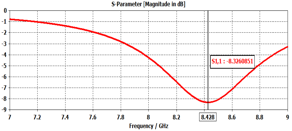
S-parameter of the patch antenna: Fig. 6, S-parameter calculation has been performed for radiating the patch antenna. The return loss for the patch antenna is -8.32 dB at frequency 8.42 GHz. The value of the reflection coefficient is more than -10 dB; which, indicates that power is rejected back toward the antenna. To overcome these reflections using feeding techniques that appropriately match with the patch.
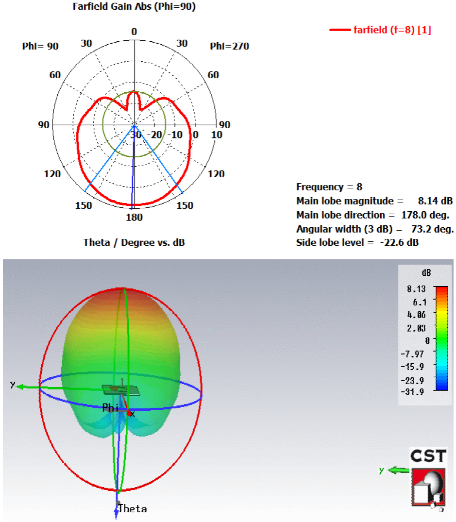
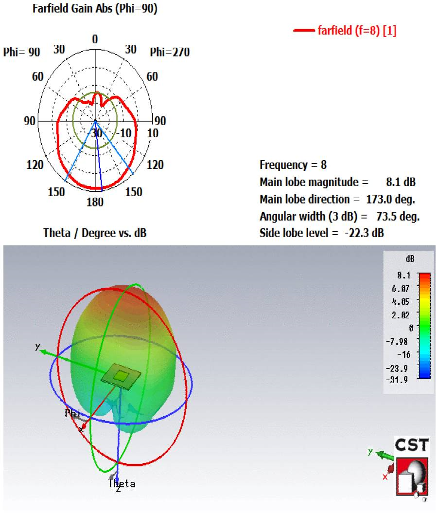
The gain of the patch antenna: The 3D and polar plot of the patch antenna is shown in Fig. 7. The simulated gain of a patch antenna according is 8.13 dB at 8 GHz frequency. The polar plot shows that the simulated antenna radiates maximum power towards the main lobe. Through the polar plot, the main lobe direction at the value of 178.00 and the angular width is 73.20 degrees is shown in the polar plot.
VSWR of the patch antenna: VSWR is an indication of the actual voltages that occur in a transmission line system when radio waves are being reflected. Fig. 8 shows the VSWR path against the frequency which graphically describes how the antenna matches when it is connected to the transmission line. The value of VSWR is 2.24 at the desired frequency.
3.2. Performance evaluation of the various feeding techniques:
The simulation of all four feeding techniques is performed using CST studio and the results of each feeding technique are described.
Simulation results of microstrip feed: The microstrip feed is the technique for matching characteristics impedance at 50 Ohms. The feed is directly connected to patch.
The impedance of Microstrip feed: Fig. 9 shows the impedance is approximately 52.2 Ω and resonates at 8.316 GHz frequency; the patch is matched with microstrip feed. The results of the patch antenna are summarized in Table 6. And VSWR is shown in Fig. 10.
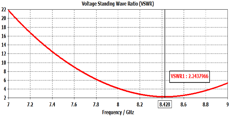
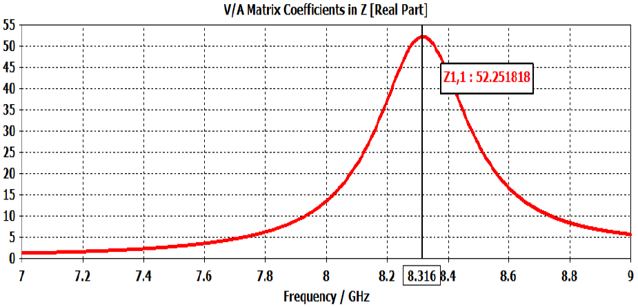
Table 6 Results for the patch antenna.
| Result | Impedance Ω | Gain dB | Main lobe Degree | Return los dB | VSWR |
|---|---|---|---|---|---|
| Single patch element | 193.2 | 8.1 | 179 | -8.32 | 2.2 |
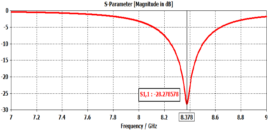
S-parameter of Microstrip feed: Fig. 11 shows S-parameter calculation has been performed for the radiating patch antenna. The return loss for Strip-line patch antenna is (S11 = -28.2 dB) at frequency 8.37 GHz which is less than -10dB. The value of the reflection coefficient indicates that impedance appropriately matches and maximum power transfer to the load.
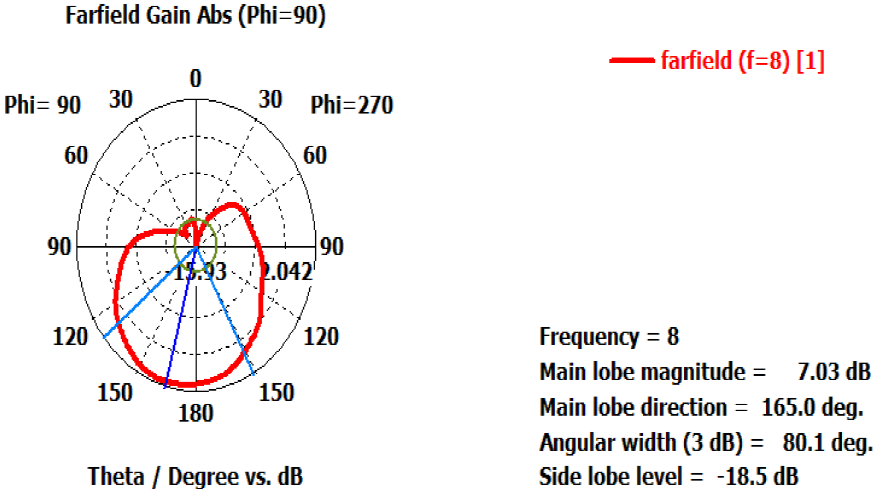
The gain of Microstrip feed: 3D and polar plot of microstrip feed are shown in Fig. 12. The gain represents how well the antenna radiated power in a specific direction and the simulated gain is 7.03 dB, the simulated antenna radiates maximum toward the main lobe. Therefore, the main lobe focused at the angle of 165.00 and an angular width of 80.10.
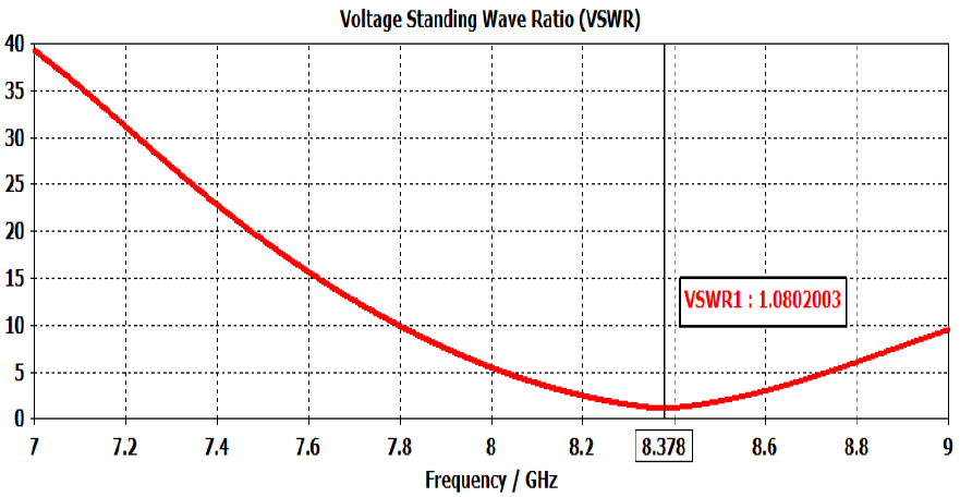
VSWR of Microstrip feed: Fig. 13 shows the VSWR path against the frequency which graphically describes how the antenna matches when it is connected to the transmission line. The value of VSWR is 1.08 at the desired frequency and the standard value is ≤ 2. The value obtained from VSWR is low and it shows a better result.
Comparison of the patch vs Microstrip feed: The comparative results for the patch antenna with the microstrip feeding technique are shown in Table 7.
3.3. Simulation results of coaxial probe feed
The coaxial probe feed is very rarer in a patch antenna because the feed can be located anywhere in the top of the patch antenna. The proposed antenna is fabricated on Roger substrate having thickness 1 mm and the value of the dielectric constant is 2.2, and loss tangent of 0.009. The simulation result of the coaxial probe feed is discussed below.
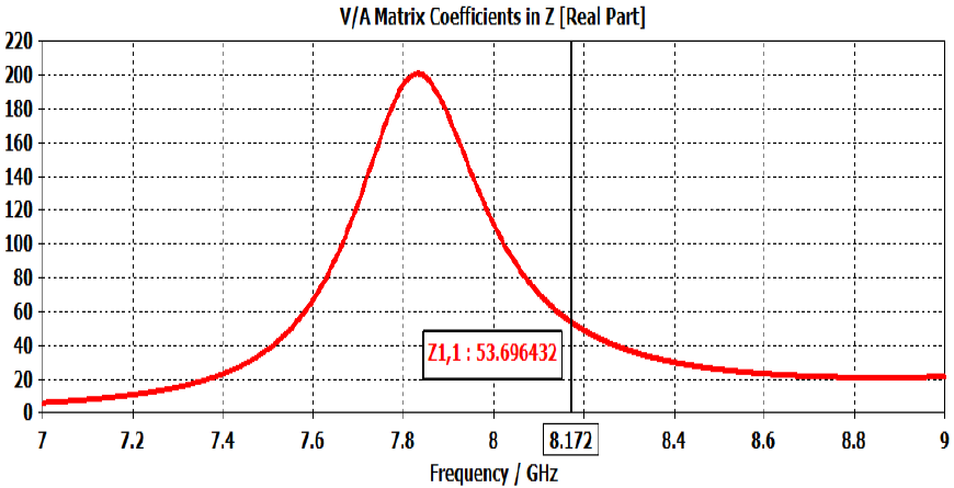
The impedance of coaxial feed: Fig. 14 shows the impedance of the coaxial probe feed. The impedance of coaxial feed is 53.6 ohm at 8.172 GHz frequency. As the dimensions of the inner conductor, the outer conductor is too small at a higher frequency, the peak value is not at a specific frequency and its move towards the right.
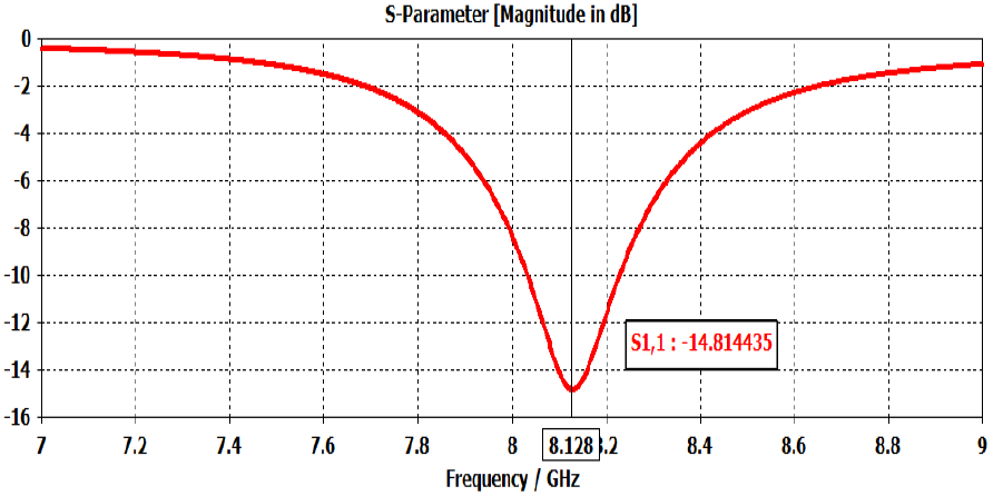
S-parameter of coaxial probe feed: S-parameter calculation has been performed for the coaxial patch antenna. Fig. 15 shows that the return loss for a coaxial patch antenna is (S11 = -14.8 dB) at frequency 8.12 GHz which is less than -10 dB. It can be analyzed from the graph that return loss of coaxial probe feed has no considerable impact on antenna performance.
The gain of coaxial probe feed: The simulated gain of the coaxial antenna according to Fig. 5 is 8.1 dB, Fig. 15 shows the 3D and polar plot of coaxial feed. The simulated antenna radiates maximum toward the main lobe. The main lobe focused at the angle of 17.00 and an angular width of 73.50.
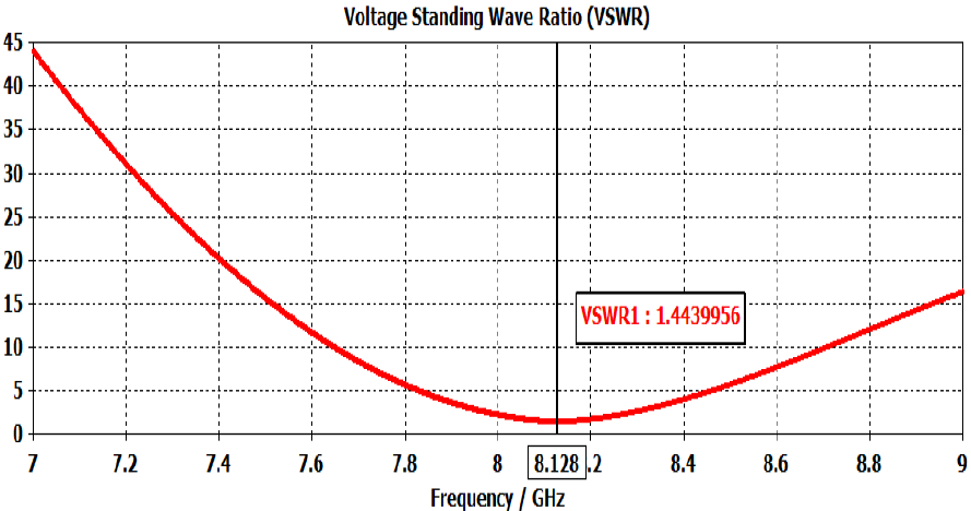
VSWR of coaxial probe feed: Fig. 16 shows the VSWR path against the frequency which graphically describes how the antenna matches when it is connected to the transmission line. The value of VSWR is 1.44 at the desired frequency and the standard value is ≤2.
Comparison of the patch vs Coaxial feed: The comparative results for the patch antenna with coaxial feed are shown in Table 8.
3.4. Simulation results of aperture couple feed
This type of feeding technique is also used to match the antenna with the transmission line at 50 Ohms characteristics impedance. The simulation results discuss how much impact on antenna performance.
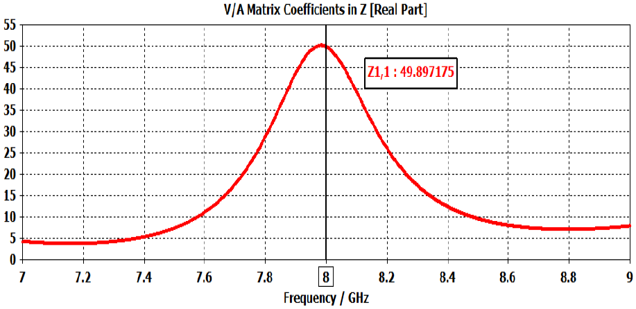
The impedance of the Aperture couple feed: Fig. 17 shows the impedance of aperture couple feed which describes the frequency is resonant at 8 GHz with characteristics impedance of 49.89 Ohms. The radiating patch is properly matched with the transmission line.
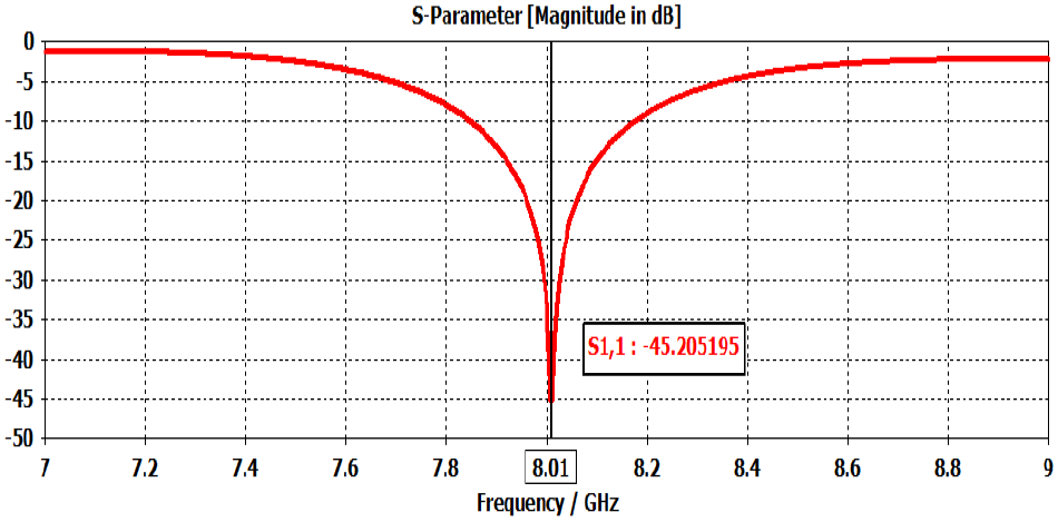
S-parameter of aperture couple feed: S-parameter calculation has been performed for aperture couple feed antenna. The return loss for aperture couple feed antenna is (S11 = - 45.2 dB) at frequency 8.01 GHz. Fig. 18 shows more negative return loss, the gain antenna in a particular direction. The aperture couple feed antenna has more negative return loss so it has less impact on the antenna performance than the other two feeding techniques.
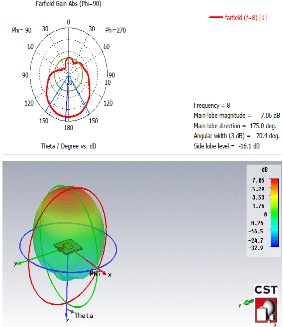
The gain of aperture couple feed: The 3D and polar plot of aperture coupled feed are shown in Fig. 19. The gain represents how well the antenna radiated power in a specific direction and the simulated gain is 7.06 dB. The simulated antenna radiates maximum toward the main lobe. The main lobe focused at the angle of 175.00 and an angular width of 70.40.
VSWR of aperture couple feed: Fig. 20, the VSWR path against the frequency which graphically describes how the antenna matches when it is connected to the transmission line. The value of VSWR is 1.03 at the desired frequency and it ≤ 2.
Comparison of the patch vs aperture feed: The comparative results for the patch antenna with an aperture feed technique is shown in Table 9.
3.5. Simulation results of proximity couple feed
Proximity coupled antennas have a number of advantages like wider bandwidth with dual-band operation, low surface wave losses, low losses from the feed-in comparison with coaxial feeding and produces linear and circular polarization. By varying the width of Strip-line, the height of different substrate and stub length different results conclude.
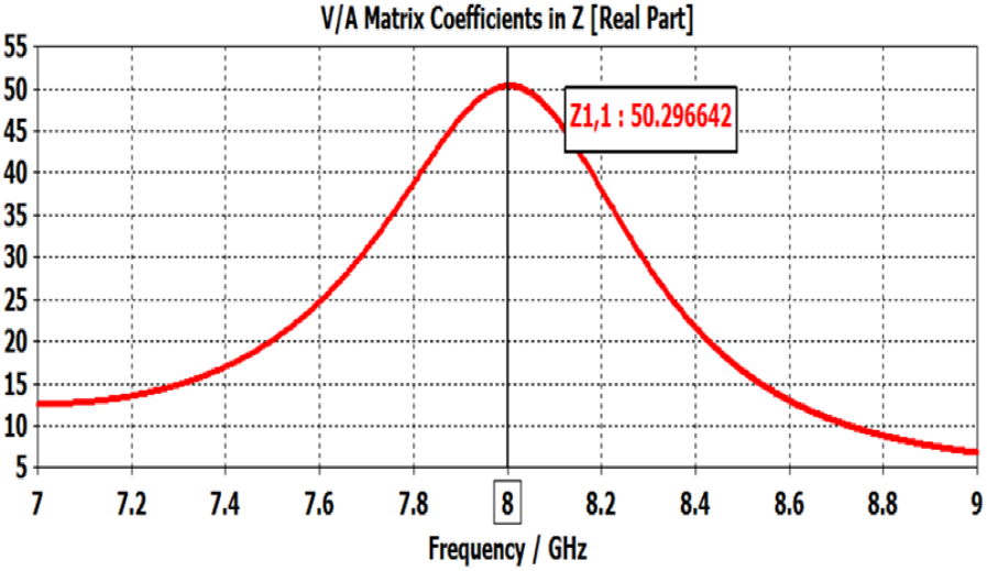
The impedance of Proximity couple feed: The impedance of proximity couple feed which describes the frequency is resonant at 8 GHz with characteristics impedance of 50.2 Ohms, Fig. 21, and the patch is properly matched with the transmission line.
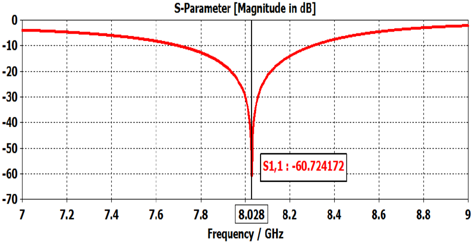
S-parameter of proximity couple feed: S-parameter calculation has been performed for proximity couple feed antenna. The return loss for aperture couple feed antenna is (S11 = -60.7 dB) at frequency 8GHz.
Fig. 22 shows the impedance of proximity couple feed which is higher at frequency of 8GHz. Further, Fig. 23 shows more negative return loss, the gain antenna in a particular direction. The proximity couple feed antenna has more negative return loss so it has less impact on the antenna performance than the other three feeding techniques.
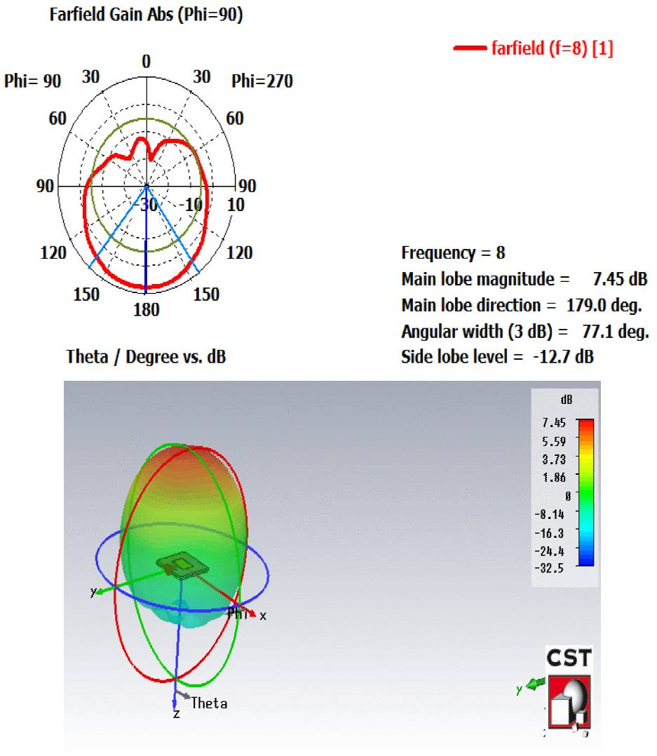
The gain of proximity couple feed: Fig. 24, the proximity couple feed has a maximum gain of 7.45 dB at a frequency of 8.01 GHz. The simulated antenna radiates maximum toward the main lobe. The main lobe directed at the angle of 179.00 and an angular width of 78.50.
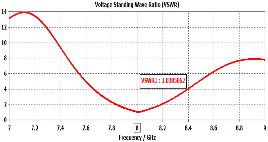
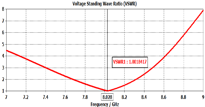
VSWR of proximity couple feed: Fig. 25 shows the VSWR path against the frequency which graphically describes how the antenna matches when it is connected to the transmission line. The value of VSWR is 1.001 at the desired frequency and its standard value is less than 2.
Comparison of the patch antenna vs proximity feed: The comparative results for the patch antenna with the proximity feed technique is shown in Table 10.
Table 10 Comparison of the patch antenna vs proximity feed.
| All feeding techniques | Impedance Ω | Gain dB | Main lobe Degree | Return los dB | VSWR |
|---|---|---|---|---|---|
| Single Patch Element | 193.2 | 8.1 | 179 | -8.32 | 2.2 |
| Proximity | 50 | 7.45 | 179 | -60.7 | 1.00 |
A comparative analysis is made between all four feeding techniques in terms of gain, impedance, return loss and VSWR of patch antenna with various feeding techniques are presented in Table 11.
4. Conclusions
In this paper, the comparison of different feeding techniques for the patch antenna, at X frequency band, to evaluate its quantitative impact on the different antenna parameters is presented. The single radiating patch antenna has a high gain of 8.13 dB at 8 GHz frequency and radiated maximum power in the main lobe direction which is 178.0 degrees. From the comparative analysis, it is found that the impact on the radiation gain of a single patch antenna is less when the system is fed using proximity couple feed as compared to microstrip, coaxial and aperture. The coaxial probe feed has higher gain 8.1 dB and no effect on gain radiation but return loss (S11 = -14.8 dB) are less compared to other feeding techniques. A proximity couple patch antenna and an aperture coupled patch antenna has more negative return loss (S11 = -60.7 dB) and (S11 = -45.2 dB) and provide better impedance matching as compared to the coaxial and microstrip technique. The proximity couple patch antenna has a minimum impact of various parameters at the X-band compared to the other feeding techniques.
Future work: Find out some analytical ways on how to design the feeding technique especially (aperture couple and proximity couple).

