


 text new page (beta)
 English (pdf)
 Article in xml format
 Article references
 Send this article by e-mail
 Cited by SciELO
  Similars in
SciELO
Similars in
SciELO 
 Permalink
1. Introduction
Roads are one of the most valuable assets of any country, and its maintenance and rehabilitation prevent road traffic accidents and reduces their consequences (AdrianaTisca, Istrat, Dumitrescu, & Cornu, 2016; Bardal & Jørgensen, 2017; Celauro, Corriere, Guerrieri, Lo Casto, & Rizzo, 2017). Ideally, the maintenance of roads should be accomplished with minimum expense and with the least possible disruption of traffic in order to lessen the possibility of vehicular accidents (Yarmukhamedov, Smith, & Thiebaud, 2020). The use of automated equipment is one of the modern means to improve the quality in road constructions and maintenance reducing in most cases the time and cost of this process (Mikolaj & Remek, 2016). Not only the quality of the road is a critical aspect to consider, but also the safety of human operators whose work is to repair the road work zones. Highway work zones present one of the most hazardous of all roadway environments (Whitmire, Morgan, Oron-Gilad, & Hancock, 2011). The risk is not only for the drivers who transit on these work zones but also the workers who perform the road reparation.
When a road is in its maintenance phase, passive or active signaling systems are used to warn the driver. Passive signals provide only a stationary sign regardless of approaching vehicles to the repairing section. Therefore, the message remains constant with time. Active systems are automatic warning devices, such as flashing arrow panels, robotic flagmen, among others, which prevents the driver that a section of road is being repaired. Even when the use of automated equipment will increase the safety of human operators, relatively little research has been conducted in this area.
Tey, Ferreira, and Wallace (2011) evaluate passive and active warning devices in relation to driver behavior considering railway level crossing situations. Their study showed that in most cases the driver simply fails to see passive warnings compared to active ones. Also, they indicate that human factors like distraction and fatigue are frequent reasons affecting driver behaviors. For example, they found that the majority of drivers who violated warning systems were regular users of the level crossing. The authors concluded that on average, driver responses to passive signs are poor compared to active ones.
Different researchers have developed advanced assistance systems to alert the driver of a potential collision (Biondi, Strayer, Rossi, Gastaldi, & Mulatti, 2017; Lylykangas, Surakka, Salminen, Farooq, & Raisamo, 2016; Navarro et al., 2017). Schwarz and Fastenmeier (2017)) conducted a driving simulator study with 88 participants. They use augmented reality as an advanced technology to display auditory and visual warning information in the vehicle. In their research, they mentioned the phenomenon that with the introduction of additional warnings in vehicles may unintentionally increase the frequency of false alarms. False alarms lower drivers’ trust in an alert vehicle system. Therefore, in some cases, the driver will ignore or turn off the vehicle warnings after several false alarms. Schwarz and Fastenmeier reported in their results potential benefits of augmented reality coding to improve future collisions warnings. Whitmire et al. (2011) investigated the effectiveness of in-vehicle information technologies (audio and visual warning systems) to influence driver speed in work zones. Their research was conducted in a driving simulator that produced three different warnings: a) the driver was approaching a work zone; b) the driver had entered a work zone; and c) the driver has exceeded the posted speed limit. The visual warnings were presented on an HP IPaq pocket PC mounted on the vehicle’s dashboard. The audible warnings were delivered via a small speaker set installed beneath the visual display device. Rylander and Axelsson (2012) reported how wireless communications and Vehicular Ad Hoc Networks (VANET) technologies can be used in relation to road work zones to increase safety. The main concept in VANET is the periodically broadcast of speed, position, and direction between vehicles within a particular range. This information is commonly used to optimize traffic flow, decrease fuel consumption and prevent accidents. Even when the simulation results of these previous studies were very promising, the vehicle needs the incorporation of new technology. Also, complex communication and control systems must be implemented. This may not be a feasible solution for some population sectors due to the cost of its implementation.
Bai, Yang, and Li (2015) pointed out that statistics of work zones crash rates have shown a severe traffic safety problem. Truck-related work zone crashes are more severe than other crashes in work zones. Some of the reasons for these accidents include the number of traffic lanes, light conditions, and driver errors such as misjudgment/disregarding traffic control signs and signals. The authors studied the effective location of a portable changeable message sign (PCMS) in work zones. The messages displayed on the PCMS were: “WORK ZONE/ AHEAD/ SLOW DOWN” and “FLAGGER/ AHEAD PREPARE /TO STOP”, changing every three seconds. They monitored the changes in speed profiles in trucks and passenger cars. Reducing the speed variability between trucks and passengers cars might potentially mitigate the risk of crashes in work zones. This research demonstrates the importance to determine the effective location of active warning devices that can be used to reduce crashes in road work zones.
Another strategy commonly used to alert the driver of its approximation to a road working zone is by the use of flagmen. The U.S. Patent No. 6,104,313 (2000) presets an automated, portable traffic control device designed to replace a human flagman. The user controls the display of a STOP and SLOW signs by a remote control unit. These signs are placed in a tripod support system, therefore, the traffic control device does not have a human silhouette. This device can be used with an automotive battery and should provide twelve hours of operation on one charge. Another solution is presented in the U.S. Patent No. 6,052,067 (2000). A simulated flagman with a head, a torso, and an arm is attached to a traffic control device. A two-sided traffic control sign (STOP/SLOW) is supported on an arm of the robotic flagman and a motor turns the sign 180 degrees in either direction to expose the traffic control signs. This device could be controlled by a human operator or by a timer and monitored with a camera. The recommended power supply is a 6-volt sealed battery, but it is not indicated its durability under continuous use. The U.S. Patent No. 2008/0204276A1 (2008) introduce an adjustable traffic control system having a STOP/SLOW sign and a movable arm. The system is powered by a 12-volt automotive charging system with the option to connect to a small solar panel to maintain the battery in top conditions. The operability of the flagmen is monitored by a remote video camera attached to each system. The South Korea Patent No. KR20160023136A (2016) presents a robot flagman invention whose left and/or right arm members are rotated up and down to indicate lane changes. The patent description is mainly focused on the mechanical design of the robotic flagmen. The electronic components of the device are not specified.
In Mexico is very common to see a human worker waving a flag in road work zones. Therefore, the use of a robotic flagman will reduce the risk of human injuries. This paper describes the implementation of two robotic flagmen controlled and monitored by the Controller Area Network, CAN, 2.0B. Right/Left speed reduction and lane change functions are programmed in each robotic flagman. Each robot has the option to be powered by solar panels considering working zones where there is no access to the electric grid. The novelty of this proposal consists of two main points: a) the control and monitoring of these robotic flagmen by the CAN protocol, and b) the solar charging system that assures a complete operability of the flagman at night conditions. The hardware combination in the control, monitoring, and solar charging system allow us to propose a low-cost practical implementation. There is no need to include extra hardware in the setup such as a video camera or complex communication and control systems in the vehicle. The same CAN circuitry used to control the robotic flagmen is used for its monitoring. In most patent designs the robot needs to be energized by a high power automotive battery system that needs a high rating current charging. Our proposal uses a low power battery which cost is lower compared to an automotive. Also, the dimensionality of our solar charging system (solar panels, sealed lead-acid battery, and its charger) is significantly reduced because the battery rating current charging is low.
The rest of this paper is organized as follows. Section 2 describes how the robotic flagmen are programmed and controlled. Section 3 presents the experimental results and Section 4 concludes the paper.
2. Robotic Flagman description
According to the Mexican National Development Plan 2019-2024, (DOF - Diario Oficial de la Federación, n.d.) the country’s road network consists of 407.958 km. Of these, 40,583 km make up the toll-free federal network. By the end of 2018, only 25% of the toll-free federal road network was in good conditions, 40% was in regular conditions, and 35% was in bad conditions(http://dof.gob.mx/nota_detalle.php?codigo=5596042&fecha=02/07/2020). A strategic plan for Mexico should be to maintain, expand and modernize this road network. By doing this, the Mexican economy will improve its international competitiveness and its internal markets. An important aspect to consider in the maintenance end expansion of roads is the safety of the human workers. Our work is in this same sense. In order to increase the security of workers, we developed two robotic flagmen controlled and monitored by the CAN bus protocol. In Mexico, it is very common to find human flagmen indicating that a portion of the road is being repaired. By using robotic flagmen, the security of the human person will be in increased. In this part of the document will be described the implementation details of these robotic flagmen, how the CAN bus protocol is implemented and the necessary hardware used in our robots.
2.1. CAN Bus Protocol
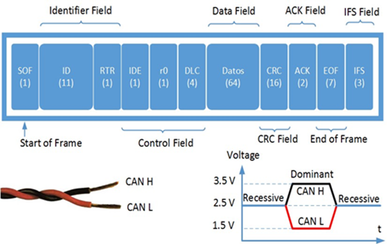
The Controller Area Network, CAN, is a serial communication bus, developed by the Bosch company for the automotive industry in 1985 (Natale, 2008). Due to its robustness to high immunity to electrical interface and its ability to self-diagnose and repair data errors, the CAN bus is also used in the building automation, medical, robotics, and manufacturing (Corrigan, 2002). The CAN bus protocol uses asynchronous communication, and the transmission rate depends on the bus length and transceiver speed. All contending messages in the CAN protocol have a unique identifier. CAN specifies two voltage states: recessive and dominant. A dominant state occurs when the differential voltage between the CANH and CANL pins of the CAN transceiver is greater than a specified voltage (e.g., 1.2 V). A recessive state occurs when the differential voltage is less than a defined value (typically 0 V). The CAN 2.0B defines two formats for communication: a) Standard data frame that uses 11 identifier bits, and b) extended data frame that uses 29 identifier bits. This paper uses the standard data frame because our solution only considers 5 different identifiers to control and monitor the two robotic flagmen. The standard data frame could meet these requirements. The start of a frame transmission is denoted by the start of frame (SOF) bit (used to synchronize the nodes on the bus) followed by the identifier (ID) field. The lower the binary value of the identifier, the higher its priority. The remote transmission request (RTR) bit recognize remote request frames (recessive) or data frames (dominant). The ID and RTR bits form the Identifier Field. The Control Field is composed of the identifier extension bit (IDE), a reserved bit (r0), and four bits of the data length content (DLC). For the standard data frame, the IDE and r0 bits must be dominant. The DLC bits are the unsigned binary coding of the length of the data content. The data to be transmitted is sent to the Data Field (up to 64 bits). The CRC Field (cyclic redundant check) is composed of 15 bits plus a delimiter bit. This field contains the checksum of the proceeding application data for error detection. The Acknowledge Field (ACK) consists of two bits. The CAN protocol requires that receivers acknowledge reception of the message change the content of the ACK field. The End of Frame Field (EOF) indicates the end of the message, and it is composed of 7 bits. For Standard Data Frames the seven bits must be recessive. The Inter-frame Space (of at least three bits) is used to separates messages in the CAN protocol. Figure 1 shows a diagram of the CAN Standard data frame, an example of the twisted wires of the CANH and CANL pins of the CAN transceiver, and the voltages of the dominant and recessive states.
2.2. Control of the Robotic Flagmen, RAF1 and RAF2
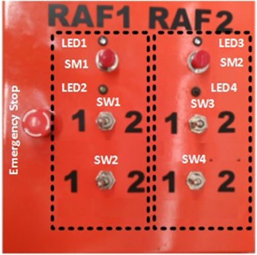
The two Robotic Flagmen, named RAF1 and RAF2, are controlled by a Master Node case (MNc). The MNc has a total of four switches, two for each robot. The position of these switches (SW) defines the action to be performed by the robot. The actions programmed for RAF1 are: speed reduction left lane (A1), left lane change (B1), speed reduction right lane (C1), and right lane change (D1). A1 is programmed when SW1 and SW2 are in position 1. B1 is programmed when SW1 is in position 2 and SW2 in position 1. C1 is defined when SW1 is in position 1 and SW2 in 2. The action of D1 is programmed when SW1 and SW2 are in position 2. For the second robot, RAF2, there were used SW3 and SW4 with a similar switch configuration. Table 1 summarizes this description. The MNc has three push-buttons that will stay in their “pressed” or “unpressed” position with every push of the button. One push-button is the emergency stop, and the other two buttons SM1 and SM2 will send the messages configured by the switches while they are in their “pressed” position. Four LEDs monitor the status of the messages. LED1 and LED3 indicate that the message programmed by the switches have been sent. LED2 and LED4 show that the robots are performing the configured actions. Figure 2 shows the Master Node case.
Table 1 Switch configuration of the two Robotic Flagmen.
| Robot RAF1 | ||
| SW1 | SW2 | Action |
| 1 | 1 | Speed reduction left lane (A1) |
| 2 | 1 | Left lane change (B1) |
| 1 | 2 | Speed reduction right lane (C1) |
| 2 | 2 | Right lane change (D1) |
| Robot RAF2 | ||
| SW3 | S42 | Action |
| 1 | 1 | Speed reduction left lane (A2) |
| 2 | 1 | Left lane change (B2) |
| 1 | 2 | Speed reduction right lane (C2) |
| 2 | 2 | Right lane change (D2) |
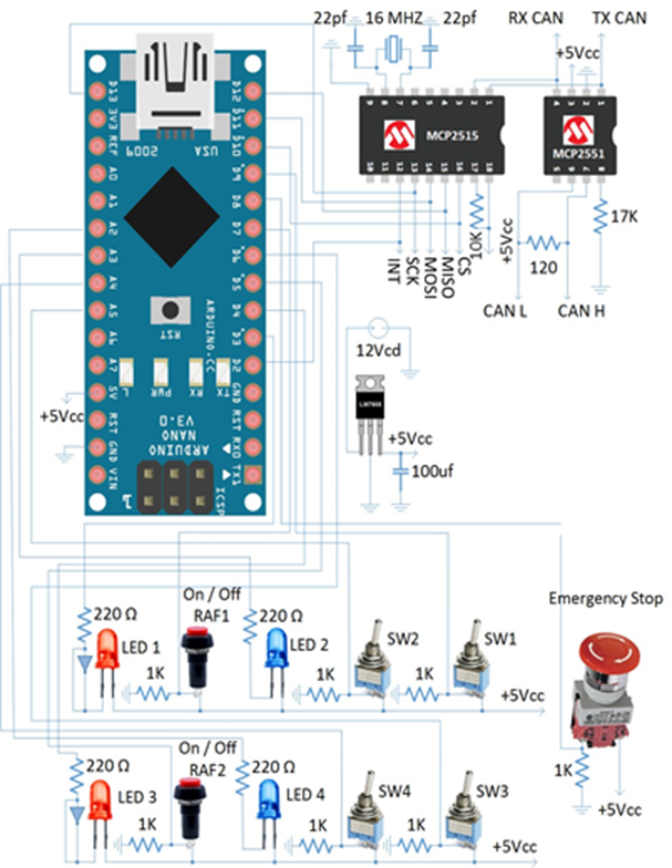
The circuitry implemented in the MNc is presented in Figure 3. The electronics are based on the microcontroller ATMEGA328P embedded in the Arduino Nano card. The ATMEGA328P is responsible for managing the reading/writing CAN messages. The MCP2515 standalone CAN controller with Serial Peripheral Interface (SPI) implements the CAN specification version 2.0B. The MCP2515 communicates with the ATMEGA328P via SPI. The MCP2551 is a high-speed CAN transceiver that implements the physical bus of the CAN bus protocol.
2.3. Circuitry of RAF1 and RAF2
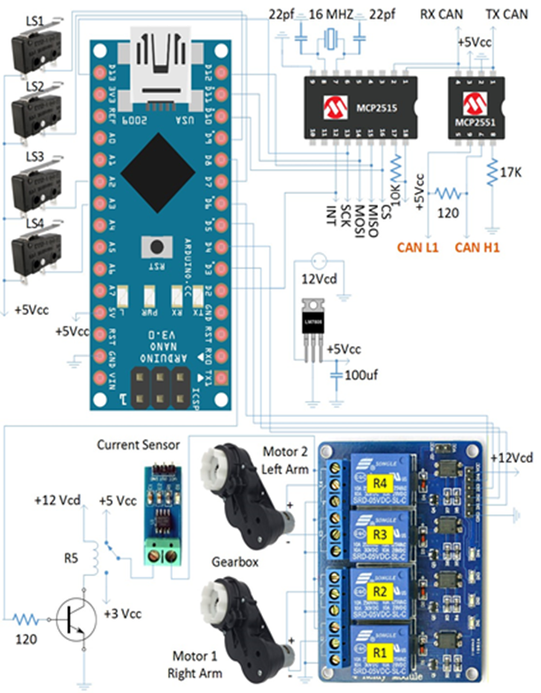
The electronics of each robot is explained next. Similar to the circuitry of the Master Node case (MNc), the ATMEGA328P, MCP2515 and MCP2551 are used to send and receive the CAN messages. Two direct current (DC) motors with a gearbox, high torque, and low speed, handle the movement of the robot’s arms. Movement and stopping of each arm are controlled by two relays (R). R1 and R2 control the DC motor of the right arm, R3 and R4 control the motor of the left arm. The function of the relay R5 is to lower the voltage of the DC motors to reduce the velocity of the arm when it is moving down. The current sensor ACS712 is implemented to measure the current that are consuming the DC motors. Therefore, according to this current measurement, we can have a feedback of the movement that is performing the robot. Four limit switches (LS) were included to limit the maximum and minimum angle of the arms position in the different actions that the robot can perform. RAF1 and RAF2 use the same electrical circuitry. Therefore, only one schematic is shown in Figure 4.
2.4. CAN database of the Robotic Flagmen
As previously mentioned, our implementation uses the standard data frame of the CAN 2.0B protocol. We defined five identifiers. The identifiers 11 and 12 are used to indicate the operations that are performing the RAF1 and RAF2 robots. Identifiers 13 and 14 were configured to measure the current consumption of the DC motors in RAF1 and RAF2 respectively. The identifier 15 indicates that the emergency stop has been pressed or released. Table 2 shows the complete CAN database implemented in our project.
Table 2 CAN database.
| Description | Id. | Data |
| Speed reduction left lane (A1) | 11 | 01 00 00 00 00 00 00 00 |
| Left lane change (B1) | 11 | 03 00 00 00 00 00 00 00 |
| Speed reduction right lane (C1) | 11 | 02 00 00 00 00 00 00 00 |
| Right lane change (D1) | 11 | 04 00 00 00 00 00 00 00 |
| RAF1 off | 11 | 00 00 00 00 00 00 00 00 |
| Speed reduction left lane (A2) | 12 | 00 01 00 00 00 00 00 00 |
| Left lane change (B2) | 12 | 00 03 00 00 00 00 00 00 |
| Speed reduction right lane (C2) | 12 | 00 02 00 00 00 00 00 00 |
| Right lane change (D2) | 12 | 00 04 00 00 00 00 00 00 |
| RAF2 off | 12 | 00 00 00 00 00 00 00 00 |
| Current measure of RAF1 | 13 | 00 00 xx 00 00 00 00 00 |
| Current measure of RAF2 | 14 | 00 00 xx 00 00 00 00 00 |
| Emergency stop ON | 15 | 00 00 00 01 00 00 00 00 |
| Emergency stop OFF | 15 | 00 00 00 00 00 00 00 00 |
2.5. Flow diagrams descriptions of the Master Node and Robotic Flagmen
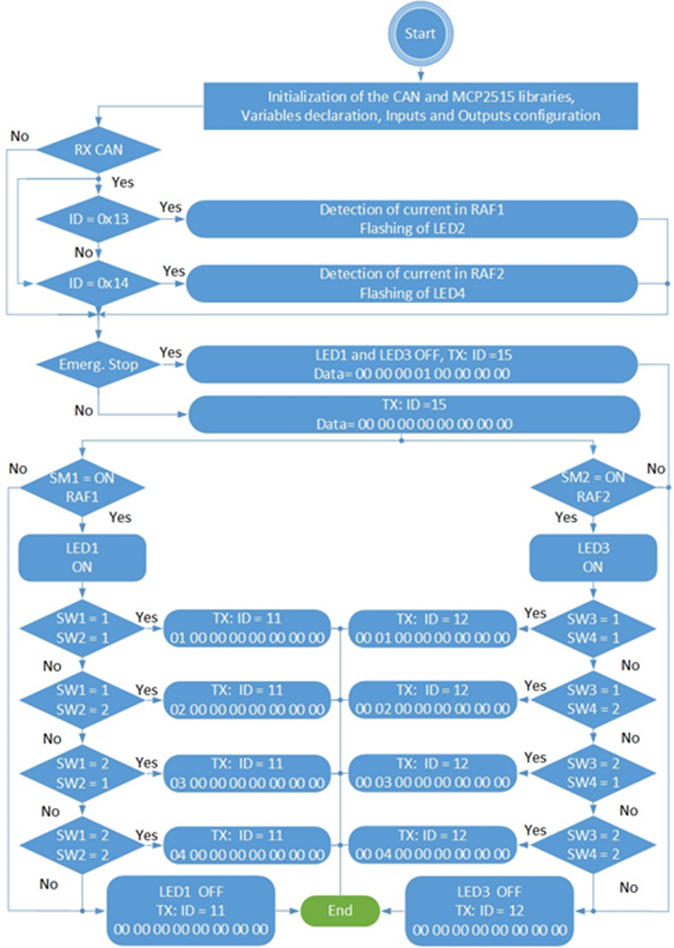
The flow diagram of the Master Node configuration is shown in Figure 5. The flow chart starts with the initialization of libraries for the MCP2515, the declaration of the necessary inputs to read the status of SW1, SW2, SW3, SW4, SM1, SM2 and the Emergency Stop. Also, the outputs associated with LED1, LED2, LED3, and LED4 are declared. Next, the CAN message related to the consumption of current in RAF1 and RAF2 are revised. The current consumption is an indicator that the robots are active. If this is the case, the LED2 and LED4 will be flashing. The next message to monitor is the Emergency Stop status. If the Emergency Stop is in the ON position, LED1 and LED3 will be OFF, and the CAN message with ID 15 will be 00 00 00 01 00 00 00 00. Contrary, if the Emergency Stop is OFF, the positions of the four switches SWn, and SM1 and SM2 buttons are monitored in order to send the corresponding CAN message to the robots RAF1 and/or RAF2.
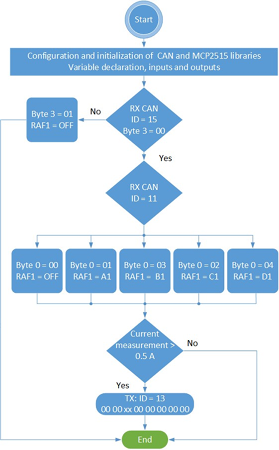
The flow diagram of the Robotic Flagmen configuration is shown in Figure 6. The first step is to initialize the libraries of the CAN and MCP2515 integrated circuits. Also, it is necessary to set the proper value to the variables associated with the limit switches, LSn, and the relays outputs, Rn. Once initialized all these variables and libraries, the program will check the CAN message with ID 15 in order to confirm that the Emergency stop is OFF. If this is the case, the program will be waiting for the CAN message with ID 11 to perform an action on RAF1. All the possible actions (A1, B1, C1, and D1) are programmed within the byte 0 of this CAN message. These robot movements will produce a consumption of current. The current measurement will be sent through the message ID 13 in the byte 2. The configuration of RAF2 is similar to RAF1 but with a different ID (12 instead of 11) and CAN messages as described previously in Table 2.
2.6. Components of the Robots RAF1 and RAF2
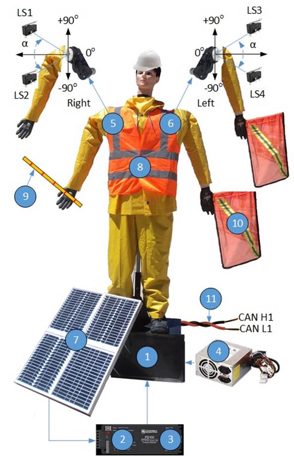
Figure 7 shows the components of the RAF robots. The base of the robots is made of steel (1). On this base is the electronic circuitry, a sealed lead-acid battery (2), a solar charger (3), and a power supply of 110 Vac (4). As previously mentioned, the robots have the capacity to operate in remote places where the power grid may not be available. Therefore, they can work with solar energy. Each arm of the robot is connected to a DC motor with their associated gearbox (5)-(6). Two LS’s limit the movement of each arm to specific angles referenced with the horizontal axis. Four solar panels (7) with a parallel connection and a maximum power of 10 W - 17.4 V are used to charge the battery by using the PS100 charger. The robots wear a yellow suit with reflective strips (8), they hold a rod to indicate a lane change (9) and a flag to indicate a speed reduction (10). The CAN twisted cables are in (11).
The arm location of the robots is configured with the positions of the switches of the Control Master case. This configuration is sent to the robots through the CAN messages. The DC motors, gearbox and limit switches control the final angular position referenced with the horizontal axis. Table 3 summarizes these angular positions.
Table 3 Angular position of the Robot’s arms.
| Description | Left Arm | Right Arm |
| Speed reduction left lane (A1) and (A2) | −90◦ → 0◦ →−90◦ Repetitive pattern | −90◦ |
| Left lane change (B1) and (B2) | 0◦ → +90◦ → 0◦ Repetitive pattern | 0◦ |
| Speed reduction right lane (C1) and (C2) | −90◦ | −90◦ → 0◦ →−90◦ Repetitive pattern |
| Right lane change (D1) (D2) | 0◦ | 0◦ → +90◦ → 0◦ Repetitive pattern |
3. Experimental Results
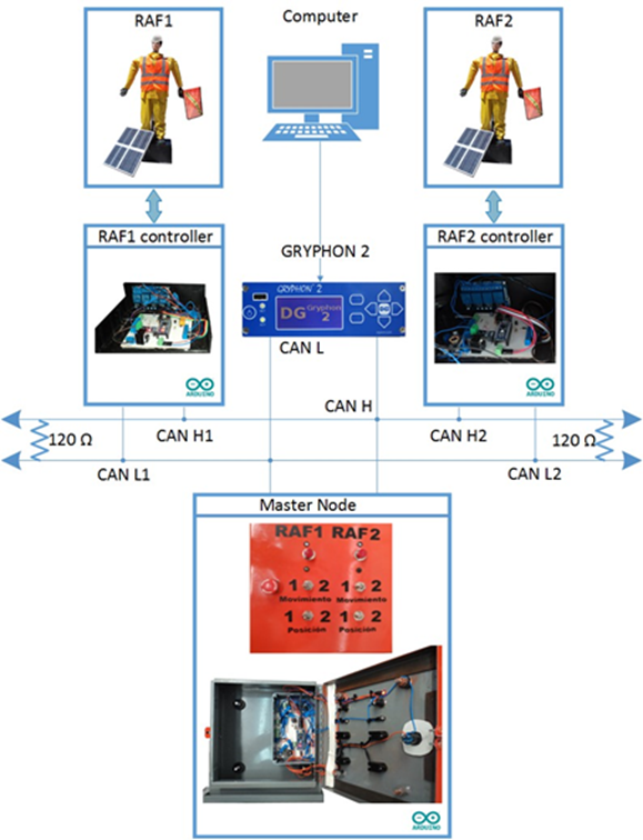
The hardware implementation of the Master Node and Robotic Flagmen are shown in Figure 8 (a) and (b) respectively. The GRYPHON G2 is a high-end tool for the analysis of messages on the CAN bus. The GRYPHON in conjunction with the Hercules V5.1 program monitors the CAN network.

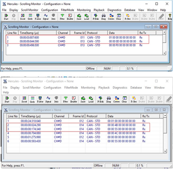
In our configured set up, the GRYPHON was placed 1 m away of the Master Node. The first robot, RAF1, was placed 2 m away of the Master Node and 20 m away from the second robot, RAF2. Figure 9 shows our setup used to validate the traffic of CAN messages. Figure 10 shows the traffic of messages in our network considering a speed of 10 Kbps in the CAN bus. The GRYPHON has the ability to transmit messages, not only to monitor. In the tests shown in the previous figure, the GRYPHON only monitors the CAN bus, for this reason, the message status in only RX (receive messages). The upper part of this figure shows the transmission of the messages A1 (ID 11). 844.59 ms latter the GRYPHON detects the respective measurement of current consumption in the message with ID 13. The lower part shows the transmission of the A2 message (ID 12). 24.290 ms later, there is detected the current consumption of this action in the CAN message with ID 14.
The power consumption of the robotic flagman was calculated based on its component specification datasheets and the nominal current measured in each motor. The total power consumption calculated on the circuitry of Figure 3 was 0.5 W approx. The circuitry shown in Figure 4 consumed 6.5 W. The battery specification indicates a capacity of 84 Wh (7Ah*12V). This means that our design can provide an autonomy of about 12 h (84Wh/ (0.5W+6.5 W)), sufficient for the robot to operate all night. The time it takes for the battery to be fully charged is 5.8 h approx. (84Wh/(1.2A*12V )) by considering a PS100 charger of 1.2 A and a battery of 7 Ah.
4. Conclusions
In this paper is presented the implementation of two Robotic Flagmen (RAF1 and RAF2) controlled by the CAN 2.0B bus.
Each robotic flagman can perform four different movements: Speed Reduction Left Lane, Left Lane Change, Speed Reduction Right Lane and Right Lane Change. These movements are controlled by the position of four switches placed in a Master Node case. The circuitry used to control the CAN bus are based on the ATMEGA328P, SPI MCP2515, and MCP2551 integrated circuits. The implementation of our proposal system doesn’t need to incorporate more expensive electronic devices such as cameras, or new technology in the vehicle which leads to complex communication and control systems. Also, as demonstrated in the result section, our solar charging system assures a complete operability of the flagman at night conditions. Therefore, we could propose a low-cost practical implementation of two robotic flagmen. The setup used to monitor the traffic of CAN messages demonstrates the robustness of the CAN network. Once that a message is sent, it only takes less than 850ms to monitor the response of the robot. These results prove that the robotic flagmen can meet real-time implementation requirements. These robotic flagmen are part of a proposal to increase the safety of workers who perform road reparations. In Mexico, it is very common to observe human workers waving a flag when a road is on its maintaining stage. The reason for this is because as stated previously, the use of passive or stationary signs is less efficient than using active ones. Also, the impact of the driver when observing an active warning devices and reduce the speed of the car is higher in comparison with the use of passive message signs (Tey et al., 2011). Therefore, the solution of using Robotic Flagmen instead of human operators could significantly reduce the risk of human workers. The use of this kind of active signaling instead of the incorporation of new technology within the car could be preferred by users. By doing this, our solution does not cause a monetary investment to the driver, covering a wide range of users.

