


 nueva página del texto (beta)
 Inglés (pdf)
 Artículo en XML
 Referencias del artículo
 Enviar artículo por email
 Citado por SciELO
  Similares en
SciELO
Similares en
SciELO 
 Permalink
1. Introduction
Recently, significant number of telecommunication data users are subscribing, Björnson, Larsson, and Marzetta (2016). To satisfy the alarming increase in the number of users the next generation networks are focusing at enhancing the functionality of the current network performances. Among the different network performance enhancement mechanisms, the antenna design occupies a demanding place. Circular array pattern synthesis has shown great interest in the wide scanning capability, however, there is no nulls in the azimuth plane, Balanis (2005). On the other hand, the elliptical arrays have better pattern flexibility, Neyestanak, Ghiamy, Naser-Moghaddasi, and Saadeghzadeh (2008), because of more control parameters like eccentricity, however, the mutual coupling is another challenge. Different antenna arrays including concentric array, Mahmoud, El-Adawy, Ibrahem, Bansal, and Zainud-Deen (2007), uniform circular array, Du (2004) and conical array, Munger, Vaughn, Provencher, and Gladman (1974) and Morton and Pasala (2004), linear and circular array, Yaacoub, Al Husseini, Chehab, El Hajj, and Kabalan (2007), are characterized by better performances. However, the simultaneous inter-coupling reduction and directivity enhancement were still the major challenges of the state of the arts. Next-generation antenna design suggests reduced antenna size, increased radiation characteristics, power-efficient, reduced antenna weight and cheaper system costs. The 5G is expected to come up with several antennas that are characterized with higher gain than those that are used in 3G and 4G systems. Furthermore, they need advanced steering and scanning capabilities.
Among the different strategies used to enhance the network capabilities, enhancing the antenna performance increases the network performance in terms of interference reduction, power wastage decrement and cost reductions, Mailloux (1986), Yang, Gan, and Qing (2003), and Applebaum and Chapman (1976). Recently, the SLL reduction was achieved using beamforming, Cui, Shi, and Zeng (2010). On the other hand, the heuristic optimization algorithms have shown significant solution to many antenna problems, Mandal, Kumar, Kar, and Ghoshal (2011), Yu, Cao, Shan, Zhu, and Guo (2014), Luitel and Venayagamoorthy (2008), Huang, Suganthan, and Liang (2006), and Bera, Mandal, Kar, and Ghoshal (2014). Among the heuristic algorithms, the particle swarm optimization (PSO) is applied to design the elliptical cylindrical antenna (EcAA). Similarly, a cat swarm optimization (CSO), has used to design a linear antenna array, Pappula and Ghosh (2014). But it has resulted in only limited SLL reduction. Furthermore, the differential evolution (DE) optimization algorithm has shown better SLL reduction capability, Price, Storn, and Lampinen (2005). However, neither SLL reduction nor the directivity was sufficient for the modern wireless network.
To decrease the inter-coupling effect, nonuniformly populated antenna array has designed, Bauernfeind et al. (2017). even though the coupling effect is solved, the optimization algorithm computation, azimuthal angle scanning, and deeper SLL reduction were not solved. Besides, non-uniform excitation elements are used to reduce the SLL, a Lema, Tesfamariam, and Mohammed (2016) and Panduro, Mendez, Dominguez, and Romero (2006). However, the design complexity of the non-uniform array elements makes the antenna less practical. The inter-coupling effect has reduced using cross entropy algorithms, Bian, Bian and Wang (2015). However, the number array elements are very large that increases antenna weight and hence cost. A flower pollination algorithm has applied to design an antenna, Singh and Salgotra (2017), however, the SLL reduction is only -20dB. The more the SLL reduction the less the interference and the better the SNR, Keizer (2007a, 2007b). However, this is not a simple problem as the application specific design also limits the radiation pattern flexibility for another application.
For an enhanced inter-coupling effect reduction and better radiation pattern flexibility, beamforming and SLL attenuation algorithms are integrated with this work. Lema, Hailu, and Wuneh (2019) has applied the SLL attenuation, however, it didn’t show the effect of the combined algorithms. Quite recently, the fractal geometrical and the self-affine fractal structure is investigated, Guariglia (2016), (2018). It is good that the antenna size can be fairly reduced, however, antenna arrays have shown better flexibility and SLL reduction than the fractal antennas. An antenna array has designed for better SLL reduction, Lema and Hailu (2019), but the antenna thinning for reducing the array elements was the major drawback in addition to the inadequacy of the SLL reduction. Using Lema et al., (2019), the SLL attenuation was not automated based on the beam width reduction objectives. The significance of the hyper beamforming was not evaluated in a hybridized form.
A dual-band antenna has proposed for 5G cellular phones which operates in the mm-wave operating frequency, Huang, Wang, and Jian (2019). It is attractive solution because it provides both dual band and dual polarization antenna design, however, both the gain and the scanning angle are quite limited. Similarly, a phased antenna array design is proposed in the mm-wave range, Kim, Kim, Bae, and Yoon (2018). Though it has shown better beam steering angles at the xy-plane and the yz-plane, it cannot scan the whole hemisphere using the proposed geometric configuration. On the other hand, a series chained patch phased array antenna has proposed for mm-wave 5G mobile applications, Kim, Kim, Bae, and Yoon (2019), however, the inadequacy of SLL reduction results in low gain antenna. High-speed communications systems require frequency conversion for transmit and receive signal processing in the W-band applications, Hossain, Stoppel, Boppel, Heinrich, and Krozer (2020). The proposed flexible radiation pattern can be used as a replacement to the frequency conversion because the radiation pattern flexibility varies the gain and directivity of the operating antenna.
Quite recently, antenna design has proposed to reduce the coupling effects between antenna elements and the directionality of the radiation pattern varies at low frequencies and at high frequencies, Yang and Zhou (2020). However, the radiation pattern directionality variation provides better system performance as it doesn’t need operating frequency shifting between high and low frequencies. The wireless network quality of service can be increased using peak-to-average power variation shaping, Lema, Reda, and Hailu (2020), however, the signal gain is limited compared to the inter-element coupling effect reduction. Effective network management enables effective communication especially when the users are mobile in nature, Lema (2020). However, the effectiveness of the communication depends on the computational complexity of the system. More specifically, inter-element coupling effect-based antenna design enables flexible radiation pattern with simple parameters adaptation.
2. Methods
Array is a set of antennas working together to produce certain radiation pattern. The signals from the antennas are combined or processed in order to achieve improved performance over that of a single antenna. Antenna array changes of its radiation pattern in response to different excitations of its antenna elements. Antenna arrays are becoming increasingly important in wireless communication engineering because it provides steerable beam as in smart antennas, provide a high gain, diversity gain in multipath signal reception and enable array signal processing. Hence, the proposed technique uses antenna array for designing a better performance antenna.
To undersand the detailed antenna array concepts, let’s start with a simple two element antenna array, shown in Figure 1.
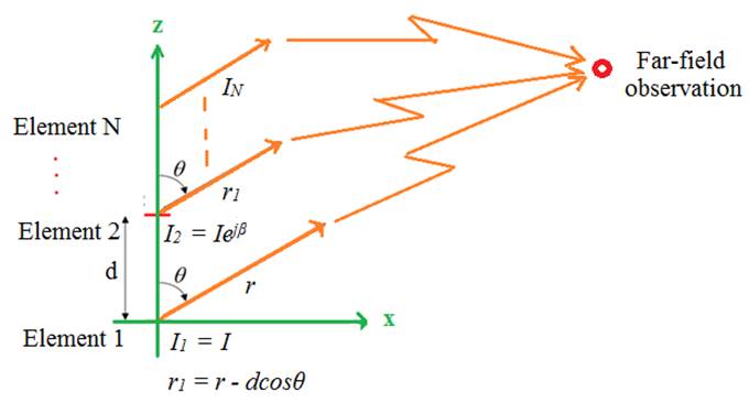
The two Hertzian dipoles of length dℓ separated by a distance d and excited by currents with equal amplitude (I) but a phase difference of ( from 0 to 2). Let a far-zone electric field, Eant_1, with current, I1, is produced by antenna 1 and similarly, far-zone electric field, Eant_2, with current, I2, by antenna 2, then the fields are:
Where
For far field observer, the distances can be approximated as follows
Keeping this information, the total electric field can be written as the sum of the individual fields:
Hence, we can see the total far-field radiation pattern, |Etot|, of the array consists of the original radiation pattern of a single dipole multiplying with the magnitude of the Array Factor |AF|. In practical antenna array, the element radiation pattern is chosen to be non-directional. Therefore, the array radiation pattern will be totally determined by the AF alone and when we plot in decibels, the power and field patterns look exactly the same.
In the x-y plane, the array far-field functions for the elliptical antenna array, Zare (2012), are:
If the center of an ellipse is located at the origin on the x-y plane, then the parametric equation of ellipse in the rectangular coordinate system is given by
Where the a and b are the semi-major axis and semi-minor axis, respectively, and ϕ is the angle between positive section of x-axis and a point (x,y) of the ellipse in the x-y plane, Also the ellipse eccentricity e can be defined as:
c is the half of the distance between two focuses, thus for an elliptical N-element array with its center in origin of x-y plane, we have:
is the angle in the x-y plane between the x-axis and the nth element. Thus, the array factor can be written in the form of
The geometrical arrangement of the antenna array is shown in Figure 2. The far field of the antenna is described using the AF. The AF of the proposed antenna is the combination of linear arrays and elliptical arrays.
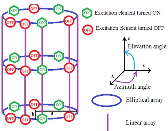
The main problem of the inter-coupling effect reduction is to calculate the exact locations and inter-elements spacings. In the geometrical shape of Figure 2, the angel theta (Ɵ) is extended between the z-axis and y-axis and the angle phi (ϕ) is extended circling the z-axis between x-axis and y- axis
2.1. Antenna performance measurement
The performance of the proposed antenna design is evaluated using the SLL and the FNBW. Both the SLL and directivity are closely related to the AF of the proposed antenna. Directivity of an antenna is the ratio of the radiation intensity in a given direction from the antenna to the radiation intensity averaged over all directions. An antenna that radiates equally in all directions would have effectively zero directionality, and the directivity of this type of antenna would be 1 (or 0 dB). Directivity of a non-isotropic source is the ratio of its radiation intensity in a given direction over that of an isotropic source.
Mathematically:
If the direction is not specified, it implies the direction of maximum radiation intensity (maximum directivity) expressed as
Where
D |
is the directivity and |
Diso |
is the maximum directivity (i.e. dimensionless quantity) |
Uinst |
is the instantaneous radiation intensity (Watts per unit solid angle) |
Umax |
is the maximum radiation intensity (Watts per unit solid angle) |
Uiso |
is the radiation intensity of isotropic source (Watts per unit solid angle) |
Pradiated |
is the total radiated power (Watts) |
For anisotropic source, the directivity is unity since Umax, and Uiso are equal to each other.
With B0 is the magnitude of the radiation, the total radiated power is calculated as
The general expression for the directivity and maximum directivity are, respectively, written as
Where the Normalized Array Factor (AF) is the ratio of the instantaneous value of the array factor to the maximum value of the array factor
2.2. Geometric configuration of the antenna
As it is shown in Figure 2, the geometrical configuration of elliptical cylindrical antenna array is constructed from a linear antenna array directed towards the +Z-axis and elliptical antenna array encircling the Z- axis with the linear arrays extending on the surface. As the far-field pattern is described by the AF of the antenna array, the total AF of the proposed antenna is the multiplication of the linear array factor
Where, the linear and elliptical array factors are described in the following equations, respectively
Then, the whole array factor results into the ECAA:
Where
An is the excitation amplitude of the nth element of the elliptical component
Am is the excitation currents of the mth element of the linear array
A linear antenna array of M isotropic elements positioned parallel to the z-axis and are separated by a distance dv. The amplitude excitation of each element is Am and there exists a progressive phase excitation Pm between the elements. β is the angle between the axis of the array (z-axis) and the radial vector from the origin to the observation point.
Where
Where, the terms
As it can be shown in Figure 3, the SLL is measured as the AF value at the first SLL. An antenna can have multiple SLLs and the maximum SLL is the first SLL which negatively influences the communication. The less the SLL the more the gain, the less the power wastage and the less the interference.
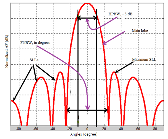
The second antenna performance measuring parameter is the FNBW which is measured in degrees. It is the range of angles where the first nulls of the main beam start. This determines the directivity of the radiation characteristics. The less the angle of the FNBW the more the antenna would be directive which provides better resistance to un desired signal interference.
3. Inter-coupling reduction using beamforming
Beamforming (BF) enables signals to add constructively and cancel destructively. This helps to increase the signal intensity in the intended direction while reducing the interfering directions. This both increases the gain of the signal and decreases the power wastage in the undesired direction. The directivity of the radiation pattern will also increase which in turn increases the signal fidelity.
Hyper beamforming is generated from the difference and addition
Now, total equation of the hyper beam is formed as a function of the hyper beam exponent, k as:
Where the difference and sum of the radiation patterns are calculated from the AF of the proposed antenna:
Where
DBeam = |
Left Beam (LeftBeam) minus Right Beam (RightBeam) |
SumBeam = |
LeftBeam + RightBeam |
AF = |
far field at the elevation and azimuthal angles, Ɵ and φ, respectively |
Cmn = |
amplitudes of the AF with m represents the linear array elements & n represents the elliptical arrays elements. |
M & N = |
maximum number elements in the linear and elliptical directions, respectively. |
w = |
wavenumber. |
4. System model
The inter-coupling effect introduces interference and wastage of power. The inter-coupling reduction mechanism can be achieved by proper inter-element spacing design and proper thinning. If the inter-element separation increases the inter-coupling effect decreases, however, it results in to unnecessary increase in the size of the antenna. Hence, the inter-coupling reduction should take the size of the antenna, SLL reduction and directivity increase in to consideration. This can be achieved by automating the design of the antenna using an optimization algorithm.
4.1. Inter-coupling reduction using optimization algorithms
The PSO is used as an optimization algorithm with the objective function to reduce the inter-coupling effects. The PSO works in the manner that some birds (called particles in general) are competing for food moving at their own speeds. It also moves to a certain position and at this position each bird measures the amount of food it gets in its own speed (objective function). The bird shares its experience to the rest of the birds and every bird updates their speed and position according to the best value gained by any of the birds.
The pseudocode of the PSO birds experience referred as particles is given by:
1. For each particle
2. Initialize maximum iteration
3. Initialize population size
4. end
5. While maximum iteration is not attained
6. Do
7. Every particle calculates its fitness
8. If current fitness > old private fitness
9. Private best fitness = private current fitness
10. End
11. Compare the global best fitness
12. Update the position and speed
13. End
Similarly, the pseudo code of the of the GA is:
1. Generate initial population
2. Compute fitness
3. While population has not converged
4. Do
5. Selection
6. Crossover
7. Mutation
8. Compute fitness
9. End
Another heuristic algorithm (SaDE) has a smaller number of control parameters and the parameters adapts itself to facilitate the learning. This algorithm has shown better convergence speed and reliability compared to PSO and GA, described in Bian et al. (2015), Lema et al. (2016), Panduro et al. (2006), and Singh and Salgotra (2017).
4.2. Inter-coupling reduction using SLL attenuation
In addition to the optimization, the inter-coupling effect reduction using SLL attenuation has integrated. Similar to electrical filters the SLL attenuation reduces the SLL without affecting the main lobe. The usual bandpass filter selects a certain frequency bands while rejecting the rest spectrum and similarly the proposed technique attenuates the SLL which increases the gain of the antenna. The inter-coupling effect reduction technique has an attenuation factors α, such that 0 < α < 1. The simplified form of the algorithm is given in Figure 4.
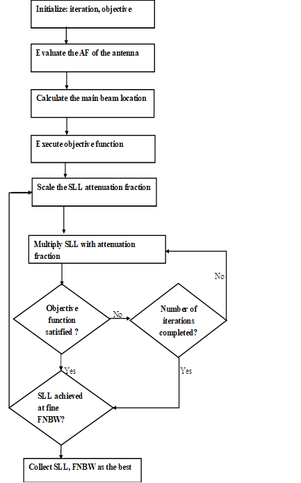
The algorithm continues executing as far as the maximum number of iterations are not finished. Besides, the algorithm attenuates the SLL before transmission and before the required SLL level is achieved. The SLL level can depend on the quality of service the antenna is being used. Stringent Inter-coupling reduction requiring services are investigated in this paper like for satellite communication applications.
5. Result and discussion
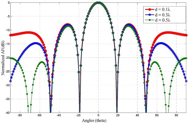
5.1. Effect of the inter-element spacing on the antenna performance
As it is shown in Figure 5, the SLL decreases when the electrical size increases. more specifically, the 0.5λ has shown better SLL reduction than 0.1λ and 0.3λ. The reason for this decreasing in the SLL is because the inter-element spacing increases which results in less inter-coupling effect.
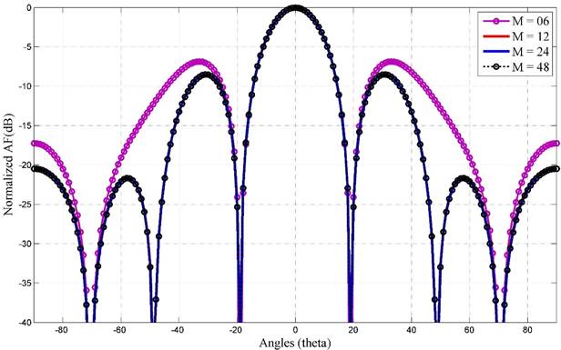
5.2. Effect of the number of elements on each elliptical ring on the antenna performance
The number of elements on each elliptical ring is varied as shown in Figure 6. The antenna has using three elliptical rings and on each ring the number of elements is varied to evaluate the inter-coupling effect of the density of the elements. When the number of elements on each ring (M) varies from 06 to 12, the SLL reduction has increased. However, when the M varies from 12 to 48, the SLL is not almost no varying. This is because as the number of elements increase the intensity of the signal strength increase, however, at the same time the inter-coupling effect also increases which leads to almost invariable in the SLL reduction.
Hence, increasing the number of elements more than 12 is not recommended on this type of antenna design. Increasing the number of elements, in general, increases the SLL reduction but the increase in coupling effect again negatively affects the antenna performance.
5.3. Inter-coupling reduction using optimization and hyper beamforming
In this paper, for better inter-coupling reduction, the thinning, optimization and SLL reduction mechanisms are integrated together. The design challenge is to identify which elements should be turned ON, the location of the element and the inter-element spacing. Once the position of the candidate turned on array elements that results in to the best inter-coupling reduction mechanism are identified the rest of the array elements can be turned off or removed. Hence, the proposed antenna design technique is used to identify the exact location of the elements (that should be turned on) which results in to the best SLL reduction and directivity enhancement using the inter-coupling reduction mechanism. The AF of the design is shown in Figure 7.
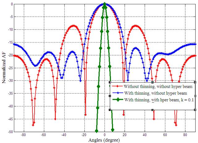
Using the thinning, Figure 7 is simulated with only 17 elements are turned ON out of the 36 total elements. One of the inter-coupling reduction mechanism using thinning has shown better SLL reduction compared to the uniformly excited array elements, shown in Figure 7. Furthermore, with 0.3 hyper beam exponent the inter-coupling effect has reduced significantly. Further SLL reduction is also achieved by further reducing the hyper beam exponent to 0.1.
From Figure 8, we can observe that the inter-coupling reduction is possible using hyper beam exponent variation. This inter-coupling reduction is evaluated by turning only 15 ON using the thinning. From the results we can conclude that the thinned design has better SLL reduction than the fully populated design. By further integrating the hyper beamforming (hyper beam exponent of 0.2 and 0.1) to the without thinning and with thinning design, the optimized antenna design resulted in to better inter-coupling reduction than the not optimized (not thinned), with the same hyper beam exponent values.
Even though Figure 7 has more inter-coupling reduction than Figure 8, Figure 8 has a greater number of turned ON elements which results in more power wastage than Figure 7. Hence, the amount of thinning should be properly designed and optimized as further increase in the number turned-OFF elements reduces the radiation intensity.
5.4. Inter-coupling reduction using SLL attenuation
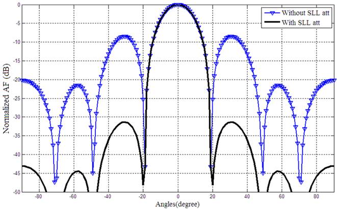
To reduce the inter-coupling effects, the SLL decreasing mechanism (SLL att) is studied in addition to the optimization and the hyper beam techniques. The inter-coupling reduction is integrated with the heuristic algorithm. Figure 9 indicates that this technique reduces the SLL and increases directivity (FNBW). The inter-coupling reduction using SLL attenuation reduces the SLL from - 8.5dB to -30dB, shown in Figure 9. The results shown in Figure 9 are evaluated with uniformly excitation weights of the antenna. This uniformly excited indicates that there is no thinning in the antenna.
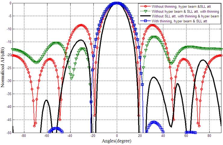
Using the thinning, 17 out of 36 elements are turned ON, shown in Figure 10. At hyper exponent of 0.5, the SLL has reduced from -27.98 to -45.37dB. This SLL reduction is improved by integrating the inter-coupling effects reduction technique proposed in this work. The SLL reduction is further reduced to -47dB by integrating the thinning, beam forming and SLL attenuation, as shown in Figure 10.
5.5. The impact of inter-coupling reduction on antenna performance
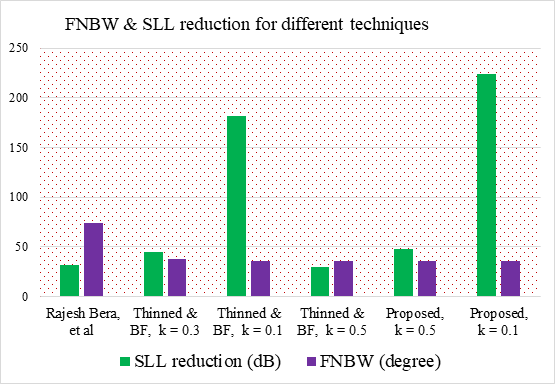
Different techniques have implemented to reduce the inter-coupling effects which in turn reduces the SLL and power wastage. The experiment number (Ex. No.) 1 is designed using PSO [17]. Ex. No. 2, 3, 4, 5, and 6 are evaluated in this paper. The proposed integrated technique (thinning, beamforming and SLL attenuation) results in much better SLL reduction than the state of the arts. From Table 1, we can observe that the FNBW has decreased from 74.12o to 36o in this paper. This indicates that significant directivity enhancement is also achieved.
Table 1 Comparison of SLL and beam width.
| Exp. | Antenna designing technique | Thinned | SLL (dB) | FNBW (deg) |
|---|---|---|---|---|
| 1 | Bera et al., 2014 | 17 | -31.7 | 74.1 |
| 2 | Thinned and BF, k = 0.3 | 17 | -44.4 | 38 |
| 3 | Thinned and BF, k = 0.1 | 17 | -182.1 | 36 |
| 4 | Thinned and BF, k = 0.5 | 17 | -30.0 | 36 |
| 5 | Inter-coupling reduction using SLL reduction, thinned, and BF, k = 0.5 (proposed) | 17 | -47.6 | 36 |
| 6 | Inter-coupling reduction using SLL reduction, thinned, and BF, k = 0.1 (proposed) | 17 | -224 | 36 |
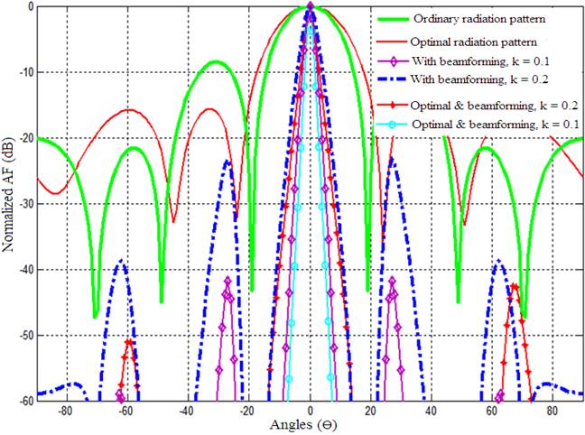
From Figure 11, we can observe that the SLL reduction increases when the optimization, thinning and SLL attenuation work together. It is also shown that the smaller the hyper beam exponent (k) the more the SLL reduction.
To sum up, the proposed integrated technique has resulted in better SLL reduction and directivity. Besides, 42.3dB more SLL reduction is achieved compared to the work done by Lema et al. (2016). On the other hand, the thinning reduces the power significantly and hence more energy efficiency is possible as a crosscutting theme. Though the combination of many techniques introduces moderate computational complexity, the radiation characteristics of the antenna has significantly enhanced. Hence, with little more computational complexity trade-off, significant SLL reduction, energy efficiency, directivity enhancement, and better signal fidelity are possible with the proposed technique.
6. Conclusion
In this paper, the thinning, beamforming and inter-coupling reduction using SLL attenuation techniques are discussed. The thinned antenna design has resulted in much better SLL reduction than the antenna design without thinning. The tradeoffs, the thinning and the size of the antenna are discussed. From the simulation results, it is observed that the SLL reduction, increasing directivity and reducing power wastage are achievable using the proposed integrated technique. Hence, the proposed inter-coupling reduction method is ideal for better radiation characteristic antenna design.

