


 text new page (beta)
 English (pdf)
 Article in xml format
 Article references
 Send this article by e-mail
 Cited by SciELO
  Similars in
SciELO
Similars in
SciELO 
 Permalink
1. Introduction
Metals are the most widely used materials in armour design. The main advantage with metals is that, they are capable of carrying structural loads while provide efficient protection. The most commonly used metallic material in armoured fighting vehicles is steel. The main properties such as toughness, hardness, good fatigue strength, ease of fabrication and joining makes it a popular material for armoured vehicle. At present, steel accounts for half the weight of tank armour (Lakowski). Therefore, reduction in the cost of steel will reduce the overall cost of armoured vehicles. Usually steels for armour application are produced by conventional ingot casting route. This has incited an interest to explore other steel manufacturing processes in order to reduce the cost of steel.
Today continuous casting is the preferred choice in steel making plants. The continuous casting process is much more advantageous than the conventional ingot casting route in terms of productivity, yield, energy and labor efficiency and quality assurance (Brimacombe, 1993, Mizoguchi, Ohashi & Saeki, 1981, Okumura, 1994). In conventional ingot making, steel is cast to ingot and then rolled to slabs followed by rolling into different size plates. Continuous casting process replaces separate steps of ingot casting like ingot making, mold stripping, soaking and primary rolling with one operation and thus trims down the production cost. However, center macro segregation is one of the most significant defects in continuous casting of steels. The mechanical properties of steels are strongly affected by the segregation of alloying elements. This type of segregation causes banding microstructures through the rolled plate. The banding microstructure becomes sites for strain localization and facilitates easy crack formation. Thus, it renders the steel undesirable for ballistic protection applications. Soft reduction of the strand in the final stages of solidification has been employed successfully for suppressing the center segregation in continuous cast steels (El-Bealy, 2014, Thome & Harste, 2006).
Rolled homogeneous armour (RHA) steels possess a good combination of strength and ductility and are used as armour to prevent brittle fracture. Moreover, RHA steels are the major material employed for the manufacturing of combat vehicles (Atapek, 2012, Hu, Lee & Chen, 2002). Previous studies have extensively investigated the ballistic behaviour of RHA steels and the results are well documented. Hu, Lee and Chen (2002) studied the different modes of penetration in modified rolled homogeneous armour steel. Transformed adiabatic shear bands (ASB) are reported adjacent to the penetration cavity in this study. Adiabatic heating directed plastic deformation and failure in RHA steel at dynamic loading is investigated by Bassim, Odeshi and Bolduc (2009). Microstructural observations pertaining to the perforation of RHA steel with shaped charge jets has been presented by Raftenberg and Krause (1999). The observations include adiabatic shear banding, fracture associated with shear bands and melting at the adjacent perforated areas. In a recent study, ballistic performance of RHA steel against long rod penetrator was investigated by Senthil, Singh, Siva Kumar and Gogia (2015). It was concluded that the target deformation behaviour has considerable influence on the penetration velocity of the projectile. However, limited literature is available on ballistic behaviour of RHA steel plates against medium caliber projectiles. Medium caliber ammunitions e.g. 20-40 mm armour piercing (AP) ammunitions are used to enable effective engagement of fast aerial targets. Medium caliber ammunitions are also used against armoured vehicles and fortified bunkers.
The present study illustrates the production of RHA steel by continuous casting route. The tensile and impact properties of the continuously cast RHA steel has been evaluated for different thickness plates. The ballistic performance of 30 mm thick plates against 30 mm medium caliber armour piercing (AP) steel projectile is presented in this study. Related damage and deformation patterns of the RHA steel have also been analyzed.
2. Steel production
The RHA steel plates of different thicknesses were produced at JINDAL Steel plant, Angul, Orissa. The process layout for the production of steel is shown in Fig. 1. Steel production started with melting directly reduced iron (DRI) in an electric arc furnace. Other raw materials include in plant scrap and the fluxes like lime and dolomite for making slag. The molten metal was transferred to a ladle furnace for final refining and was further subjected to vacuum degassing to minimise Hydrogen and other impurities. Table 1 illustrates the analysed final chemical composition of the steel.
Table 1 Analysed chemical composition of RHA steel produced by continuous casting route.
| Elements | Weight Percentage |
| C | 0.31 |
| Cr | 1.43 |
| Ni | 1.64 |
| Mn | 0.44 |
| Mo | 0.45 |
| Si | 0.17 |
| P | 0.0035 |
| S | 0.0007 |
| Fe | Balance |
Subsequently, 300 mm thick and 2000 mm width slabs were continuously cast from the molten steel through a single strand slab caster. The slabs were subjected to mechanical soft reduction (MSR) in the final stages of solidification in order to suppress the centreline segregation. The soft reduction process is displayed in Fig. 2. The slabs were allowed to cool for 48 hours in the slab yard. The slabs were hot rolled at 1200-1250(C to desired thicknesses in a four high reversible plate rolling mill. In order to maintain the plate surface quality high pressure de-scaling units were employed during rolling operation.
Upon completion of rolling, the plates were subjected to heat treatment to obtain the final properties. The plates were austenitized at 910°C and soaked for appropriate time depending on the thickness of the plate. Subsequently, the plates were water quenched in a roller quenching machine and immediately tempered at 650°C, followed by cooling to room temperature in air. RHA steel plates with 5 different thicknesses i.e. 20,30,40,50 and 80 mm were produced by continuous casting route.
3. Experimental setup
For depicting the macrostructure, steel specimens were macro etched by keeping it in a 50% Hydrochloric acid solution at 80°C temperature for 30 minutes. For microstructure characterization, specimens were prepared following standard metallographic techniques used for steels. All the samples were etched using 2% Nital (2 ml Nitric acid and 98 ml Methyl Alcohol) to reveal the microstructure. Microstructures were examined using optical and scanning electron microscope (OM and SEM). The X-ray diffraction (XRD) studies of bulk samples were carried out using a Philips 3020 diffractometer with CuKα radiation for determining the different phases present in the steel.
Cylindrical tensile specimens were machined from the heat treated plates along the longitudinal axis of the rolled plate. The size and geometry of the specimens as well as the testing procedure are in accordance with ASTM E8-04 (2004). The specimens were tested under tension at a strain rate of 4.8x10⁻¹s-1 using an Instron Universal Testing machine (Instron 5500R). Three samples for each thickness were taken and tested at room temperature. The mechanical properties, such as yield strength (σYS), ultimate tensile strength (σUTS), percentage elongation (%El) were calculated from the load-elongation curves obtained from the tensile testing. Vickers hardness number values of all the plates were measured according to ASTM E92-17 (2017).
Standard charpy V-notch (CVN) specimens (10×10×55 mm size) were made as per ASTM E23-02a (2002) and the tests were carried out to find out the impact properties. Three samples for each thickness were tested and their average value was taken as the impact value. Following the charpy impact testing, the fracture surfaces of selected broken impact specimen were studied by using a FEI scanning electron microscope.
Plates of 1220x1220x30 mm size were cut from a single plate and subjected to ballistic evaluation. Ballistic evaluation of the plates was carried out by impacting with 30 mm armour piercing (AP) projectiles fired from a BMP-2 gun. The hardness of the projectile is measured to be 690 HV. The angle of attack was normal to the target. The distance of the target from the gun was 75 meters. The striking velocity of the projectiles were measured using infrared light emitting diode photo voltaic cells by measuring the time interval between the interceptions caused by the projectile running across two transverse beams kept at a fixed distance apart. The measured impact velocity was 460±20 m/s. The ballistic testing arrangement is shown schematically in Fig. 3. The projectile is displayed in Fig. 4. After ballistic testing, the impacted craters were cut into half and subjected to standard metallographic procedure to reveal the post ballistic microstructures.
4. Results and discussion
The macrostructure of an 80 mm thick continuous cast plate is illustrated in Fig. 5. It shows a uniform structure throughout the thickness of the plate. The macrostructure does not reveal the presence of any central line segregation. This is essential; otherwise the material cannot be used for armour application. It indicates towards the significance of MSR process in obtaining a homogeneous structure. Fig. 6(a) exhibits the optical micrographs of 30 mm thick plates produced by continuous casting route. Optical microstructure of a plate produced by ingot casting route is presented in Fig. 6(b) . Tempered martensitic structure is noticed in both the plates. The presence of martensitic structure in the continuous cast steel plates is further substantiated from the scanning electron micrographs (Fig. 7 a ) and XRD patterns (Fig. 7 b ). The SEM micrographs show prominent martensitic structure. In addition, only martensitic peaks are obtained from the XRD analysis of the plates. Similar microstructure is observed for all the plates with different thicknesses produced by continuous casting route. This suggests that the employed heat treatment and subsequent cooling is sufficient to produce a martensitic microstructure in all the different thickness plates. It is to be noted that martensitic phase is the most desirable structure for ballistic resistance applications (Bhat, 1984, Jena, Siva Kumar, Rama Krishna & Bhat, 2008).
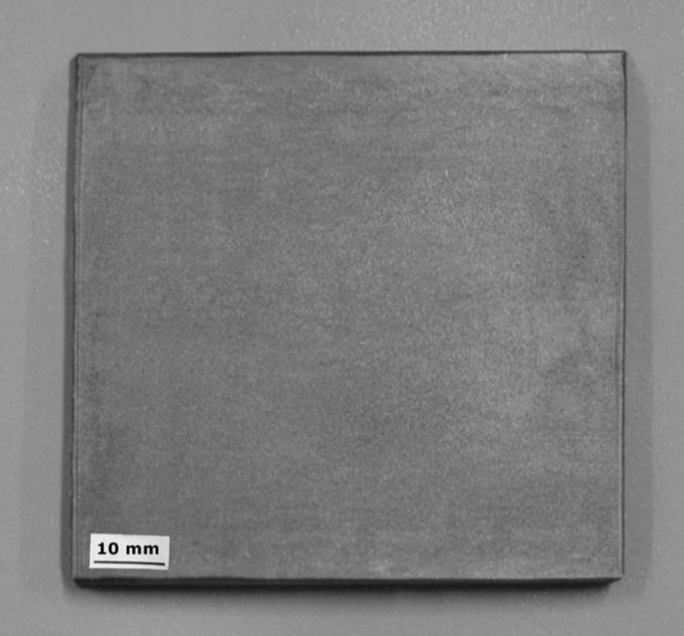
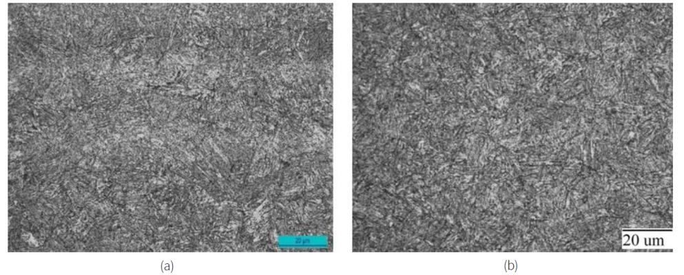
Figure 6 Optical microstructures of RHA steel plates produced by (a) continuouscasting route and (b) ingot casting route.
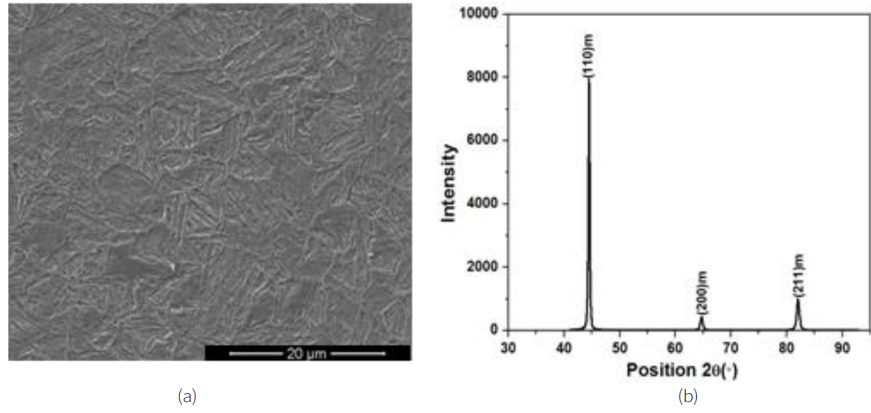
Figure 7 (a) SEM micrographs and (b) X-ray diffraction pattern of 30 mm RHA steel plates produced by continuous casting route.
Table 2 illustrates the mechanical properties of all the different thickness plates produced by continuous casting route. All the plates show similar level of strength, hardness and elongation. Yield strength and ultimate tensile strength of the plates lie in the range of 982-1025 and 1074-1128 MPa, respectively. At the same time, hardness values of the plates lie in the range of 291-319 VHN. In addition, elongation of around 16% is observed for all the plates. The charpy impact energy values of the plates lie in the range of 113-143 J at room temperature and 100-115J at -40°C. The mechanical properties of 30 mm thick RHA steel produced by conventional ingot casting route are also included in Table 2 for comparing the properties obtained by continuous casting route. It can be contemplated that properties attained by continuous casting route are in the similar range to those of the properties of the material produced by typical ingot casting route.
Table 2 Mechanical properties of different thickness RHA steel plates produced by continuous casting route. Mechanical properties of 30 mm RHA steel plates produced by ingot casting route are also included.
| Production Route | Thickness (mm) | YS (MPa) | UTS (MPa) | Percentage Elongation | Hardness (VHN) | CVN (J) | |
| RT | -40°C | ||||||
| Continuous casting | 20 | 1022±3 | 1112±16 | 15.7 | 303±8 | 133±1 | 115±3 |
| 30 | 1019±1 | 1081±3 | 16.1 | 301±5 | 143±6 | 114±7 | |
| 40 | 1000±6 | 1092±2 | 16.0 | 310±9 | 129±11 | 109±4 | |
| 50 | 986±4 | 1080±6 | 15.8 | 305±14 | 137±8 | 104±6 | |
| 80 | 1017±2 | 1095±8 | 15.6 | 302±8 | 113±3 | 100±11 | |
| Ingot Casting | 30 | 993±5 | 1060±8 | 16.8 | 303±3 | 130±7 | 90±8 |
Fig. 8 elucidates the scanning electron micrograph of the fracture surface of the broken charpy impact samples of 30 mm thick plates produced by continuous casting route. Dimples with a fairly wide variation in shape and size can be observed on the fracture surface. The dimple-like morphology of the fracture surface suggests towards a ductile mode of failure, which is a desirable criterion for armour materials in order to increase the absorption of impact energy.
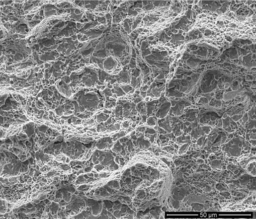
Fig. 9 summarises the ballistic performance of 30 mm thick plates produced by continuous casting and ingot casting route. Ballistic performance of the plates was measured using the depth of penetration (DOP) method (Jena, Mishra, Ramesh Babu, Arvindha Babu, Singh, SivaKumar & Bhat, 2010). The ballistic results of the RHA steel produced by both the processes are similar. A macroscopic comparison of the plates produced by continuous casting route and ingot casting route after ballistic impact are shown in Fig. 10(a) and (b). A close view of the impacted region in the front and rear of the target plates is given in Fig. 10(c) - (f) . It can be seen that the projectile has made ductile holes in the front face of the impacted target plates during the penetration process. At the same time, a smooth bulge can be seen at the rear side of the impacted plates. Ductile hole growth is the common mechanism of crater formation observed in metallic materials. The lateral expansion of the crater occurs by the radial and circumferential stresses generated during the entry of the projectile into the target material. The average diameter of the craters at the front face is measured to be 46 mm. There are no cracks detected in the impacted plates. The damage region features in the front and rear of the target plates implies a good ductility and impact toughness of the target plates.
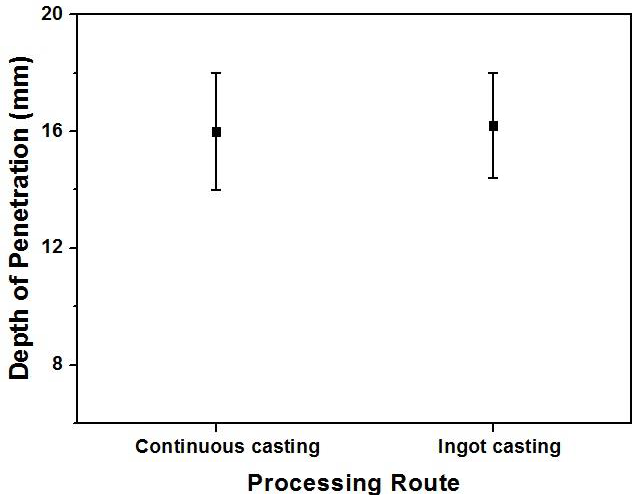
Figure 9 Comparison of ballistic performance of 30 mm RHA steel plates produced by continuous casting and ingot casting.
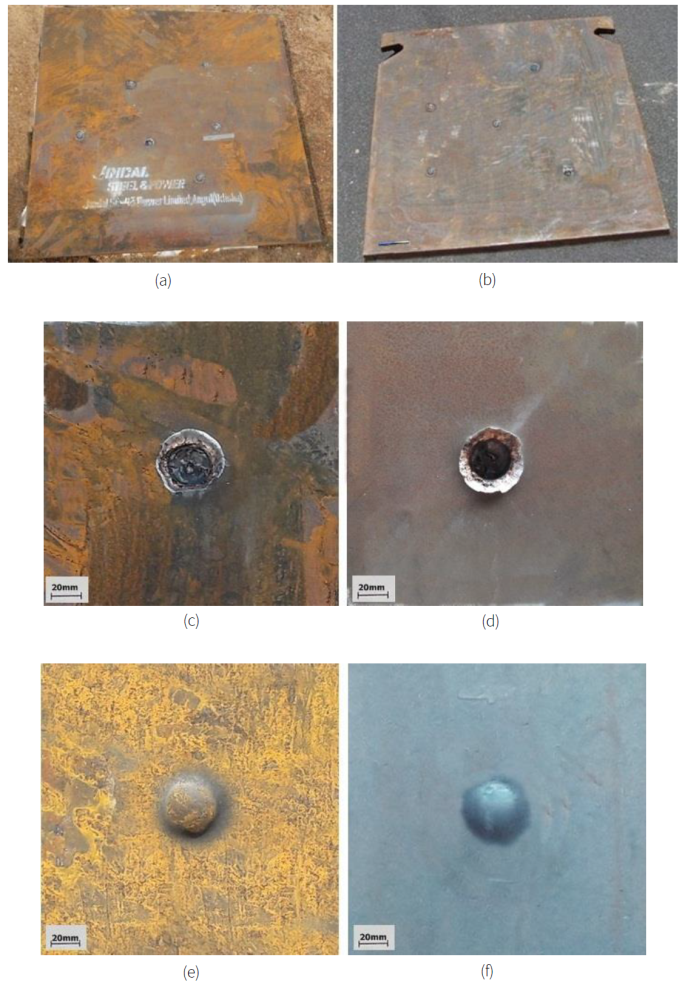
Figure 10 (a) Front view of the continuous cast RHA steel plates after ballistic impact. (b) Front view of the ingot cast RHA steel plates after ballistic impact. (c) A close view of the front damage of continuous cast RHA steel plate. (d) A close view of the front damage of ingot cast RHA steel plate. (e) A close view of the rear damage of continuous cast RHA steel plate. (f) A close view of the rear damage of ingot cast RHA steel plate.
The impacted projectiles are collected after ballistic testing and a representative projectile is displayed in Fig. 11(a) . It is observed that the projectiles are not fractured. This can be ascribed to the high hardness of the projectiles in comparison to the target plates. Fig. 11(b) exhibits a small piece of the target material removed from the front face of the target plate during ballistic impact. Light and dark blue colour shades are detected on its surface. When a projectile strikes a target material, heat is generated at the point of impact due to friction and material deformation. It leads to the formation of an oxide film on the surface of the steel and a change in colour. The change in colour of steel gives a good indication of the amount of heat generated during ballistic impact. It is to be noted that dark blue colour defines a temperature rise of 295°C and light blue colour indicates a temperature rise of 310°C (Rajan, Sharma & Sharma, 1998).
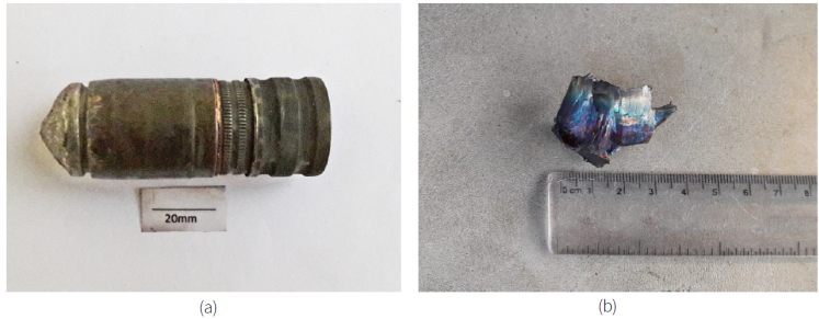
Figure 11 (a) Unbroken 30mm AP projectiles after ballistic impact. (b) Fractured RHA steel pieces from the front face of the plate after ballistic.
The broken steel pieces are subjected to fractographic analysis and a representative fracture surface is shown in Fig. 12(a) . Small elongated dimples are observed all over the fracture surface. This shear dimple morphology indicates that the final failure of the material takes place by a shearing process. Similar fracture morphology in ballistic impact studies has also been reported previously (Mishra, Jena, Ramakrishna, Bhat & Gupta, 2012). Fig. 12(b) shows the smooth smeared fracture surfaces created by the rubbing action of the pieces during the fracture process. The formation of smeared fracture surfaces can be explained by simultaneous effect of local rise in temperature and generated shear strain.
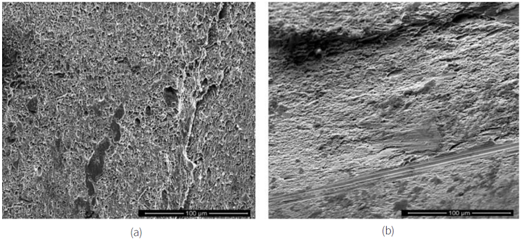
Figure 12 SEM fractographs of the fractured RHA steel pieces after ballistic testing. (a) Shear dimples in the fracture surface. (b) Smooth fracture surfaces indicated by small arrows.
The post ballistic microstructures of the impacted plate are given in Fig. 13. Smooth material flow lines bent in the direction of projectile impact is noticed from the microstructures (Fig. 13 a-b ). White etched adiabatic shear bands (ASB) are observed adjacent to the crater walls, Fig. 13(b) . Fig. 13(c) displays formation of branches in an ASB. Scanning electron micrograph illustrating ASB leading to crack formation is shown in Fig. 13(d) . Ballistic impact involves extremely large strains with material flow adjacent to the impacted region. Formation of ASB takes place as a result of thermo-mechanical instability caused by deformation mechanisms at such high strain rates (Lee et al., 1995, Timothy, 1987). It is well known that cracks are originated from ASBs (Jena, Jagtap, Siva Kumar & Bhat, 2010). This facilitates in the fragmentation and removal of material at the front face of the target plate.
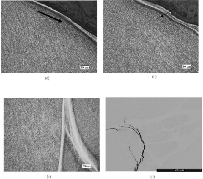
Figure 13 Post ballistic microstructure adjacent to the crater. (a) deformed material flow lines. (b) transformed ASB at the edge of the crater. (c) ASB with branches. (d) SEM micrograph showing origin of cracks from ASB.
Post ballistic microstructures of the steel pieces removed from the front face of the target material is also carried out and is shown in Fig. 14. The microstructure elucidates wavy material flow lines and ASBs in these steel pieces. Shear strain developed in these steel pieces during ballistic impact is calculated by taking the angular deflection (γ=tanθ) from the microstructural features (Meyers & Witman, 1990, Xu, Zhong, Chen, Shen, Liu & Bai, 2001). The true strain on these steel pieces is also determined by employing the following formula.
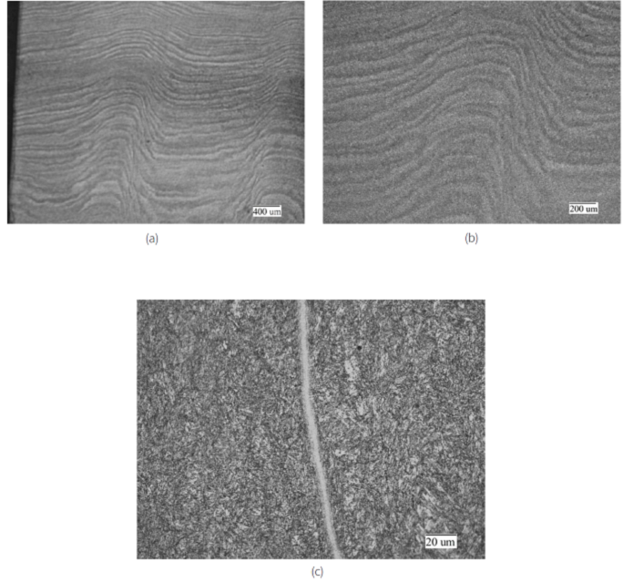
Figure 14 Post ballistic microstructure of broken steel pieces from the front face of the plate. (a) Wave shaped deformed flow lines. (b) Close view of the deformed flow lines. (c) ASB near to the surface.
Where, ε = True strain and γ= Shear strain. The generated shear strain and true strain on these steel pieces is measured to be 0.55 and 0.31 respectively. The measured shear strain and true strain values closely match with the previously reported values in similar steel (Mishra, Jena, Ramakrishna, Bhat & Gupta, 2012).
5. Conclusions
RHA steel plates of different thicknesses in the range of 20-80 mm are produced through continuous casting route. The produced steel exhibits a uniform martensitic structure and a very good combination of strength, hardness, elongation and impact toughness. The mechanical and ballistic properties of the continuous cast steel are identical with steel produced through ingot casting route. The ballistic penetration process is seen to consist of material deformation, ASB induced crack formation and eventual material removal from the impact face.

