


 nueva página del texto (beta)
 Inglés (pdf)
 Artículo en XML
 Referencias del artículo
 Enviar artículo por email
 Citado por SciELO
  Similares en
SciELO
Similares en
SciELO 
 Permalink
1. Introduction
Long term utilization of fossil fuels has depleted their availability and there is a quest towards new energy resources. Renewable energy sources like wind, solar energy, and tidal energy will be a solution for this. Of all these energies solar energy is the cheap and abundant power available. The linear and unstable nature of PV array inhibits maximum production of power. Therefore a suitable DC-DC converter and MPPT controller is required to obtain maximum power. The poor conversion efficiency of PV system is improved by MPPT technique. The maximum power at a given temperature and irradiation at which the PV array produces maximum output power is determined by MPPT technique (Kanimozhi & Rabi, 2017a).
The necessity of MPPT control method in PV system is to ensure the tracking of maximum available power obtained from the PV panel. A review on MPPT control techniques is given in (Bhatnagar & Nema, 2013). Different approaches have been reported in literature such as look up table method (Park & Yu, 2004), hill-climbing (Xiao & Dunford, 2004), Perturb & Observe (P&O) method (Femia, Petrone, Spaguonola, & Vitell, 2005), improved P&O (Dasgupta, Pandey, & Mukerjee, 2008),increment conductance method (Yu, Jung, Choi, & Kim, 2004), fuzzy based method (Altas & Sharaf, 2008) near-MPP operation (Huang, Sun, & Ho, 2006) and Neural-network (Liu, Liu, Huang, & Chen, 2013), constant voltage method (Kobayashi, Matsuo, & Sekin, 2006), β method (Jain & Agarwal 2004), system oscillation method (Hussein & Batarseh 2011), and ripple correlation method (Chen, Young, Chu, & Liu, 2011).Sliding mode control is adopted to track the MPP in (Mamarelis, Petrone, & Spagunuolo, 2013). Here the reference current is used for control law synthesis which may lead to a lack of robustness to operation conditions (Kanimozhi & Shunmughalatha, 2015).
The efficiency of PV system depends on the selection of DC-DC converter (Kanimozhi & Rabi, 2017b).Various DC-DC converters used in PV system are analyzed by many researches earlier. The converters are classified based on application, nature of switching, modes of operation, etc. The basic circuit models of DC-DC converters are buck, boost, buck-boost, Sepic , Cuk and Zeta converters. The basic buck converter used for battery charging, operated under high switching frequencies results in high switching losses, noises, and component stresses (Chuang, 2010). Hence power reduction and deterioration affects the performance of buck converter. A non inverting synchronous buck boost converter experiences switching voltage stress. Voltage stress is the sum of on state voltage blocking levels and current levels occurring in active switches (Sahu & Rincón-Mora 2004). The approaches in literature have the problem of switching loss and switch voltage stress. Switch voltage stress also depends on topology of the circuit.
Research on modification of conventional Cuk circuit has been done for lowering switching or conduction loss, reducing component sizes, improving converter efficiency, reducing voltage or current stress, speeding up transient responses, etc. An approach for generation of Various Cuk and other DC-DC converters has been generated based on synchronous switch scheme. (Wu & Liang 2001). Soft switching Cuk and other converters can be created with new synthesis procedure.
The maximum power producing efficiency of the PV system in terms of faster convergence and stability mainly depends on the choice DC-DC converter .In order to reduce the problems described above lossless soft switching technique is introduced. The classification of soft switching technique is: 1. Passive soft switching 2. Active soft switching. In passive technique passive components perform switching. In active technique both active switches and passive components perform switching operation. Considering the cost and performance passive soft switching technique is implemented in various low power applications .
Passive methods do not require an extra switch or additional control circuitry. They are less expensive, have higher reliability and have been reported to achieve higher performance than active methods (Yun, Choe, Hwang, Park, & Kang, 2012). For PWM converters, zero current turn on and zero voltage turn off are achieved by passive soft switching technique that reduces switching losses (Wu, Chang, & Yang, 2012).
The disadvantage of Sliding mode(SM) controlled SEPIC converter for MPPT PV applications (Mamaralis, Petrone, & Spagunuolo, 2014) is that its output ripple current will swing over a wide range resulting in a poor power tracking and efficiency.
In the proposed work, a passive soft switched Cuk converter is designed to reduce the conduction losses and voltage stress in switch. A MPPT controller is designed by formulating a sliding surface. The sliding surface is designed in order to attain a robust MPPT approach. The approach is proved to be robust by investigating the performance in the presence of load and irradiance changes. The model of the PV based system with Hybrid SMC MPPT controller is verified using simulation and a model is experimentally validated. The main advantage of this proposed system is that the efficiency of the PV system in generating maximum power is increased by using proposed Cuk converter. The system is simulated under different climatic conditions.
The results show that the proposed controller converges faster and efficiency of the system is improved achieving MPP. The organization of paper is as follows: the materials and methods adopted for designing passive soft switched DC-DC Cuk converter and PV system is discussed in section 2. In section 3, proposed hybrid SMC approach for MPPT applied to the proposed Cuk converter is described. The MATLAB/Simulink validation and experimental results are discussed in section 4 and finally conclusion is drafted in section 5.
2. Materials and Methods
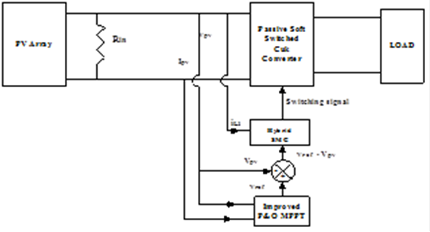
A passive lossless soft switched Cuk converter is designed for reduction of output ripple current, reduce switch voltage stress, to boost power level and improve efficiency of PV system. In order to minimize the number of components and design cost, a soft switched Cuk converter with a single capacitor turn-off snubber for PV applications is proposed. The proposed Cuk converter experiences minimum voltage stress on switch and thus losses are minimized. P&O MPPT algorithm is used for swift and maximum extraction of power from PV module with changes in solar radiation and temperature. Implementation of optimum MPPT tracker increases the life time of PV system Figure 1 shows the proposed block diagram.
2.1 Modified Cuk converter topology
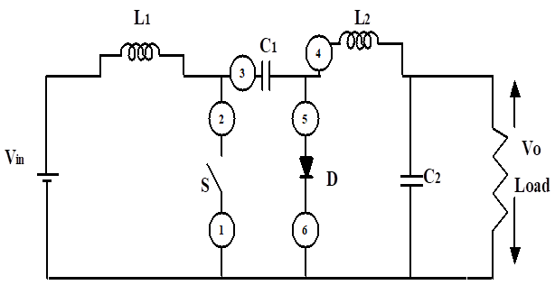
The schematic of a conventional non-isolated Cuk converter with two inductors L1and L2, Capacitors C1, C2, a MOSFET(active switch ) Sand a diode D is shown in Figure 2.
The advantage of Cuk converter over buck,boost and buck boost converters is the input and output inductors result in a filtered current on both input and output sides. Therefore ripple current is minimized improving efficiency. But the problem with PV array is its non linear nature. Conventional hard switched Cuk converter will not be able to produce maximum efficiency and track power because of voltage stress and switching loss experienced by switches.
During a single switching cycle switches realize stress because of current and voltage overlap losses. Passive soft switching is better compared to active switching as it do not require an extra switch. Design methodology for a new passive lossless non-inverting Cuk converter with single active switch is described here. The same steps can be followed for evolving circuit with more than one active switch.
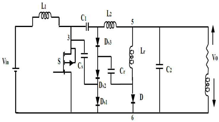
In a circuit with only one active switch one Zero current Inductor(ZCL) and Zero Voltage Capacitor(ZVC) is enough to provide zero-current turn on and zero-voltage turn off of the active switch . The locations of the turn-on inductor L r and the turn-off capacitor C r are depicted in Figure 3. Additional lossless passive components are to be added for recovery of energy from the ZCL and ZVC. Any number of additional components can be interconnected.
The procedure to design a modified converter topology is as follows.
First step is location of ZCL. Number of ZCL (Lr) placed is same as number of active switching PWM converters. Switch voltage produced in the loop drops after inserting resonant inductance Lr. There are six possible locations for Lr to achieve zero current turn on MOSFET switch .An optimum point with minimum voltage stress is chosen as diode branch location number 5 shown in Figure 3.
The inductor Lr in series with diode must be charged when switch S turns off. Therefore to make the circuit lossless an alternate path is to be provided to reduce voltage spikes and the control of charging and discharging of ZCL energy. A voltage storing device (VSD), capacitor acts as a stiff voltage device by acquiring energy from ZCL for every switching cycle. In PWM converters like buck, Zeta, Cuk a filter capacitor is used which transfers energy to load resistor. Now the work of VSD is to transfer energy to inductor when active switch diode is conducting. The inductor transfers energy to source or load when diode turns off. There are nearly 6 possible locations of capacitors as shown in Table 1 and Cr is optimally located shown in Figure 4.
The passive components Cr, Cs and Ds form the snubber circuit as shown in Figure 4.Using concept of graph theory ZVC sub circuit is taken from hard switched topology.ZVC must reset when active switch turns on.
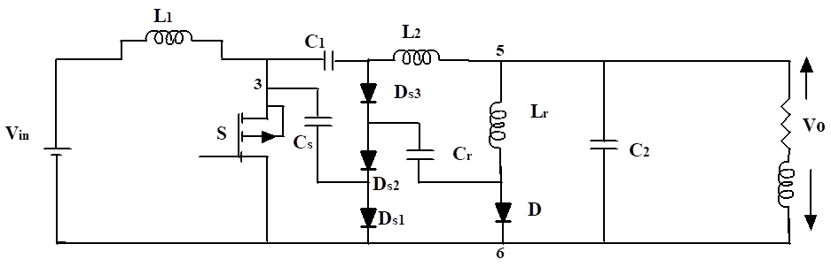
Using the above steps the passive lossless CUK converter topology is designed and shown in Figure 4. In Figure 4 Lr and Cr are the ZCL and ZVC. Ds3 and Cr make up the ZVC sub circuit. Lr also transfers the energy in Cr to Cs. Cs recovers the energy in Lr and Cr Diodes Ds1, Ds2, Ds3 transfer the energy in Csto the load or energy transfer capacitor each switching period A snubber circuit cell shown satisfies the pertinent turn-on and turn-off snubber properties but do not maintain the minimum voltage stress across the switch.
For these cells C s is a relatively large capacitor and stores the inductor and capacitor energy.
The operation of the Cuk converter with the snubber cell shown in Figure 5 is considered. Assumptions made for circuit analysis are:
MOSFET switch and the passive components are ideal.
The transients of active switch turning on and off are small and the converter filter inductor currents remain constant at their values when the turn on and turn off transients are initiated.
-
The converter input and output voltages and other filter capacitor voltages are ripple free.
The operating stages of the passive lossless soft switched PWM Cuk converters during a switching cycle can be divided into 9 stages
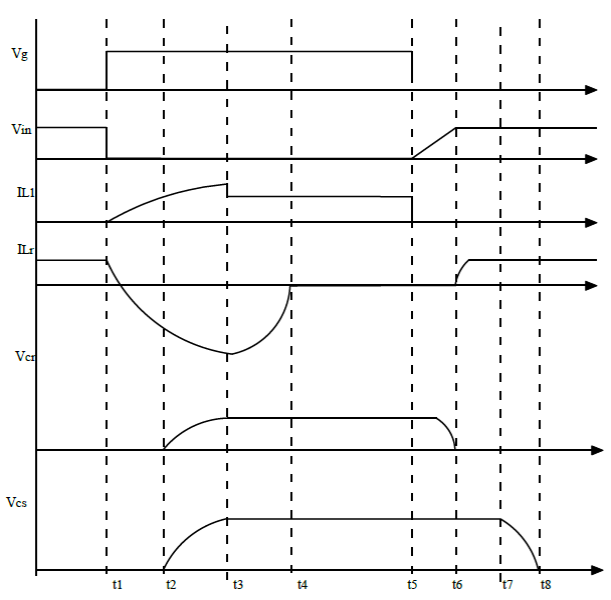
Mode 0: Cuk converter MOSFET turn off time to < t <tl
The off time of the MOSFET is selected here as the first stage of the switching cycle. In this interval, to< t < t1 the inductor filter current or the sum of the inductor filter currents flows through a series combination of the snubber inductor Lr and the free wheeling diode D1. The current through diode branch 56 falls from I2 at t = t0 to I1 at t = tl .Now Vcr = V31 and snubber capacitor voltage Vcs =0.
MOSFET turn on transient (t1 <t< t4)
Mode 1 : tl < t < t2: Here MOSFET is turned on at t = tl and this places a voltage across Lr positioned in series with D between terminal 5 and 6. This voltage turns off the free wheeling diode D at zero current and zero voltage at t = t2.By the end of stage 1 switch current becomes I1
Mode 2: t2 < t < t3: At t = t2, resonant mode occurs and a resonant current flows in the loop Ds2 Cr Lr53 of the circuit cell. Diode Ds3 becomes forward biased at t = t3 and starts conducting current. Hence, voltage across Cr is clamped to V31s.This marks the end of this stage.
Mode 3: t3 ≤t ≤t4: During this interval diodes Ds3 and Ds2 is forward biased and the resonant inductor current oscillates in the loop made of Ds3, Ds2, Cs and Lr until the resonant inductor current becomes zero at t = t4.
Mode 4: MOSFET on time t4 ≤t ≤t5: In this interval, MOSFET switch S carries the filter inductor current. The switch current rises from I1 at t = t4 to I2 at t = t5.
MOSFET turn off transient interval: t5 ≤t ≤t9
The transient associated with MOSFET turn off has four stages described as follows:
Mode 5: t5 ≤t ≤t6: MOSFET switch S is opened at t = t5 and the entire switch current I2 is diverted to charge the buffer capacitor Cr through diode Ds3.This charging action makes the switch voltage to rise from zero (at t = t5) at a rate that ensures zero voltage turn off of the switch. The stage ends when diode Ds2 (with Ds3 already conducting) becomes forward biased and starts to conduct at t = t6.
Mode 6: t6 ≤t ≤t7: In this sub stage, the current I2 flowing in and out of the cell circuit splits into two parallel paths, one consisting of Ds3 in series with Cr and the other with Lr ,Cr, Ds1 and Vo in series . Substage42 ends at t = t7 when Ds2 becomes forward biased so that the conduction of all the three snubber diodes clamps Vcr to V12.
Mode 7: t7 ≤t ≤t8: In this stage, the snubber diodes Ds2 and Ds1 conduct and the resonant inductor current rises from its value at t = t7 to I2 at t = t8.
Mode 8: t8 ≤t ≤t0: In this stage, all snubber diodes stop conducting and the current I2 charges the capacitor Cr and this charging continues until Vcs is decreased from its value at t = t8 to zero at t = t0 At t = t0, the freewheeling diode D becomes forward biased and the current I2 is instantaneously transferred to it at zero voltage.
The nine stages of operation of converter is shown in Figure 5. The minimum voltage stress of 60 V produced in MOSFET switch S is shown in Figure 6. It can be seen from Figure 6 that the noise at the switching frequency of the proposed converter is approximately 70 db.
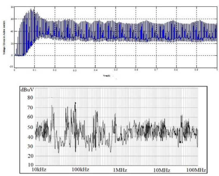
An important advantage of this new topology is continuous current at both the input and the output of the converter with reduced stress on MOSFET switch. In spite of high number of reactive components the proposed converter improves the conversion efficiency of the system. With such a minimum voltage and current stress on the switch the converter has wide scope in various industrial applications. Therefore the proposed converter is applied in the PV system discussed in this paper.
2.2 PV system configuration
The mathematical model of the PV panel is briefly described below. The model of PV cell shown in Figure 7 consists of a diode representing the PN junction diffusion current. Two resistors (series and shunt) are added for the losses. The unknown parameters of the models are functions of the incident solar irradiation and panel temperature.
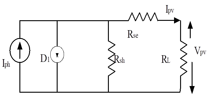
The PV cell is mathematically represented as,
where Ipv ,Vpv denote PV cell output current and voltage. Io is dark saturation current, Rse, Rsh is series and shunt resistance and VT is thermal voltage
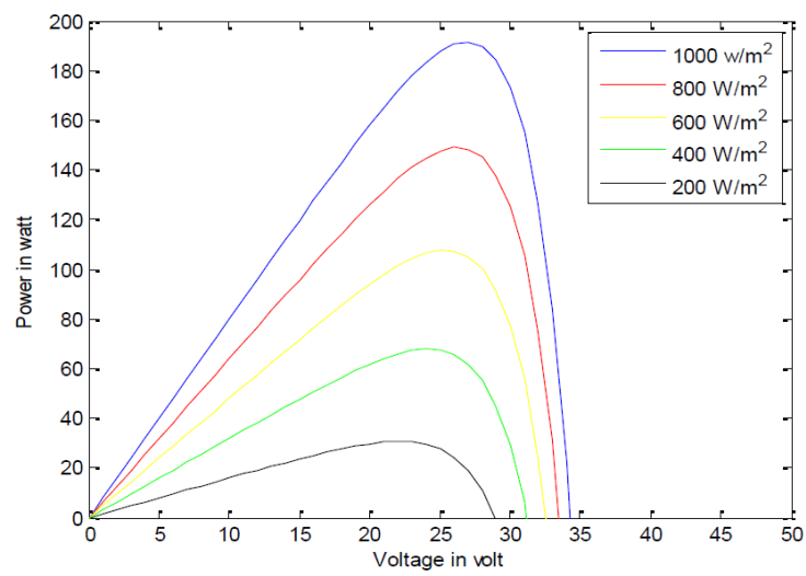
Figure 8 shows the Current - Voltage and Power-Voltage characteristic curve of the PV array for various ranges of irradiances at a constant PV array temperature (25°C). The characteristics of PV array depend on two factors, irradiation and the temperature. Therefore, a new algorithm based on hybrid SMC is proposed to continuously track MPP ensuring that the PV system achieves stable maximum output power quickly.
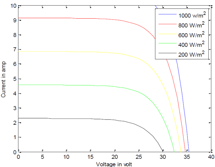
A PV array with 18 PV cells connected in series and parallel arrangement is simulated in MATLAB and results are discussed in this section. Individual PV cell has an open circuit voltage Voc= 0.9 V and short circuit current Isc = 0.63 A solar panel is formed from the combination of such modules.
A solar array is formed with maximum power of 39.2 w at Vpv=25.2 V and Ipv=9.1 A. At a predefined irradiance condition of 1000W/m2 the PV cell produces MPP which can be observed from PV cell characteristics shown in Figure 8 and Figure 9.
3. Design of hybrid SMC
Non linear control techniques are suitable for improving the efficiency of MPPT controller. SM control exploits the Variable Structure Systems (VSS) nature of higher order converters, here Cuk converter. The objective of implementing SMC is to extract maximum power from the PV source and reject the disturbances (load fluctuations) occurring at the converter output.
A hybrid Digital SM based MPPT controller design is discussed in this section. The modeling of PV source is based on Norton’s equivalent circuit, where the parameter Rin is the differential resistance of the source and current Ipv depends on the irradiance level and on the PV output voltage.
The two steps in SM control are:
P&O MPPT technique is discussed in the following subsection to design discontinuous control law.
3.1 Improved P&O MPPT controller
In this paper design of discontinuous control law is based on Improved P&O technique. The PV array has nonlinear characteristics. So MPP is tracked using an iterative technique, Improved P&O that involves PV voltage and current. The Cuk converter interfacing the PV array is fourth order system consisting of L and C components. Therefore in the proposed system, the MPPT unit uses the Hybrid SMC to generate control signal. The sliding mode regulates a linear combination of the PV voltage and current in a very rapid manner. MPPT is used to calculate the equivalent control signal to obtain the maximum output voltage.
The steps in Improved P& O method shown in Figure 10 are:
During perturbation K suppose that, the solar irradiation is increased under fixed load RL. MPP moves from a lower point to upper point in the I-V curve. Hence voltage perturbation increases.
Both increasing of PV power and voltage under constant load from lower to upper I-V and P-V curves will give positive change in power ΔP > 0 where ΔP = P(K) − P(K − 1) and positive change in voltage ΔV > 0 , ΔV = V(K) − V(K−1)without change in load resistance. Both positive change in power (ΔP > 0) and voltage (ΔV> 0) under constant load (ΔRL=0) will orient algorithm to decrement voltage perturbation to obtain new MPP.
If solar irradiation is decreased from next instant of perturbation K+1 of P&O algorithm, voltage level reduces and move the MPP from upper I-V curve to MPP on lower I-V curve . The transferring of operating point will also decrease the PV power under fixed load with negative change in power ΔP < 0 , and negative change in voltage ΔV < 0 . Both negative change in power negative change in power (ΔP < 0) and voltage (ΔV< 0) under constant load (ΔRL=0) will orient algorithm to increment voltage perturbation to reach MPP.
When the load is varied under constant weather conditions, the conventional P&O algorithm will track MPP of PV system with best performance.
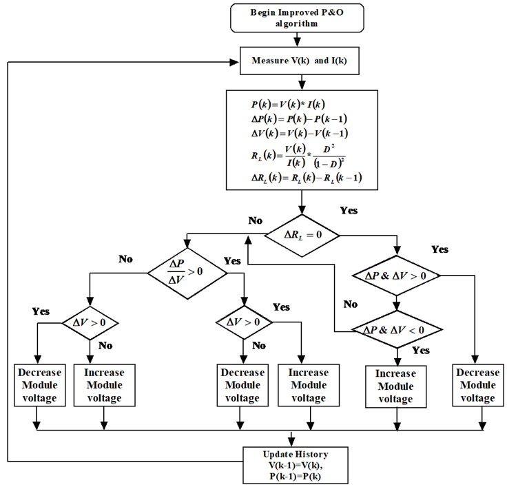
In this method voltage is sensed and output power is checked by varying the supply voltage .Duty ratio increases with increase in voltage and power. Duty ratio decreases with decrease in voltage and power. These steps continue till maximum power is reached. Thus the voltage at which MPP is reached is tracked. The voltage produced is fed as control signal vref to the HSM controller.
3.2 HSM control of modified Cuk converter
An important advantage of the proposed passive lossless Cuk converter topology is a continuous current at both the input and the output of the converter with reduced stress on MOSFET switch at output. In spite of high number of reactive components the proposed converter improves the conversion efficiency of the PV system.
The proposed HSM based MPPT technique is applied to the Cuk topology shown in Figure 4. The output of converter is assumed to be constant voltage source as in the case of battery chargers. The SM controller for Cuk converter is modeled by state space representation methodology.
Sliding surface for higher order converters can be defined as
where N is order of converter. Here cuk converter is fourth order converter. It is known that the converter dynamics is represented by
The procedure in (Sira-Ramirez, 1987) is followed to calculate A, B, C and D. For the analysis let us assume the system variables to be,
The differential equations for the Cuk converter during on state of control signal , u=1 is
The differential equations for the Cuk converter during off state u=0 is
The sliding surface S for the proposed system is represented by
where vref is control signal for SM controller derived from MPPT controller, iref is current loop reference (PV system is modeled as current source ), signals iL1 and vpv are obtained from the cuk converter .
The condition for driving the MOSFET S :
when u=1, S goes to ON state and u=0, S goes to OFF state. The system variables for the converter are,
The matrices A, B, C, D are calculated from the differential Equation (5).
From the above matrix representation it is inferred that derivative of IL1 affects control signal u fed to MOSFET switch S. For Digital representation of above signal the hybrid SM Equation (7) can be represented as
where vref, the output of MPPT controller can be represented as a digital and Tc is the sampling period. The additional signal H is introduced in order to have an hysteresis band around the ideal condition: u is the signal at the output of SM controller which is used as modulating signal for driving the switches The additional signal H/2 is used to modulate the hysteresis band H, whose amplitude defines the switching frequency.
The above version of (7) makes digital implementation simple. Using Eulers backward transformation (10) is transformed into digital form.(11)
The above transformations (11) aids in conversion of analog form of SM (7) into a hybrid representation (12).
The hardware implementation of the hybrid SM system is done using PIC 16F877A equipped with two fast analog comparators The memory size, the computational capability and the ADC performances are also suitable for implementing the MPPT algorithm, the digital part of the SM control and some additional routines for monitoring and safety protection.
4. Results and discussions
The dynamic response of the hybrid SM MPPT controller for modified Cuk converter is obtained by MATLAB/Simulink software. The specifications for simulation is shown in Table 2. The response of PV voltage does not depend on differential input resistance of the PV source and parameters of DC-DC converter , but depends on SM gains. Simulation results are shown for variations of reference voltage and irradiation level.
Table 2. PV panel and Cuk converter specification.
| Description | Parameter | Nominal Value |
|---|---|---|
| PV panel specification | ||
| Maximum Power | Pmax | 85.2 W |
| Short circuit current | Isc | 5.45 A |
| Voltage at MPP | Vmpp | 28.4V |
| Current at MPP | Impp | 9.1A |
| Open circuit voltage | Voc | 22.2 V |
| Solar irradiance | 1000 W/m2 | |
| Ambient temperature ◦ | T | 25°C |
| Cuk converter | ||
| Primary Inductor | L1 | 15µH |
| Primary Capacitor | C1 | 22 µF |
| Secondary Inductor | L2 | 15 µH |
| Secondary Capcitor | C2 | 44 µF |
4.1 Simulation results
PV system with HSM Contoller has been designed and simulations were performed on a Cuk converter circuit with specifications given in Table 2. The performance analysis of the proposed system is done for the following.
The above mentioned analysis is done for various irradiation changes.
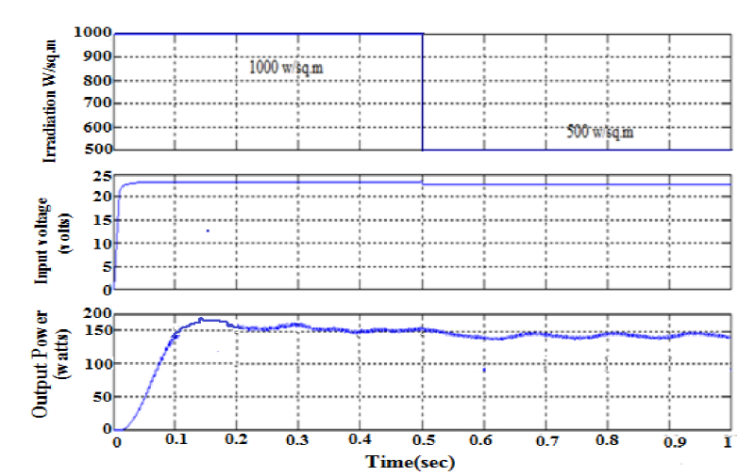
The simulation results for Conventional Cuk Converter with hybrid SM control is shown in Figure 11. A peak overshoot of 160 W is produced in 150 ms. After 200 ms output power is stabilised to 154 W and system converges after 350 ms to 150 W.
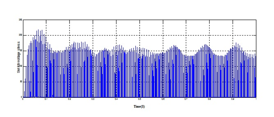
The change in switch voltage stress is from 200 V at 50 ms to 175 V at 200 ms is shown in Figure 12. Because of such a heavy voltage stress more losses are produced.
The efficiency of PV system with conventional Cuk converter is poor. The output power profile as shown in Figure 13 varies from a peak of 168 W at 40ms to 160 W at 140 ms. Compared to conventional Cuk converter the system settles and converges faster in 160ms.
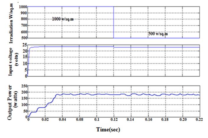
Figure 14 illustrates switch voltage stress over switch S. The voltage stress is reduced to 65 V and is maintained constant throughout the switching cycle. As a result of such a reduced stress peak power is improved, losses are minimized and efficiency of the system is improved to 98.8%.The results are tabulated in Table 3.
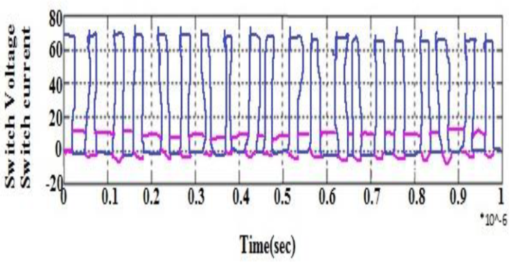
Table 3. Efficiency Comparison for different Irradiation.
| Methodology | Step Irradiation 500 W/m 2 to 1000 W/m 2 | Constant Irradiation 1000 W/m 2 | Efficiency % | ||
|---|---|---|---|---|---|
| Output Power Profile (W) | Tracking time (ms) | Output Power Profile (W) | Tracking time (ms) | ||
| Cuk with HSM MPPT Controller | 154 to 160 W | 350 | 160 W | 300 | 90.2 |
| Modified Cuk with HSM MPPT Controller | 160 W to 168 W | 35 | 168 | 40 | 98.8 |
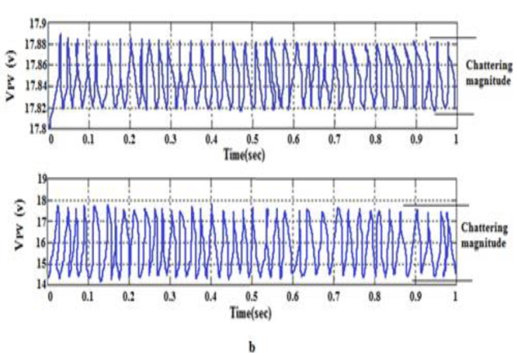
Figure 15 compares the PV voltage chattering in Hybrid SM MPPT controller and PWM controller. It can be seen that the HSM MPPT has less chattering of 60 mV as shown in Figure 15a.Here the PV voltage oscillates between 17.8 and 17.88 V. In PWM controller (figure b) PV voltage oscillates between 14.5 and 17.9 with a chattering of 3.9 V at higher switching frequencies.. The high frequency chattering during the variable weather condition has been maintained with in a limit 60 mV in case of HSM based MPPT controller.Hence tracking time is reduced to 40 ms. Hence because of controller gains tracking time is improves and fast response is obtained in case of Hybrid SM MPPT controller.
4.2 Experimental validation
Figure 16 shows the laboratory prototype of converter integrated with controller that is used for procuring experimental results. The hardware implementation of hybrid SM controller is done by using PIC 16F877A microcontroller. Opto coupler used in the gate drive circuit to amplify and translate the pulse signal is HCPL 2232. Programming has been carried out in Embedded C (Mirco C Compiler). The Power MOSFET of the proposed system is IRFP460. The diodes used in snubber cell areMUR3060.The experimental validation of simulations results are shown in Figure 17 and 18.
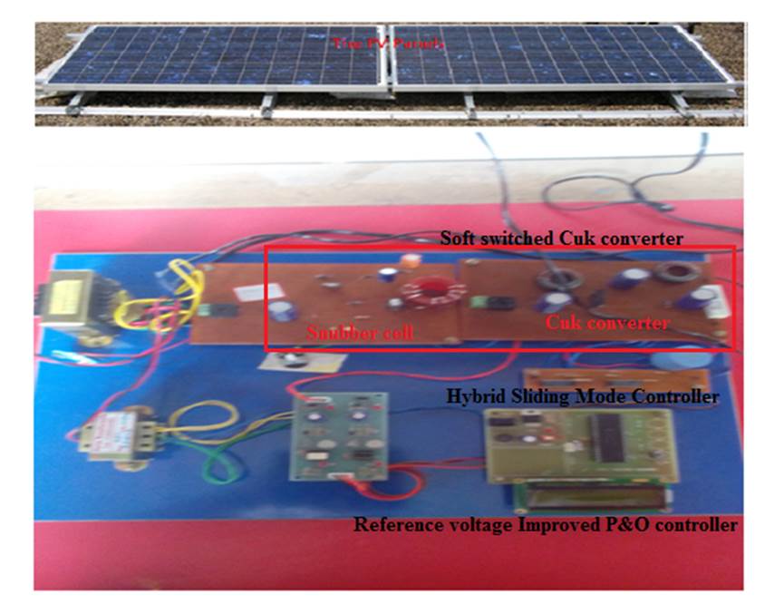
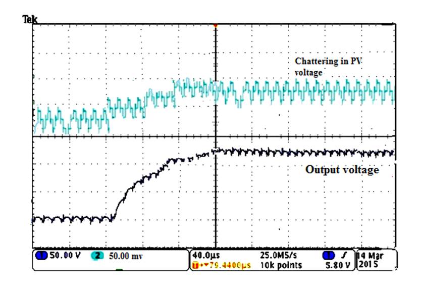
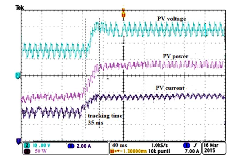
Figure 17 shows the chattering effect in PV voltage and output voltage of proposed Cuk converter. The PV voltage maintains a reduced chattering of 60 mv. It can also be seen that for a step variation of solar irradiance from 500 W/m2 to 1000 W/m2 at 0.5 s, the output voltage is maintained constant at 85 V with a tracking time of 35 ms. Therefore, it is clear from the above results that the HSM MPPT performs efficiently performing for both MPPT and output voltage regulations.
In hybrid SMC based MPPT, with optimal switching surface a sudden step in input radiation is produced by introducing a change in irradiation from 500 W/m2 to 1000 W/m2 and step response is shown in Figure 18. The MPPT algorithm step size is 0.2 for the HSM-MPPT and 0.02 for IPO- MPPT. The step time chosen for both controllers is 30 ms per step. The HSM MPPT is seen to converge within 35 ms.
The MPP from the PV panel and the power output of the Cuk converter under varying irradiance conditions were analyzed. From this, it can be concluded that under dynamic irradiance condition HSM Controller tracks the MPP faster in 35 ms and achieves maximum power of 168 W.
The efficiency of Cuk converter is enhanced to 94.2% because of and makes it a suitable choice for solar applications. With such a minimum voltage and current stress on the switch, the converter power tracking efficiency is improved to 98.8%. The proposed converter with Hybrid SMC can be implemented in battery charging, driving motors, Photovoltaic pumping machines in agricultural sector, Military applications etc.
5. Conclusion
HSM based MPPT controller has been implemented using a passive lossless Cuk converter. Design steps for the modified Cuk converter is proposed. The proposed converter with snubber cell reduces voltage stress of active switch at turn on and off to V. Therefore conversion efficiency of the Cuk converter is improved to 94.2 % and hence PV system power conversion efficiency is enhanced to 98.8%. Further the sliding mode gains are chosen in such a way that chattering is reduced to 60 mV and tracking time is improved to 35 ms. It is clear from simulation results that the passive soft switched non inverting Cuk converter with HSM controller has minimum ripple, reduced switch voltage stress and conduction losses with increase in efficiency.Results are validated by simulation and experimental results.

