


 nueva página del texto (beta)
 Inglés (pdf)
 Artículo en XML
 Referencias del artículo
 Enviar artículo por email
 Citado por SciELO
  Similares en
SciELO
Similares en
SciELO 
 Permalink
1. Introduction
Nowadays, DFIG is very popular WT generators due to its high energy conversion efficiency, decoupled power (active and reactive) controls and use of partially rated B2BC converter (Chowdhury & Chellapilla, 2006). The B2BC consists of two converters: (i) Rotor Side Converter (RSC) and (ii) Grid Side Converter (GSC) and both the converters are connected together through a common DC-link capacitor. The objective of GSC is to maintain the constant DC-link voltage across common capacitor irrespective of the active power flow of rotor, and RSC is used to achieve variable speed operation by injecting the controllable rotor voltage into the rotor windings of DFIG (Datta, Mishra, & Roy, 2016).
Furthermore, reduction of cost and minimization of losses are main concern of many applications, and, thus, the number of semiconductor switch reduction and improvements through topological modification of the converter should be one of the major considerations. Cardenas et al. (2009) and Nikkhajoei and Lasseter (2008) has been proposed a matrix converter (MC), consists of nine bi-directional switches without DC link capacitor, based DFIG-WT system. However, the switching strategies based on classical PWM cannot be applicable for this type of MC due to the limitation of switching frequency and requirement of additional auxiliary clamp circuit (Klumpner & Blaabjerg, 2002). The functionality of a conventional MC could be realized by 18 switches based direct or indirect MC. It has six more switches than B2BC, but has the benefit of compactness and lifespan extension due to deletion of the common DC-link capacitor. The indirect sparse MCs, consists of nine power switches, proposed by Kolar, Schafmeister, Round, and Ertl (2007) and Loh, Blaabjerg, Gao, Baby, and Tan (2008), but it supports only unidirectional power flow. If variable speed and constant frequency (VSCF) operation and specified direction of power flow are main requirement, then MCs are not suitable choice.
Blaabjerg, Freysson, Hansen, and Hansen (1997) has been proposed another power converter topology, known as B4 converter for conversion of energy. Two B4 converters, consists of total eight numbers of switches, are required for dual AC drive systems which perhaps is the least possible for interfacing dual AC drive systems (Ledezma, McGrath, Muñoz, & Lipo, 2001). The resulting form of power converter must then be more technically referred to as the B8 power converter and it suffers from large voltage variation across DC-link capacitor. Five-leg converter has been proposed, by Jone, Vukosavic, Dujic, Levi, and Wright (2008) and Su and Hsu (2006), for rectifying drawbacks associated with B8 converter. But, it is unsuitable for variable speed drives applications because of the infliction of common frequency operation on the dual connected AC motor drive systems.
Recently, the NSC has been found as a competitive substitute to the existing B2BCs that employs twelve power electronics switches (Datta, Mishra, & Roy, 2018; Kominami & Fujimoto, 2007a; 2007b; Lui, Wu, Zargari, & Xu, 2007). It reduces the number of component count, switching losses, installation area, cost of the system, and increase system efficiency. NSC has previously been validated experimentally in both fixed and different frequencies based dual machine drives system and also explained the possibility of using it in place of the B2BC (Kominami & Fujimoto, 2007a; 2007b; Lui et al., 2007). Gao et al. (2010), Lei, Loh, and Gao (2012), Liu, Wang, Loh, and Blaabjerg (2011) and Ojo (2004) have been introduced various forms of modulation techniques for NSC, for achieving both constant frequency (CF) and different frequency (DF) modes of operation. In this paper, DFIG-WT system with NSC and its control scheme, shown in Fig. 1 and Fig. 2 respectively, are presented to achieve VSCF operation of a grid connected system under varying wind velocity. For this, a simulation model of a 1.5 MW DFIG based WT system is implemented in MATLAB/Simulink platform. The paper is organized as follows: Section 2 and 3 presents, NSC based DFIG-WT system and speed sensor based control scheme respectively. Simulation results are shown in section 4. Finally, conclusions are drawn in section 5.


2. Proposed NSC based DFIG-WT system
2.1 Description of the Study System
The diagram of the DFIG-WT system equipped with NSC is shown in Fig. 1. Similar to B2BC based GSC and RSC, the upper three output terminals of NSC are connected to the rotor windings of the DFIG via slip-rings and brushes to deal with rotor power at variable frequency and other three output terminals of NSC (i.e. lower output terminals of NSC) are joined to the grid for realizing the exchange of power between rotor and grid at UPF.
Speed sensor based vector control technique is proposed for extracting the maximum power for wind speed up to the rated range, but pitch angle control mechanism is introduced while velocity of wind crosses its rated limit to restrict the captured wind power within the rated capacity of the turbine and thereby to avoid overloading and outage. The detailed mathematical modeling of wind turbine, DFIG, MPPT algorithm and blade pitch angle controller are well discussed by Datta et al. (2016) and those are used in this study as well.
2.2 Nine switch converter
Fig. 1 shows the NSC based DFIG-WT configuration. It has 3-layers of IGBTs: upper-layer (U-layer, comprising of power switches S1, S4 and S7, one for each of 3-phases); lower layer (L-layer, with power switches S3, S6 and S9); and middle layer (M-layer, with power switches S2, S5 and S8). Individual power switches of all three layers are joined in series to form three legs for three phases and their parallel combination is placed between 0 (lower rail, N) and +Vdc (upper rail, P). M-layer switches in conjunction with appropriate switch in U- and L-layer provide rectifier operation, convert AC power received from grid into DC and deliver to P and N rails (e.g., when S1 is connected to P-rail and S5+S6 is connected to N-rail, AC power is inputted to PN-rail through “ar”-“br” phase). Simultaneously, if S3 is connected to N-rail and S7+S8 is connected to P-rail then power from DC-rail goes to the output terminals “gcc”-“gca”. Thus, both the modes of operation run simultaneously by sharing the switches in the middle layer. As the switches in middle layer is shared for bi-directional operation, the number of switches required reduces from 12 to 9 thereby decreasing the component count by 50% and 33% in comparison to the 18-switch based conventional MC, and 12-switch based B2BC respectively (Liu, Wu, Zargari, Xu, & Wang, 2009). The combination where U-switch of a phase needs to be connected to P-rail, for one mode of operation, and simultaneously, L-switch of that phase need to be connected to N-rail through M-switch, for other mode of operation, is not achievable as this short circuit the DC-rails. This constitutes a limitation for the NSC. The constraint is taken care of while generating trigger pulse and is obtained by keeping the modulating reference signal for the lower terminal of NSC below that of the upper terminal of NSC (Liu et al., 2009; Kominami & Fujimoto, 2007a). The triggering pulses, for both the upper and lower terminals of the NSC, are generated by comparing the carrier signal with their respective modulating references. The logical XOR operation is used to generate the triggering pulses for middle switches of the NSC.
2.3 Modulation scheme for NSC
For NSC, the output controlled voltage is achieved by the use of IGBT based switches on each leg (Liu et al., 2009). Because, the switches of m-layer are shared by both inverter and converter operation, it can also be noticed that one switching state of 12-switch B2B converter does not exist in NSC. This implies that the converter leg voltage (VgcaN) output for lower terminal (phase-a) of NSC must not be higher than leg voltage (VarN) output for upper terminal (phase-a) of NSC, at any instant and is the key limitation for the NSC. This is not a severe drawback, since power electronics conversion topologies would have very much diluted the spectral gains introduced anyhow (Lei et al., 2012). Being unrealizable and unimportant, the aim set for modulating the NSC must not be the spectral gain, but rather reduction in switching losses. With later aim in mind, the instant modulation choices for consideration would likely be from the conventional discontinuous schemes, like the 60◦ and 30◦ discontinuous schemes, proposed by Ojo (2004). These schemes (60˚ and 30˚discontinuous) are found to be not appropriate for NSC (Zhang, Loh, & Gao, 2012), since they require dc-rail clamping per set of output terminals of NSC and sometime cause upper reference signal to fall below lower reference signal, which technically cannot be met by the NSC. NSC allows only upper dc-rail clamping for its upper terminal phases and lower dc-rail clamping for its lower terminal phases, which can only be fulfilled by 120˚ discontinuous modulation scheme. 120˚ discontinuous modulation schemes for both CF and DF modes are described in details by Zhang et al. (2012), Liu, et al. (2011) and Ojo (2004). DF mode based 120˚ discontinuous modulation scheme is presented in this paper, as this mode is only the key concerned of this paper.
2.4 DF mode (Datta, Mishra, & Roy, 2015)
DF mode corresponds to the setting of different frequencies for the two set of terminals of NSC to which either sources or loads are connected. It is required for operating NSC at DF in WT system, where the RSC and GSC frequencies are different. To begin this mode, the two set of Equations (1) and (2) are needed to generate modulating references at different angular frequencies (ωr ≠ ωg, where, ωr= angular frequency for rotor and ωg= angular frequency for grid).
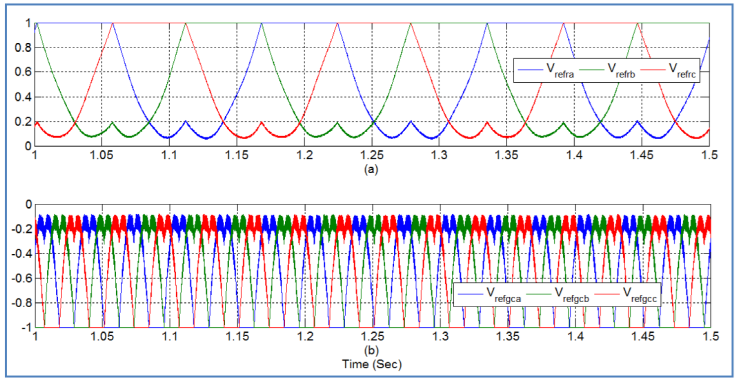
For avoiding crossover of modulating references in case of addition of proper triplen offsets, their magnitudes should satisfy Mr + Mg ≤ 1 or 1.15. The generations of switching sequence and placement of reference-carriers under this condition are presented in details by Gao et al. (2010). It is discussed in the survey that a superior aim set for the DF mode is to choose an appropriate discontinuous modulation scheme to shift the reference modulating signals to get some advantages for loss minimization through proper DC-rail clamping. Fig. 3 shows the modulating references for lower and upper converter at different frequencies, obtained by using Equation (3). It can be observed, from Fig. 3, that modulation references signals, for upper and lower terminals of NSC, do not intersect with each other.
3. Speed sensor based vector-control technique for NSC
The detailed schematic of proposed control technique for NSC based RSC-GSC is shown in Fig. 2. The NSC faces restrictions imposed on its permissible switching signal states like most of the reduced converter topologies. The NSC output terminals per phase can only be joined to either 0 V [for ‘b’ phase: S4-OFF, S5-ON, and S6-ON] or +Vdc [for ‘b’ phase: S4-ON, S5-ON, and S6-OFF] i.e. the upper and lower output terminals are connected to +Vdc and 0 V respectively [for ‘b’ phase: S4-ON, S5-OFF, and S6-ON]. But, the switching combination where the upper and lower output terminals require to be joined to 0 V and +Vdc respectively is not permitted [for ‘b’ phase: S4-ON, S5-ON, and S6-ON] as this short-circuits the DC-link capacitor. Two modulating reference signals, without intersecting each other, can be used to resolve that limitation (Liu et al., 2009). In order to accomplish this, one modulating reference signal must always be kept above that of other reference signal by including DC-offsets voltage signals with both the modulating reference signals. 1200-discontinuous modulation based modulating reference signal adjustment techniques for NSC is derived by Lei et al. (2012). The modified modulating reference voltage signals for upper and lower switches of the NSC can be computed using Equation (4).
The reference controlled voltage signal (V* gcabc), as shown in Fig. 2, is produced by vector control method based on grid-voltage, using mathematical equations presented by Datta et al. (2016), in order to control NSC for achieving decoupled control of : (i) active power flow between DC-link capacitor of NSC and grid (using d-axis component of current (iabcg) flowing between lower terminals of NSC and grid, to regulate DC-link voltage Vdc at its constant value) and (ii) reactive power flow between grid and lower terminals of NSC (using q-axis component of current (iabcg)). The active power, flows between NSC and grid, and hence the voltage across DC-link capacitor is directly proportional to idg, and can be controlled by regulating Vdgc* while, the reactive power, flows between NSC and grid, is directly proportional to iqg and can be controlled by regulating Vqgc*. In operation at normal mode, the reference d-axis current component idg* is produced by regulating DC-link voltage based PI controller and the reference q-axis current component iqg* is chosen zero for achieving unity displacement factor operation. The detailed mathematical modelling of GSC is discussed by Datta et al. (2015).
The reference controlled rotor voltage (V* abcr) is generated by using field oriented control (FOC) approach, using equations presented by Pena, Clear, and Asher (1996), to control rotor current to achieve its desire value. In this section, speed sensor based stator field flux oriented vector control method is used and designed in synchronously rotating reference (dq-axis) frame, with d-axis oriented along with stator-flux vector position, for controlling the active power flow between DFIG (stator and rotor) and grid via NSC for tracking the MPP of the WT. The rotor position and speed are sensed from DFIG to transform rotor current components from one frame to another frame i.e. rotor rotating reference frame to synchronously rotating reference frame and vice verse and also to compensate back emf component of the rotor current controllers. The mathematical modelling of speed sensor based stator FOC approach is reported by Pena et al. (1996). The PWM voltage source converter is current controlled with the d-axis component of rotor current used to control the reactive power flow of stator and q-axis component of rotor current used to control the active power flow of stator. The active and reactive powers flow of stator are directly proportional to iqr and idr respectively and can be controlled by controlling Vqr* and Vdr*. The reference qd-axis rotor currents (iqr* and idr*) are generated by using active and reactive power PI controllers.
The three phase controller reference signals (V*’ abcr and V*’ gcabc) are applied to PWM generators for generating the two dissimilar sets of six triggering pulses. If the RSC-GSC based B2BC operations are to be accomplished, the pulses generated by PWM generators can be directly fed to the corresponding converters. Nevertheless, in a NSC, the triggering pulses for M-layer switches are produced by logical EX-OR operation of PWM triggering signals corresponding to lower three triggering pulses (2, 4, 6) generated by PWM-I and lower three triggering pulses (2, 4, 6) generated by PWM-II as shown in Fig. 2. It is also shown in Fig. 2 that the PWM triggering signals corresponding to the upper three switching pulses (1, 3, 5) generated by PWM-I and upper three switching pulses (1, 3, 5) generated by PWM-II are fed to U-layer and L-layer switches, respectively, of the NSC.
4. Simulation results and analysis of the system performance
An extensive simulation study is done by developing the model of the NSC-based DFIG-WT system in MATLAB/simulink platform. Results of the proposed control scheme are validated in simulink level while achieving VSCF operation under varying wind velocity. The time responses of the system (NSC-based DFIG-WT) outputs are obtained with proposed control scheme (Fig. 2) to study the performance of the system. All relevant parameters of the study system are given in the Appendix (Pokharel, 2011).
In this section, responses (both steady state and transient) of the study system have been obtained when the system is subjected to a set of wind velocity, as indicated in Table 1. The time responses of : (i) pattern of wind velocity (Vw); (ii) reference and actual speed of rotor (wr* and wr); (iii) co-efficient of power (Cp); (iv) reference and measure active power of stator (Ps* and Ps) (v) mechanical and electro-magnetic torques (Tm and Te); (vi) reference and actual stator reactive powers (Qs* and Qs); (vii) dq-axis stator voltages (Vds and Vqs); (viii) dq-axis rotor currents (idr and iqr); (ix) rotor power (Pr); (x) waveform of rotor current; (xi) rotor voltage (Vr); (xii) reference and actual DC-link voltage (Vdc* and Vdc); (xiii) dq-axis current between GSC and Grid (idg and iqg); (xiv) Grid reactive power (Qg); and (xv) Blade pitch angle (β), are presented in Figs. 4.

Fig. 4. (a) Wind Velocity (Vw), (b) Reference and Measured Generator Rotor Speed (ωr* and ωr), and (c) Power Co-efficient (Cp).
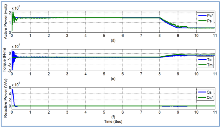
Fig. 4. (d) Reference and Actual Stator Active Power (Ps* and Ps), (e) Mechanical and Electro-magnetic Torque (Tm and Te), (f) Reference and Actual Stator Reactive Power (Qs*and Qs).
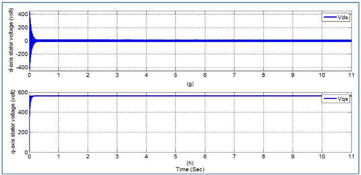


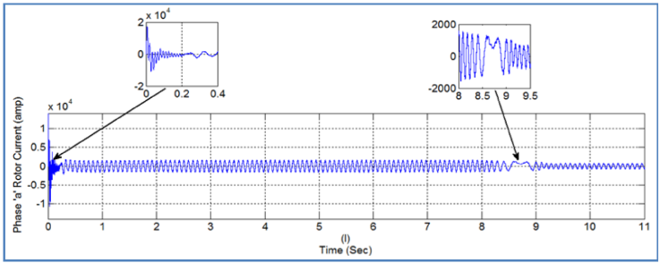


Fig. 4. (o) d-axis Current between GSC and Grid (idg) and (p) q-axis Current between GSC and Grid (iqg).


4.1 Steady state performance analysis
From the simulation results, it may be noted that under steady state condition;
● When wind velocity (Vw )= Rated wind velocity (Vw,rated):
○ Rotor of DFIG runs at super-synchronous speed, i.e., ωr > ωs, (Fig. 4(b)).
○ Cp attains the desired level, Cp,opt (= 0.48) (Fig. 4(c)) and remains fixed at that level indicating the performance of MPPT controller.
○ Rated active power is delivered from stator to the grid (Ps ≈ Prated) (Fig. 4(d)) at Qs = 0 (Fig. 4(f)),
○ Pr remains negative (-ve) (Fig. 4(k)) indicating that the rotor delivers active power to the grid at idr =
● When Vw > Vw,rated:
○ Pitch-angle controller starts functioning, changes β and increases the value for 0 to 5.4o (approx.) corresponding to Pmax, (Fig. 4(r)),
○ Rotor speed is maintained fixed at rated level, (Fig. 4(b)),
○ Cp is reduced from 0.48 to 0.31 (Fig. 4(c)) & remains fixed at that level,
○ Active power delivered from stator to the grid remains fixed to the rated value, i.e., Ps = Prated (Fig. 4(d)) & Qs = 0 (Fig. 4(f)).
○ Pr is negative (-ve) (Fig. 4(k)), i.e., rotor delivers active power to grid at idr =
● When Vw < Vw,rated:
○ Rotor of DFIG runs at sub-synchronous speed, i.e., ωr < ωs, (Fig. 4(b)),
○ Cp attains the desired level, Cp,opt (= 0.48) (Fig. 4(c)) & remains fixed at that level,
○ Active power delivered from stator to the grid decreases below rated value, i.e., Ps < Prated (Fig. 4(d)) at Qs = 0 (Fig. 4(f)).
○ Pr is positive (+ve) (Fig. 4(k)), i.e., rotor absorbs active power from grid at idr =
● The change in direction of rotor power is observed as the rotor speed changes between sub-synchronous and super-synchronous operation. This can also be observed with the change in sign of rotor voltage response as shown in Fig. 4(m).
● It may be observed from the responses that all the system variables have faithfully tracked their respective reference values under the influence of the NSC based speed sensor controller and represent measure of steady state performance quality.
● DC link capacitor voltage has been found to be constant to its rated value irrespective to the change in wind speed and rotor power direction as shown in Fig. 4(n).
4.2 Transient performance analysis
A deviation has been observed in the value of Cp while tracking Cpmax during transient intervals (especially when the system is subjected to ramp increase/decrease), although the steady state response of MPPT controller at any of the constant wind velocities (Vw≤Vwrated) is found to be good. In true sense, the transient response of MPPT controller is found to be slightly sluggish due to the presence of high inertia in rotating mechanical components of the system. This resulted in the deviation in tracking the speed of rotation by rotor and active power by stator (Figs. 4(b)-(d)). Transient responses of Cp, ωr and Ps during changes in wind velocity below the rated value are found to be sluggish. However, transient responses of all other variables are good.
5. Conclusion
This paper has been examined the performance of a 1.5MW DFIG-WT system with NSC and its speed sensor control scheme by replacing B2BC. This has opened the scope of reducing overall cost of the DFIG-WT system (as NSC reduces the active semiconductor switch count by 33% and 50% in comparison to the B2BC and conventional matrix converter respectively as well as it requires less number of driver circuits), reduced switching losses causing increased system efficiency and reduced area for installation over B2B converter. Also, 120˚ discontinuous modulation scheme is considered to reduce switching losses of the system.
The performance of the proposed system, with speed sensor control scheme, has been validated through simulation results and for that the study system is implemented on MATLAB/SIMULINK environment. The simulation results illustrate that the proposed control scheme based DFIG-WT system with NSC can control according to operating strategies aimed at and can offer very good dynamic response under varying wind speed power generation. It has been observed that, like B2BC, the NSC is sufficiently capable to regulate powers (active and reactive) independently for ensuring maximum the power generation at UPF by maintaining zero reactive power flow between DFIG and grid under varying wind speed. The blade-pitch angle controller is also capable to maintain the maximum stator power at its rated power level during above the rated wind speed. Therefore, conventional B2BC based DFIG-WT configuration can be replaced by proposed NSC based DFIG-WT configuration.

