


 nueva página del texto (beta)
 Inglés (pdf)
 Artículo en XML
 Referencias del artículo
 Enviar artículo por email
 Citado por SciELO
  Similares en
SciELO
Similares en
SciELO 
 Permalink
1. INTRODUCTION
In-core fuel management tasks for BWR are fuel lattice optimization, fuel bundle design, fuel reload optimization and control rod patterns optimization. These combinatorial optimization problems are difficult to solve due to two aspects: they have large search spaces and reactor simulation codes spend too much computation time. A methodology to solve these problems must find an acceptable solution in a reasonable time.
In order to design an operation cycle, the nuclear fuel lattice is the first problem to be optimized. The second one is to design the fuel assembly. Fuel reload and control rod patterns are two problems that should be solved in a coupled way. In the fuel reload design, both fresh and spent fuel assemblies are distributed into the reactor core in order to have a constant and uniform power distribution. That is verified by the thermal limits, the keff value and the fulfillment of energy requirements. However, the fulfillment However, the fulfillment of the generated energy is only known until control rod patterns are designed. Control rod patterns cannot be designed if fuel reload is not known. Therefore, both problems must be optimized in a coupled way. Traditionally, both problems have been solved in a separated way. Firstly, fuel reload is optimized using a Haling calculation to give a rough estimation of the end of the cycle. Then control rod patterns are optimized.
Some papers about these problems can be found in the literature, for example, genetic algorithms (François & López, 1999; Sobolev, Gazetdinov, & Samokhin, 2017), neural networks (Ortiz & Requena, 2004), firefly algorithms (Poursalehi, Zolfaghari, & Minuchehr, 2015), tabu search (Hill & Parks, 2015) and (Castillo et al., 2004), ant colony optimization (Esquivel-Estrada, Ortiz-Servin, Castillo, & Perusquía, 2011), swarm intelligence (Ahmad & Ahmad, 2018) have been used to solve fuel reload optimization making a rough estimation of the end of the cycle. On the other hand, ant colony optimization (Ortiz & Requena, 2006), neural networks (Mejía & Ortiz, 2005), genetic algorithms (Montes, Ortiz, Requena, & Perusquía, 2004) and tabu search (Castillo, Ortiz, Alonso, Morales, & Del Valle, 2005) have been used to optimize control rod patterns for a given fuel reload. There are few works where both problems have been solved in a coupled way (Kobayashi & Aiyoshi, 2002; Ottinger & Maldonado, 2015).
With respect to fuel lattice optimization, several heuristic techniques have been used: tabu search (François, Martı́n-del-Campo, François, & Morales, 2003), ant colony optimization (Montes, François, Ortiz, Martin-del-Campo, & Perusquia, 2011), path relinking (Castillo, Ortiz-Servin, Perusquía, & Silvestre, 2011), genetic algorithms (Martin-del-Campo, François, Carmona, & Oropeza, 2007) and neural networks (Ortiz, Castillo, Montes, Perusquía, & Hernández, 2009), among others. Fuel assembly design has been solved using Montecarlo method (Tohjoh, Watanabe, & Yamamoto, 2006) and the block coordinate descent method (Tung, Lee, Kuo, & Yaur, 2017). This paper is divided in the following sections: in Section 2 a brief description of the problem is provided. In the third section the optimization system is described. In Section 4 results for an equilibrium cycle are shown. Finally, conclusions, acknowledgements and references are shown.
2. PROBLEM DESCRIPTION
In Figure 1 a typical reactor core is shown. Each box represents a reactor channel and each cross represents a control rod. Four channels and the control rod in the middle of them are named a control lattice. Control rods in red are used to operate the reactor, black control rods remain withdrawal of reactor core during the cycle operation. Fuel assemblies are introduced into the reactor channels.

A fuel assembly is a square prism, which is divided in 25 axial nodes. Each node corresponds to a fuel lattice. In Figure 2 a typical fuel lattice is shown.
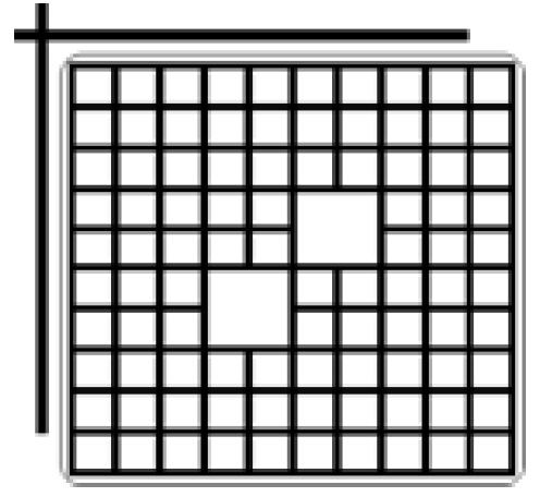
From Figure 2 in small boxes a pellet with uranium or a mixture of uranium and gadolinia can be introduced. Big boxes are water channels. Up to the left, a control rod is shown.
The reactor core operation time is divided in two kind of periods: the electricity generation period (named operation cycle) and the refueling period (the most spent fuel assemblies are replaced by the fresh fuel assemblies). Previously to start a cycle operation, a design stage is needed. In that stage, fresh fuel assemblies, fuel reload, and control rod patterns are optimized. In the remainer of the section, brief descriptions of these optimization problems are shown.
2.1 FUEL LATTICE DESIGN
Enriched uranium is introduced to the reactor core in the form of pellets. Gadolinia (Gd 2 O 3) is a neutron absorbent material and it is used as a burnable poison in the reactivity core control. The problem is to allocate pellets in the small boxes in Figure 2 in order to minimize the local power peaking factor (LPPF) subject to:
and
where kinf is the infinite multiplication factor of neutrons; k L t and k U t are the minor and major kinf permitted values; u i is the uranium enrichment of each one of the 92 pellets; and U tar is the required uranium enrichment of the fuel lattice. Uranium enrichment and gadolinia concentrations can be chosen of the elements of the Table 1.
2.2 FUEL ASSEMBLY DESIGN
As it was said, a fuel assembly is a vertical array of 25 positions. One node at the bottom and two nodes at the top of the fuel assembly typically contain fuel lattices with natural uranium, in order to reflect neutrons into the core. The other 22 nodes are divided in three zones, where each zone has a different fuel lattice. A typical zones distribution is the following: bottom zone has 10 nodes; second zone has 6 nodes and the top zone has 8 nodes. Normally, the fuel lattice of the bottom zone is optimized, and the upper zones have the same uranium enrichment but different gadolinia concentration.
2.3 FUEL RELOAD DESIGN
At the end of the cycle, the most spent fuel assemblies are substituted by fresh fuel assemblies. Fresh and spent fuel assemblies must be re-allocated into the core in order to maximize the energy production subject to:
where FLPD current and FLPD max are the current and the maximum fraction to linear power density, MAPRAT current and MAPRAT max are the current and the maximum fraction to the average planar linear generation rate, FLCPR current and FLCPR max are the current and the maximum fraction to the critical power ratio and SDM current and SDM min are the current and the minimum cold shutdown margin. FLPD current , MAPRAT current , FLCPR current and SDM current are calculated by SIMULATE-3 (Dean, 2005).
2.4 CONTROL ROD PATTERNS DESIGN
Control rods are used to compensate the burnup of the uranium in order to keep the chain reaction. A control rod can be positioned in 25 axial places. Normally, 6 intermediate axial positions are not used due to when a control rod is put in these positions, the axial power distribution is distorted. Thus, the problem is to determine the axial positions of the red control rods (see Figure 1) in order to minimize the differences between a target power distribution and the current power distribution subject to restriction of Equations 3, 4 and 5. In addition, reactor critically must be fulfilled.
3. OPTIMIZATION SYSTEM DESCRIPTION
In order to optimize the cycle operation, a new system was developed. A recurrent neural network to optimize fuel lattices was used. A local search technique to build the fuel assembly was used. Another recurrent neural network to optimize the fuel reload was used. Finally, an ant colony to optimize the control rod patterns was used. In the rest of the section, the description of the way the heuristic techniques were used to solve these problems is shown.
3.1 FUEL LATTICE OPTIMIZATION WITH A RECURRENT NEURAL NETWORK
The Hopfield’s neural network is a recurrent neural network. The response of the neurons is a bi-valued output. This kind of neural network has associated an energy function that measures the energy of the neural net- work. With appropriate changes in the responses of the neurons, the energy can be minimized. A generalization of this model was proposed by Mérida-Casermeiro, Galán-Marín, and Muñoz-Perez (2011). The responses of neurons can be multi-values in the interval [0, ...N ], where N is the number of elements in the Table 1. For fuel lattice optimization, the recurrent neural network has 47 neurons equivalent to 47 pellets that can be introduced into a half fuel lattice. A half fuel lattice can be seen when a line from control rod corner to corner without control rod in Figure 2 is drawn. Besides, a water channel is formed by the space of 4 positions. The response of neurons corresponds with an uranium enrichment and gadolinia concentrations of Table 1. The set of neurons’ responses is named the global neural state (GNS). The neurons have to change their responses in order to minimize the energy of the neural network. The energy function to solve the fuel lattice optimization is the following:
where k tar inf is the target kinf value, and is determined previously with the linear reactivity model (Driscoll, Downar, & Pilat, 1990); LPPF (GNS) and kinf (GNS) means that these lattice parameters depends on global neural state. These variables are calculated by CASMO-4 code (Edenius, 2004). For more details about this neural network and its implementation to solve this problem, you can read Ortiz et al. (2009).
3.2 FUEL ASSEMBLY BUILDING WITH A LOCAL SEARCH TECHNIQUE
Upper zones in the fuel assembly are built using the pellets distribution found by the recurrent neural network in the previous step. Only gadolinia concentrations are changed. The space solutions to change gadolinia in the just optimized fuel lattice is small. So, a sophisticated optimization heuristic to solve this problem is not required. It is enough to implement a simple local search and to choose the one that has the minimum LPPF value.
3.3 FUEL RELOAD OPTIMIZATION WITH A RECURRENT NEURAL NETWORK
Another recurrent neural network with 111 neurons to optimize the fuel reload was used. In a quarter reactor core (see the Figure 1), there are 111 channels. Fresh and burnt fuel assemblies are sort according to their burnup level and an integer number is assigned to each one. The response of neurons is an integer number in the interval of [1, ..., M ], where M is the number of the channels in the quarter core. So, if neuron A has the integer B, like response, it means that in channel number A the fuel assembly number B (according to burnup level) is introduced. Also, the global neural state is named to the set of neuron’s response. A global neural state is a possible fuel reload to be used in the reactor core. Responses of neurons have to be changed in order to minimize the energy value of the recurrent neural network. That energy function is the following:
where C is a positive constant in order to do not have negative values in energy function; keff is the effective multiplication factor of neutrons at the end of the cycle; FLPD(GNS) Curr , MAPRAT (GNS) Curr , FLCPR(GNS) Curr and SDM (GNS) Curr depend on global neural state and were previously de- fined; FLPD Max , MAPRAT Max , FLCPR Max , and SDM Min are the limit values to the thermal limits and the cold shutdown margin, respectively; w i are weighting factors.
3.4 CONTROL RODS PATTERNS OPTIMIZATION WITH AN ANT COLONY SYSTEM
Ant colony system emulates the behaviour of real ants and their ability to build short paths between their nest and the food sources. Real ants can build such short path because they communicate between them depositing a substance named pheromone (ρ). When a real ant finds a pheromone trail, the probability to follow it is high. The ants spend more time to go through long trails and the pheromone deposit rate is lower than short trails. On the other hand, the pheromone evaporates with the passage of the time. So, long trails disappear easily, and short trails endure. To optimize control rods patterns, red control rods in a quarter core will be used (see Figure 1), it is to say 8 control rods. The artificial ants must decide an axial position to insert each one of 8 control rods in the core. The artificial ants deposit pheromone in each axial position depending on the convenience of the axial position. The most convenient axial positions have more pheromone than those with less convenience to be used. For example, if an axial position helps to mitigate a peak power or kept the reactor in critical state, it is more convenient to be chosen. For each axial position is possible to define a convenience level (Λ) to mitigate power peaks or the control rod worth. An artificial ant decides to use an axial position in function of the pheromone deposits and the convenience level. Ant colony system uses three rules to operate and they are showing up next:
the i-th control rod will be inserted in the j-th axial position with maximum product of pheromone and convenience level. β is a constant greater than zero. The pheromone is updated by each ant once it has chosen the j-th axial position for i-th control rod. It is done with the following equation:
where ε is the evaporation rate whose values are in the interval ([0, 1]), the pheromone is updated by fixing increments denoted by ρ 0. Once that all ants have proposed a control rod pattern, they are evaluated by SIMULATE-3 code (Dean, 2005). The best control rod pattern receives an extra pheromone, and it is updated according to:
where keff tar is the target keff and Ɯi are weighting factors.
3.5 FLOW DIAGRAM
Figure 3 the flowchart of the system is shown.
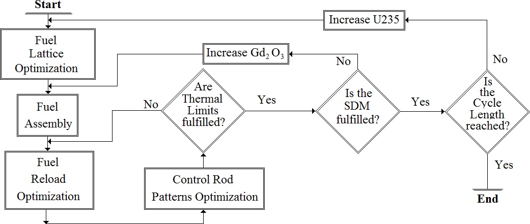
System starts optimizing the fuel lattice of the bottom fuel assembly according to the average uranium enrichment and gadolinia requirements. Then upper fuel lattices are found with the local search technique. An initial fuel reload is obtained with the recurrent neural network. The involved variables in Eq. 8 are obtained with SIMULATE-3 running a Haling calculation at the first iteration of the system. The next step is to optimize control rods patterns with the ant colony system. If thermal limits are not fulfilled, then a new fuel reload is optimized. Control rod patterns are simulated by SIMULATE-3 to obtain the variables of Eq. 8 from second iteration until a stop criterion is fulfilled. If cold shutdown margin is not fulfilled, then gadolinia concentration is increased and a new fuel assembly is made. Finally, if energy requirements are not reached,then the average uranium enrichment is increased 0.01% U235 and a new fuel lattice must be optimized.
4. RESULTS
In order to test the capabilities of the new system, a cycle operation of 18 months of cycle length was used. This cycle has two types of fresh fuel assemblies, both have 3.66% of uranium enrichment but different gadolinia concentration. 60 fresh fuel assemblies of the type one are loaded into the core and this type is named FA1. 52 fuel assemblies of the type two are loaded into the core and the type is named FA2. This cycle has a length equal to 10.9 GWD/MT. For that burnup, the target keff is equal to 0.9972. FLPD max , MAPRAT max and FLCPR max are equal to 0.96. SDM min is equal to 1.2%.
In Table 2 core and fuel lattice’s parameters of several executions of the system are shown. As can be seen, thermal limits of all executions are lower than the upper limit (0.960), also all cold shutdown margins values are greater than 1.2%. The required keff to guarantee the energy specifications is 0.9972. In all executions the keff values are greater than the required value. So, system can find a complete solution of all involved problems in the in-core fuel management. Besides, cases 5, 6 and 8 have a high enough keff value to generate more energy than 10.9 GWD/MT.
Table 2 Core parameters of cycle operation.
| Case | LPPF | kinf | FLPD | MAPRAT | FLCPR | SDM% | keff |
| 1 | 1.215 | 1.17012 | 0.951 | 0.902 | 0.908 | 1.210 | 0.99720 |
| 2 | 1.246 | 1.16419 | 0.949 | 0.938 | 0.889 | 1.513 | 0.99770 |
| 3 | 1.275 | 1.17519 | 0.942 | 0.867 | 0.932 | 1.515 | 0.99753 |
| 4 | 1.317 | 1.08461 | 0.958 | 0.948 | 0.936 | 1.536 | 0.99785 |
| 5 | 1.255 | 1.16759 | 0.945 | 0.922 | 0.897 | 1.720 | 0.99927 |
| 6 | 1.257 | 1.17211 | 0.939 | 0.859 | 0.884 | 1.552 | 0.99970 |
| 7 | 1.250 | 1.14790 | 0.942 | 0.867 | 0.932 | 1.515 | 0.99753 |
| 8 | 1.277 | 1.17784 | 0.951 | 0.927 | 0.914 | 1.547 | 0.99843 |
| Ref | <0.960 | <0.960 | <0.960 | >1.200 | ≥0.9972 |
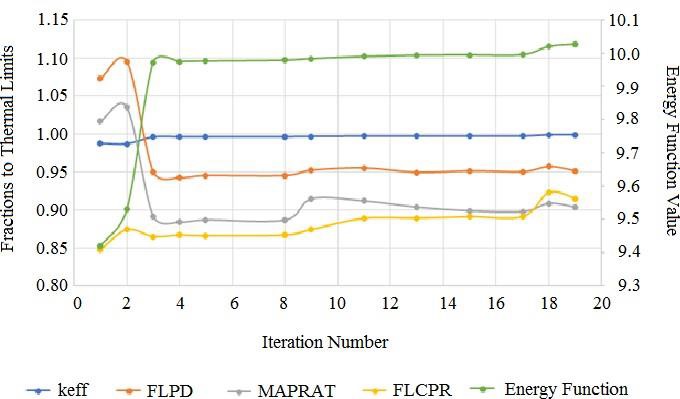
In Figure 4, a typical evolution of the fuel lattice optimization is shown. It can be seen that the energy function value decreases when the number of iterations increases and also LPPF value is decreased. In Figure 5, a typical evolution of the parameters of a fuel reload optimization is shown. It can be seen that the energy function value decreases when the number of iterations increases, and also thermal limits are decreased below 0.96.

In Figure 6, a typical pheromone evolution is shown. It can be seen that at the starting of optimization, the pheromone is accumulated in the axial position 32. However, the ants change the position of that control rod and it is inserted at axial position 02. Similar graphs are built for all control rods in the core. At the end of the optimization process, the ants assign the axial position according to the pheromone accumulation. It is difficult to graph pheromone and thermal limits evolution in the same figure, but according to pheromone is accumulated, the thermal limits and the critically state are fulfilled.

5. CONCLUSIONS
In this paper a new methodology to optimize cycle operations in BWRs was shown. The heuristic techniques called recurrent neural networks and an ant colony system were used to solve the involved combinatorial optimization problems. It was shown that the energy function of recurrent neural networks has good convergence towards minimum values. Also, pheromone accumulation works to improve thermal limits and keff value throughout the cycle. This methodology is able to find solutions to all problems of the in-core fuel management so that thermal limits, cold shutdown margin are fulfilled and energy requirements are reached.

