


 nueva página del texto (beta)
 Inglés (pdf)
 Artículo en XML
 Referencias del artículo
 Enviar artículo por email
 Citado por SciELO
  Similares en
SciELO
Similares en
SciELO 
 Permalink
1. Introduction
Recent advances in solid state conversion technology have led to the proliferation of variable frequency induction motor drives (VFIMDs) that are used in several applications such as air conditioning, blowers, fans, pumps for waste water treatment plants, textile mills, rolling mills, etc. (Bose, 1998). The most practical technique in VFIMDs is direct torque controlled strategy in that it offers better performance rather than the other control techniques. The direct torque controlled technique is implemented in a voltage source inverter which is mostly fed from a six-pulse diode bridge rectifier, insulated gate bipolar transistors (IGBTs) are employed as the VSI switches. The most important drawback of the six-pulse diode-bridge rectifier is its poor power factor injection of current harmonics into ac mains. The circulation of current harmonics in the source impedance yields in harmonic polluted voltages at the point of common coupling (PCC), resulting, consequently, in undesired supply voltage conditions for costumers in the vicinity. The value of current harmonic components which are injected into the grid by nonlinear loads such as DTCIMDs should be confined within the standard limitations. The most prominent standards in this field are the IEEE standard 519 (IEEE Std 519, 2014) and the International Electro-Cechnical Commission (IEC) 61000-3-2 (IEC Standard 61000-3-2, 2004). And the International Electro-technical Commission (IEC) 61000-3-2 (IEC Standard 61000-3-2, 2004).
Arc furnaces generate more harmonic current distortion and Static Power Converters (SPC’s) are the harmonic current source with the widest distribution in electrical systems. Power quality can be improved by employing passive or active filters (Darvishi, Alimardani, Vahidi, & Hosseinian, 2014; Eswaran & Kumar, 2017; Khaledian, Vahidi, & Abedi, 2014). Passive filters cause additional losses, need additional floor area and are complex in design as their performance is affected by changes in frequency. Similarly, active filters are also costly and complex, and have ratings comparable to the load rating. The use of multipulse AC-DC converters is one such technique for harmonic mitigation and is found to be rugged and reliable. This method uses two or more bridge converters, where the harmonics generated by one converter are cancelled by another converter by a proper phase shift. For DTCIMD’s one effective solution is to employ multipulse AC-DC converters. These converters are based on either phase multiplication or phase shifting or pulse doubling or a combination (Abdollahi, 2012h; Abdollahi, 2012i; Abdollahi, 2017a; Abdollahi and Jalilian, 2011; Abdollahi & Jalilian, 2012b; Paice, 1996; Singh, Bhuvaneswari, & Garg, 2007b). Although, in the conditions of light load or small source impedance, line current total harmonic distortion (THD) will be more than 5% for up to 18-pulse AC-DC converters (Singh, Bhuvaneswari, & Garg, 2007c; Singh, Garg, & Bhuvaneswari, 2007d). A Hexagon-Connected Autotransformer-Based 20-pulse AC-DC converter is reported in (Abdollahi, 2012a) which has THD variation of 5.18% to 7.20% from full-load to light-load (20% of full-load). A Zigzag-Connected Autotransformer-Based 24-pulse AC-DC converter is reported in (Abdollahi, 2015a) which has THD variation of 3.95% to 5.85% from full-load to light-load (20% of full-load). Another T-Connected Autotransformer-Based 24-Pulse AC-DC Converter has also been presented in (Singh, Bhuvaneswari, & Garg, 2006a), however, the THD of the supply current with this topology is reported to vary from 2.46% to 5.20% which is more than 5% when operating at light load.
For mitigating the total harmonic distortion (THD) problems observed in the input currents, in (Abdollahi, 2012b; Abdollahi, 2012c; Abdollahi, 2012d; Abdollahi & Jalilian, 2012a; Abdollahi, 2015b; Abdollahi, 2017b; Singh, Bhuvaneswari, & Garg, 2006b; Singh, Bhuvaneswari, Garg, & Chandra, 2006d; Singh, Garg, & Bhuvaneswari, 2006e; Singh, Bhuvaneswari, & Garg, 2007a) Abdollahi and Singh propose 30 and 36-pulse AC-DC converters while the power quality enhancement was the main concern. High magnetic ratings and higher degree of complexity are the major shortcomings of the previous works. The 36-pulse one was designed for vector controlled induction motor drives in (Singh, & Gairola, 2007) which has THD variation of 2.03% to 3.74% from full-load to light-load (20% of full-load) respectively but the dc link voltage is higher than that of a 6-pulse diode bridge rectifier, thus making the scheme nonapplicable for retrofit applications. Different 36-pulse ac-dc converters have been presented based on autotransformer platform (Abdollahi, 2012f; Abdollahi, 2012g; Abdollahi, 2015c) for reducing the total harmonic distortion (THD) of the ac mains current. But these topologies are not suitable for the isolated industrial application.
To improve the harmonic reduction capability and to meet the IEEE-519 and IEC 1000-3 standards, the pulse multiplication in general and pulse doubling or dc side ripple re-injection in MPCs has been proposed (Meng, Yang, Zhu, Gao, & Yang, 2015a). The pulse ultiplication technique improves power quality both input ac and output dc side of ac-dc converters with reduced magnetic rating. However, limitation like double increase of amplitude high order harmonics and difficulty to determine turn ratio for multi-tapped IPR which affect the harmonic suppression remarkably (Wang, Yang, & Yang, 2015). Also in an autotransformer based MPC, an electrical isolation between the parallel DBR units is necessary for normal operation of rectifier with current injection technique (Meng, Yang, & Yang, 2011). Zero sequence blocking transformer is widely used to ensure independent operation of rectifier units. ZSBT blocks zero-sequence components by offering high impedance path and prevent interbridge currents with kVA rating about 8% of load. In nonisolated MPC, double-active IPRs are employed for independent operation of DBR units in place of ZSBT and the kVA rating of which is about 15% of load power (Meng, Yang, Yang, & Gao, 2015b).
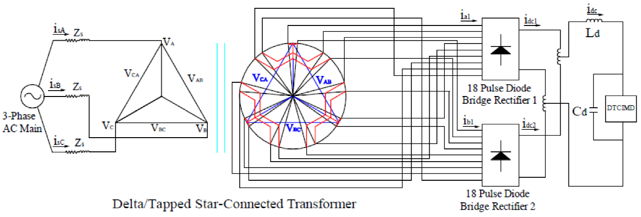
Several 40, and 72-pulse ac-dc converters have been reported (Abdollahi, & Jalilian 2012c; Abdollahi, 2013; Abdollahi, 2014; Abdollahi, 2015d; Abdollahi, 2016; Abdollahi, 2017a; Abdollahi, & Gharehpetian, 2016) for reducing the total harmonic distortion (THD) of the ac mains current. But these topologies require higher rating magnetics, resulting in the enhancement of capital cost. Increasing the number of pulses further results in improvement in various power-quality indexes but along with the additional cost of different converters and increased system complexity. Therefore, it is suggested that higher pulse configuration with less complexity must be used, so that the ac-dc conversion meets the IEEE-519 requirements. In this paper, a 36-pulse AC-DC converter is designed, modeled and simulated to feed isolated industrial loads. The proposed configuration consists of an isolation transformer based Delta/tapped star connection (shown in Fig. 1). In fact, this is a trade-off between the pulse number, transformer platform, complexity of the scheme and the cost off the configuration. The proposed scheme has an optimized configuration in this regard.
2. Proposed 36-pulse ac-dc converter
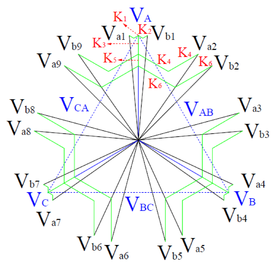
We have designed a delta/tapped star transformer based 36-pulse AC-DC converter that reduces the kilovolt-ampere (kVA). In order to implement a 36-pulse ac-dc converter, two paralleled 18-pulse bridge rectifiers (two nine-leg rectifiers) are required. In this case, two sets of nine-phase voltages with a phase difference of 40 degrees between the voltages of each group and 10 degrees difference between the same voltages of the two groups are needed. The phasor representation of the transformer for the 36-pulse AC-DC converter having tapped star connected secondary winding is shown is Fig. 2. The tapped star connection of the proposed transformer for the 36-pulse converter is shown in Fig. 3. We examined the results by simulating the proposed scheme via MATLAB/Simulink. To support the main ideas (improving the power quality indices) the output of the ordinary six-pulse circuit, and obviously the proposed 36-pulse ac-dc converters, are compared while the circuits feed a DTCIMD load. Power quality indices such as the THD of the ac source, the power factor, the displacement factor, the distortion factor, and finally, the THD of the voltage source at the PCC are studied.
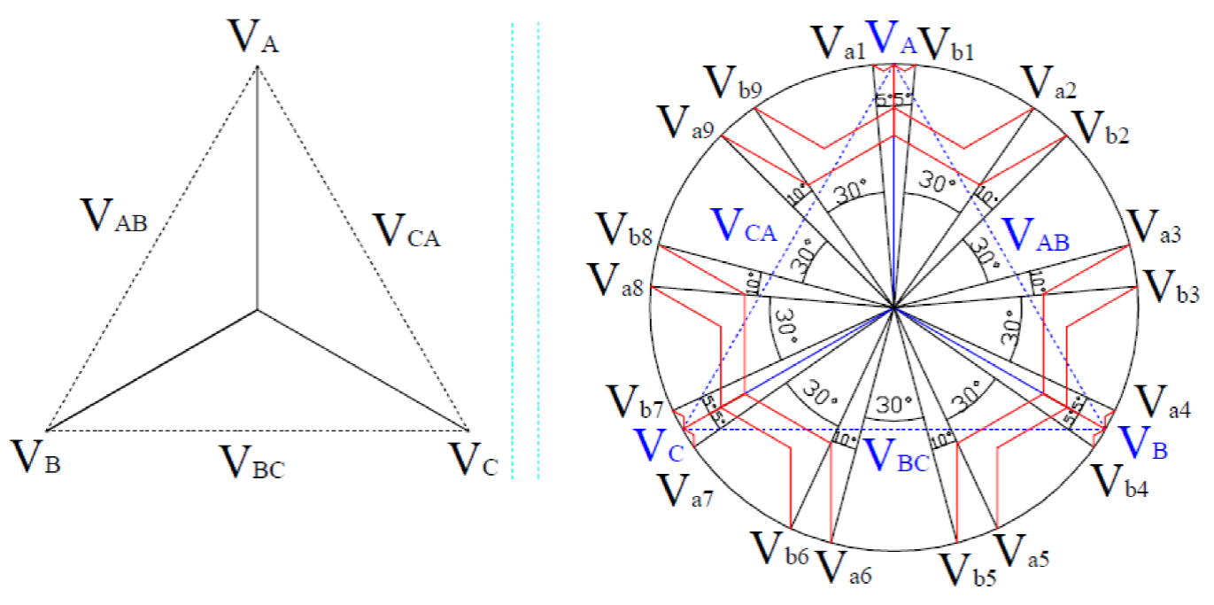
Fig 2 Phasor representation of transformer for 36-pulse AC-DC converter having tapped star connected secondary winding
A. Design of Proposed Transformer for 36-Pulse AC-DC Converter
Both sets of voltages illustrated in Figure 1 (Va1, Va2, Va3, Va4, Va5, Va6, Va7, Va8, Va9, and Vb1, Vb2, Vb3, Vb4, Vb5, Vb6, Vb7, Vb8, Vb9) are connected to rectifiers I and II. The corresponding members of each group are 10 degrees phase shifted. For instance, Va1 and Va2 leads and lags the reference voltage (Va) with +5 and -5, respectively.
These voltages are constructed using the combinations of 3-phase input voltages. The required combinations are achievable by the appropriate arrangement of the tapped star-connected autotransformer. Equations (4) and (5) explain the appropriate combinations.
Where, nine-phase voltages are:
Input voltages for converter I are:
Input voltages for converter II are:
Constants K1-K6 are calculated using (2), (3), (4), (5) and (6) to obtain the required windings turn numbers to have the desired phase shift for the two voltage sets:
B. Design of Transformer for Retrofit Applications
For retrofit applications it is not practical to have a higher voltage in the dc link in comparison to the output of the 6-pulse converter. For instance, with the transformer arrangement of the proposed 36-pulse converter, the rectified output voltage is 17% higher than that of the six-pulse rectifier, as shown in Fig. 4.
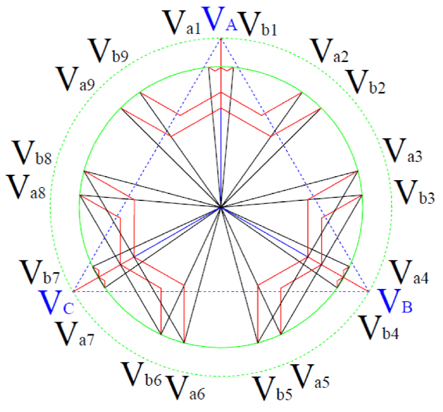
Fig. 4 Phasor diagram of voltages in the proposed transformer connection along with modifications for retrofit arrangement.
As in Section II, Part 1, the following equations can be derived as:
Accordingly, the values of constants K1-K6 are changed for retrofit applications as:
It is remarkable that the constants indicate the appropriate number of turns that should be provided in the tapped star-connected transformer windings. The modified connection will not be useless any more for retrofit applications.
3. SIMULATIONS via Matlab/Simulink
We simulate our proposed configuration via Matlab/Simulink software in the (PSB) toolbox environment. The AC supply utility has the following specifications: three-phase 460 V and 60 Hz. This AC-supply is connected to the 36-pulse converter. It should be mentioned that we use three multi-winding transformers defined in the library of PSB to model the delta/tapped star transformer. The multi-winding transformer of this library was also adopted to model both ZSBT and tapped IPT (shown in Fig. 5).
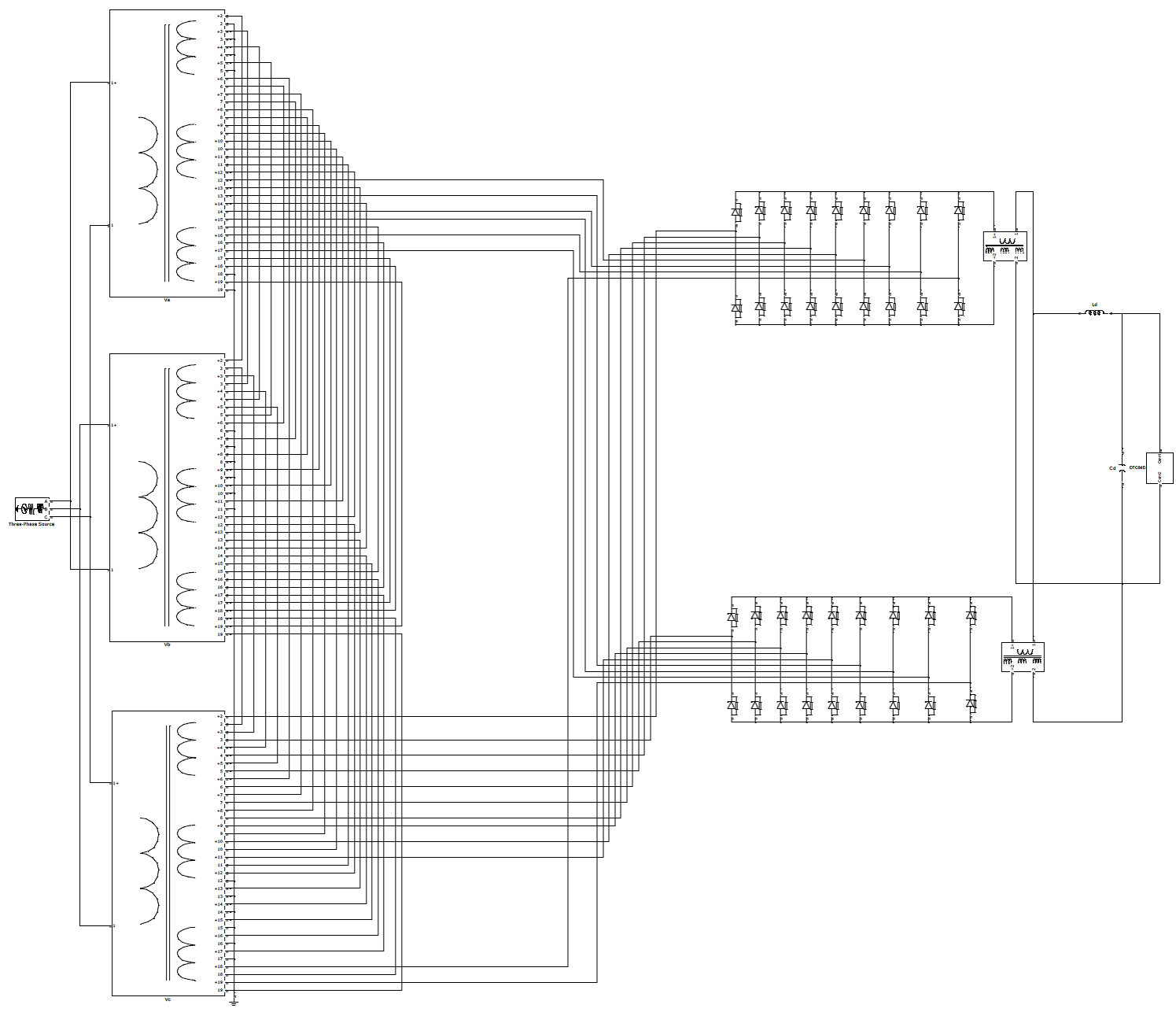
At the converter output (dc link), a series block, consisting an inductance (L) and a parallel capacitor (C) are connected in the output terminals of the circuit (e.g. DC link), to supply the IGBT-based voltage source inverter (VSI). In turn, VSI feeds a squirrel cage induction motor in which direct torque controlled strategy is applied to control the motor speed. Technical specifications of the simulated induction motor are as follows: name plate power: 50 hp (37.3 kW), number of poles: 4-pole, connection type: Y-connected. The detailed data are provided in the Appendix for the motor we have simulated here.
4. Results and discussion
Figures 6, 7, 8, 9 , 10, 11, 12 and 13 illustrate the results of the simulation performed. Two groups of nine-phase voltages, which have 10 degrees of phase shift with respect to other waves of the group, are shown in Figure 6. As shown in Fig. 7, the specification of the output voltage for the 36-pulse converter is as follows: the waveform represents a smooth behavior which has no ripples. The DC component has the value of 607.8 V. It is remarkable that this voltage is almost equal to the DC link that is generated by a six-pulse rectifier (607.6 V). This feature makes it possible to use the proposed 36-pulse scheme for retrofit applications.
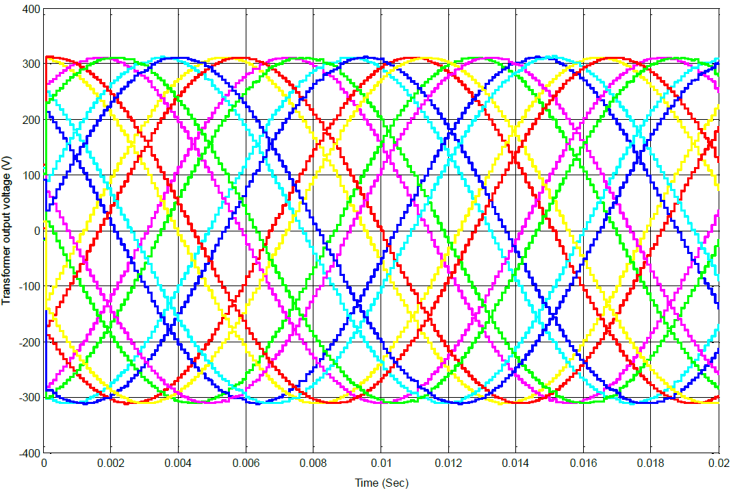
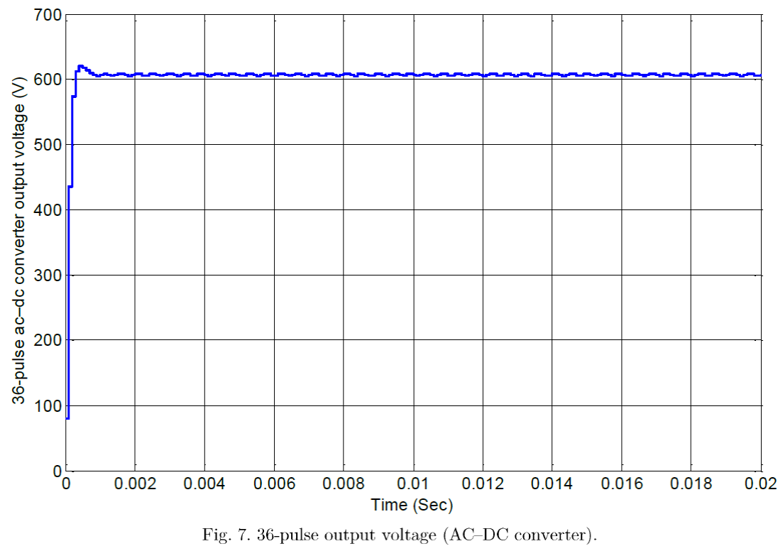
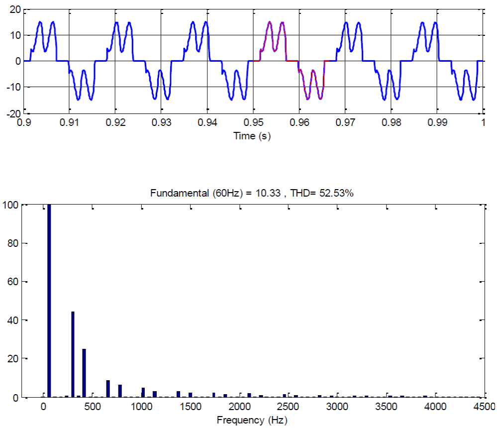
Fig. 8 Six-pulse AC-DC converter input current waveform at light load condition including the harmonic spectrum.
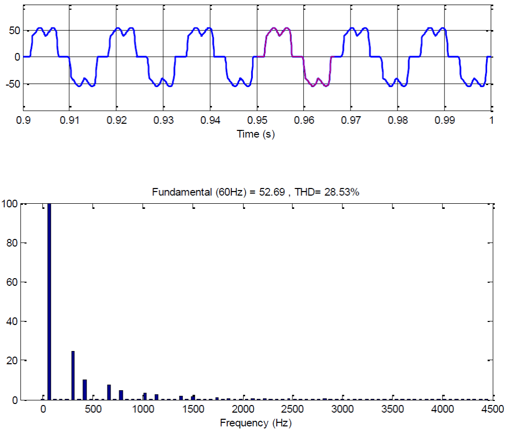
Fig. 9 Six-pulse AC-DC converter input current waveform at full load condition including the harmonic spectrum.
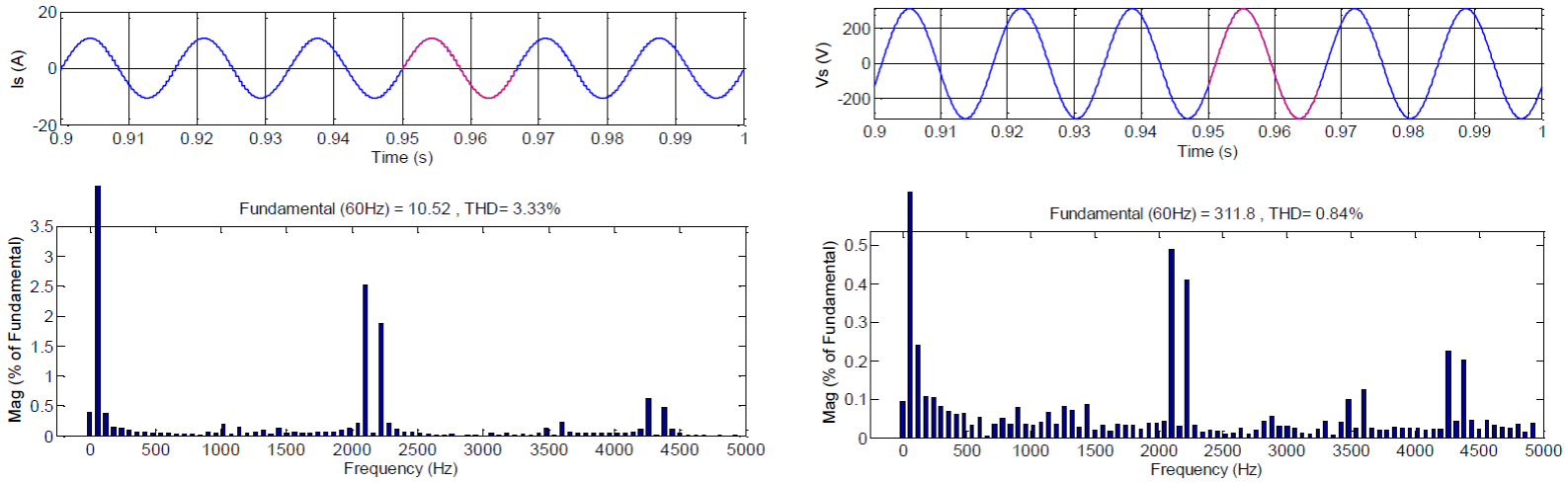
Fig. 10 36-pulse AC-DC converter input current and voltage waveforms at light load condition including the harmonic spectrum.
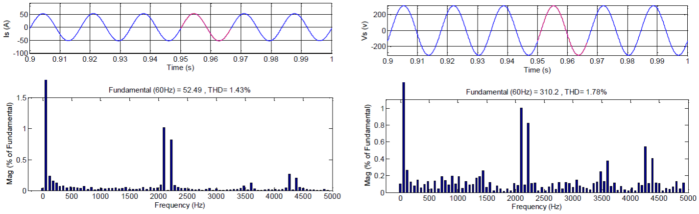
Fig. 11 36-pulse AC-DC converter input current and voltage waveforms at full load condition including the harmonic spectrum.
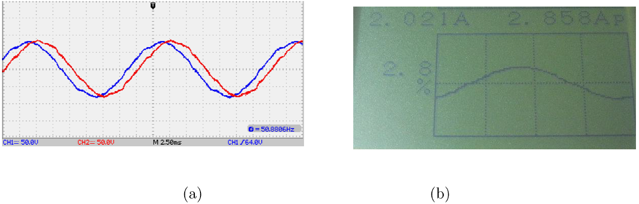
Fig. 12 (a) Output voltage waveforms of delta/tapped star transformer, (b) Input current waveform and its THD of proposed 36-pulse ac-dc converter.
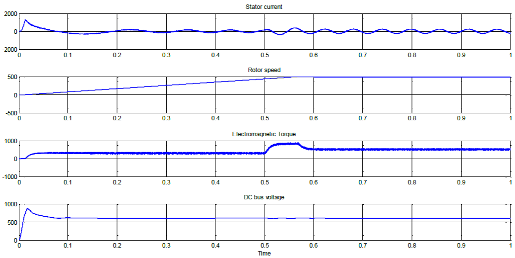
Fig. 13 Waveforms depicting dynamic response of 36-pulse diode rectifier fed DTCIMD with load perturbation (source current isA, speed ωr , developed electromagnetic torque Te , and dc-link voltage Vdc ).
To show the priority of the proposed 36-pulse scheme in the reduction of input current harmonic content, Figs. 8, 9, 10 and 11 compare this wave form for 6-pulse, and 36-pulse converters. Considering the requirements of the IEEE standard 519, the proposed 36-pulse scheme. It should be noted that these input currents are extracted while the converter is supplying an induction motor which is operated under two load scenarios: 1) light load condition (namely 20% of full load) and 2) full load. As can be seen from Figures 8 and 9, the THD for a conventional 6-pulse converter reaches the value of 28.53%, in light load, and 52.53%, for full load condition. It is obvious that the THD does not meet the IEEE-519 requirements. Moreover, the harmonic analysis confirms the presence of low order harmonics in the spectrum which is not a practically acceptable performance.
In case of the proposed 36-pulse converter, a significant reduction is observed in the values of current and voltage THD in the simulation results. As seen from Figures 10 and 11, the schemes reached THDi=1.43% and THDv=1.78%, for full load condition, and THDi=1.43% 3.33% and THDv=0.84%, for light load condition. However, the 36-pulde converter also could not meet the requirements of the IEEE-519 standard, which demonstrates a value of 4% for THD to be practically acceptable. An achievement for this proposed scheme is that low order harmonics are diminished in the input current harmonic spectrum (up to 33rd harmonic are eliminated). It should be noted that it is not just the THD that is improved using the proposed scheme. In order to verify the simulation results and demonstrate the applicability of the proposed topology, a laboratory prototype of the proposed 36-pulse converter is constructed. The experimental results confirm the simulation results. The output voltage waveforms of the delta/tapped star transformer, the input current waveform and the THD of the proposed 36-pulse ac-dc converter are depicted in Figs. 12(a) and 12(b), respectively.
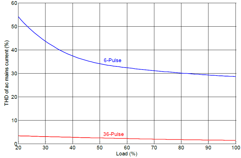
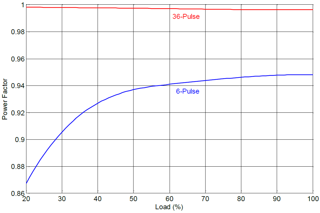
Different output and input characteristics of the proposed 36-pulse converter feeding DTCIMD such as supply current, rotor speed, electromagnetic torque, and DC link voltage are shown in Fig. 13. These waveforms can be compared to their equivalent parameters of a six-pulse fed DTCIMD that are shown in Fig. 14. The dynamic characteristics of the two converters can be used to compare their dynamic response through conditions such as starting or load variations. Power quality indices such as displacement power factor (DPF) voltage THD, distortion factor (DF), and power factor (PF) are also improved by the proposed configuration. Table 1, illustrates the mentioned indices which are obtained for different loading conditions. As expected, a significant improvement is observed for the proposed configuration in comparison to the circuits using lower pulse numbers. It is remarkable that the AC supplying source has a unity power factor in the presence of the 36-pulse proposed topology in the loading range of the induction motor. Table 2 indicates that, for all over the loading, the 36-pulse converter shows its superiority in comparison to the other configurations. As can be seen, it keeps current THD less than 4% in the motor loading range. For all the aforementioned converters, the input current THD and the variations of the power factor are depicted in Figs. 15 and 16, respectively. The results also unveil the superiority of the proposed configuration. As can be observed, the power factor is almost while applying the proposed scheme. Moreover, for the worst case scenario (light loading condition, current THD remains lower than 4% for the proposed topology.
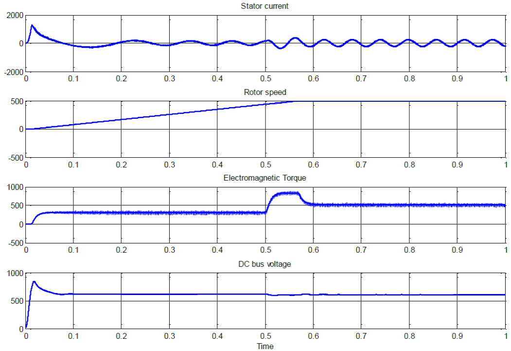
Fig. 14 Waveforms depicting dynamic response of six-pulse diode rectifier fed DTCIMD with load perturbation.
Table 1 Comparison of simulated power quality parameters of the VCIMD fed from different AC-DC converters.
| Sr. No. | Topology | % THD of Vac | AC Mains Current ISA (A) | % THD of ISA, at | DIstortion Factor, DF | DIsplacement Factor, DPF | Power Factor, PF | DC Voltage (V) | ||||||
|---|---|---|---|---|---|---|---|---|---|---|---|---|---|---|
| Light Load | Full Load | Light Load | Full Load | Light Load | Full Load | Light Load | Full Load | Light Load | Full Load | Light Load | Full Load | |||
| 1 | 6-pulse | 5.64 | 10.33 | 52.69 | 52.53 | 28.53 | 0.8850 | 0.8730 | 0.9485 | 0.9599 | 0.9858 | 0.9881 | 616.6 | 607.6 |
| 2 | 36-pulse | 1.78 | 10.52 | 52.49 | 3.33 | 1.43 | 0.9994 | 0.9998 | 0.9988 | 0.9966 | 0.9982 | 0.9964 | 611.4 | 606.4 |
Table 2 Comparison of power quality indices of proposed 36-pulse AC-DC converter.
| Load (%) | THD (%) | CF of Is | DF | DPF | TPF | RF(%) | |
|---|---|---|---|---|---|---|---|
| IS | VS | ||||||
| 20 | 3.33 | 0.84 | 1.413 | 0.9994 | 0.9988 | 0.9982 | 0.003 |
| 40 | 2.70 | 1.18 | 1.414 | 0.9996 | 0.9981 | 0.9977 | 0.003 |
| 60 | 2.16 | 1.45 | 1.414 | 0.9997 | 0.9974 | 0.9971 | 0.004 |
| 80 | 1.72 | 1.60 | 1.414 | 0.9998 | 0.9969 | 0.9967 | 0.003 |
| 100 | 1.43 | 1.78 | 1.414 | 0.9998 | 0.9966 | 0.9964 | 0.002 |
5. Conclusions
The design process of an isolated delta/tapped star transformer is explained in this paper which is then applied to develop a 36-pulse ac-dc converter. This converter in turn consists of two 18-pulse nine-phase rectifiers which are connected in parallel. To cope with the requirements of retrofit applications, some modifications are performed in the designing process. These increasing results in improving the power quality indices at the point of a common connection. Moreover, it reduces the size, weight, and volume of the circuit, especially the magnetically coupled parts. Simulation and experimental results confirm that the proposed scheme meets the requirements of IEEE- 519 related to the input current THD. It is shown that current THD is less than 4% while supplying a motor from light load condition to full load condition. In addition, it is concluded that the power factor of the AC source almost unity that would reduce the amplitude of current required to drive the DTCIMD loads. To sum up, our proposed 36-pulse ac-dc converter configuration could be applied instead of a conventional 6-pulse converter, while it makes a great reduction in kilovolt-ampere (kVA) rating, considering that the proposed configuration does not increase the cost for replacing the existing system layout and equipment.

