


 nueva página del texto (beta)
 Inglés (pdf)
 Artículo en XML
 Referencias del artículo
 Enviar artículo por email
 Citado por SciELO
  Similares en
SciELO
Similares en
SciELO 
 Permalink
1. INTRODUCTION
Lanyard wire ropes or cable assemblies are cables which are comprised of many spiralled bundles of wire. In general, lanyard terminus ends are equipped with connectors which make it possible to attach them to other fall protection system (Baszczynski, 2007). This covers a very broad range of wire rope producís, and wire rope lanyards can be extensively customized to meet the needs of a multitude of applications. These are commonly used in security, holding, hanging, attaching, anchoring, lifting, supporting and pulling. The wire ropes have been designed for specific purpose depending on a particular application (Costello, 1990).
Wire rope consists of múltiple strands of wire filament which themselves are twisted together before being wound helically around a core. The number of each set of strands depends on the strength requirements for proposed application (Chaplin, 1995). The construction of lanyard wire rope is defined as nxp where n and p are number of strands and number of wires in each strand, respectively (Costello, 1990). A common lanyard wire rope is represented by as 7x19 construction which suggests that this is made up of nineteen small wires being twisted together with seven other similar bundles (Davis, 1979).
Among all other materials, stainless steel lanyard is usually found in very unique work áreas. Apart from the other features, high strength, excellent abrasión resistance and corrosión resistance are the most important characteristics (Baszczynski, 2007). Stainless steels are used in corrosive environment particularly in área of petrochemical industries and humid atmosphere (Parrott & Pitts, 2011). These wires are also coated with different plástic materials to enhance both the functional as well as appearance. The major defeets in wire ropes are by and large introduced failed due to oxidation, corrosión, excessive heat, chemical degradation etc. In addition, environmental condition particularly humid atmosphere containing sea water also initiates the degradation of wire ropes. It is to be noted that the sea water contains chlorine that corrodes the metáis in general and stainless steel in particular (Brown, 1977; Parrott & Pitts, 2011).
The present work is thus concerned with the failure analysis of a 7x19 construction lanyard wire rope which has failed during application in wet and humid environment. Wire rope is made up of 7 strands and each strand comprises 19 wires (rope length: 3 feet 6 inches). The microstructure and properties of unused wire has also been investigated and compared with the failed rope.
2. EXPERIMENTAL PROCEDURE
Initially, visual examinations of the broken lanyard wire rope were carried out and the photographs of the failed wire rope were captured using digital camera. The analyzed chemical composition of the failed wire rope is given in Table 1. It suggests that the material used for wire rope is austenitic stainless steel and conforms to AISI 304 grade. Wires were cut from the failed wire rope near the actual fractures and prepared for metallographic examination. The polished surface was etched with aquaregia (50% HC1 and 50% HN03 by volume). Microstructural characterization was done using optical microscope. The failed wires at the fractured surface were separated from the long wire rope and then bound together with a copper wire. These wires were cleaned ultrasonically in acetone to remove any dirt and other lubricant residues over the fracture surface. The fracture surfaces of the múltiple wire failed sections near actual fracture were examined under a Field Electron and Ion (FEI) make environmental scanning electrón microscope (Model: Quanta 400) to evalúate the contaminated products over the fracture surface as well as mode of fracture.
Table 1 Chemical composition of the failed wire rope.
| Element | C | S | Ni | Cr | Mn | Si | Fe |
|---|---|---|---|---|---|---|---|
| Wt. % | 0.08 | 0.002 | 8.2 | 19.7 | 1.8 | 0.92 | Balance |
As received failed rope wires were further examined using Electron Probé Micro Analyser (EPMA) to study the grain boundary constituents that have caused the degradation of microstructure. Samples were prepared as per metallographic examination and analysed in un-etched condition for EPMA examination. Back scattered electrón (BSE) image, elemental distribution mapping and line profile for different elements were analyzed using CAMECA make, SX-100 model EPMA. Quantitative
Quantitative analysis was carried out with an operating voltage of 20 kV and with a stabilized beam current of 20 nA. A LiF (Lithium Fluoride) crystal was employed to diffracting Mn Ka and Ni Ka; PET (Pentaerythritol) crystal was used for diffracting Cr Ka and Cl Ka and TAP (Thallium Acid Phthalate) crystal was employed for diffracting Si Ka X-ray lines. Pseudocrystals of PC2 having 2d valué of 98 Á was utilized for Oxygen analysis. X-ray intensities were obtained both on respective puré metallic standards and also on samples with identical operating conditions. Absolute elemental concentrations were attained using built in analytical software with essential Atomic number (Z), Absorption and Fluorescence (ZAF) correction to get accurate weight/atom percentage of constituents in the respective sample.
Wire rope strands were separated from the rope and cut to desired length for tensile testing. Tensile properties of failed, used (but not failed) and unused wire ropes were evaluated to know the máximum load bearing capacity. Room temperature tensile tests were conducted with a strand containing 19 wires on screw driven Instron (5500 R) testing machine (Instron Corporation, Norwood, MA). Three specimens were tested in each wire rope and average valúes are reported in Table 2. Fracture surfaces of tensile specimens were again examined under environmental scanning electrón microscope (SEM: FEI Quanta 400).
3. RESULTS AND DISCUSSION
The broken wire rope in as-received condition is shown in Figure l (a-c). This displays dark brownish colour. The wire rope supplied with two broken ends (Figure 1a). This consists of many small diameter wires wound together into strands and then these strands are knit jointly into a wire rope. The end fittings of the wire rope are fastened with open swaged socket. Broken end región displays several wires unwound and loosen from their strands (Figure 1b and c). Chemical composition of the wire rope indicates that the wires are made using austenitic stainless steel AISI 304 grade (Table 1).
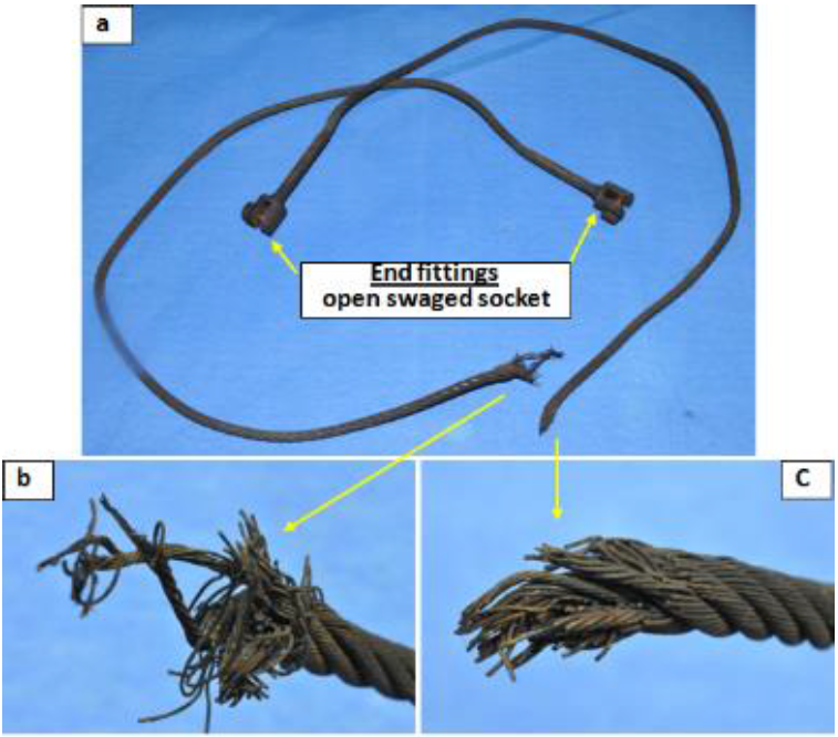
Fig. 1 Photograph of failed wire rope: (a) as-reccived condition, (b) once end of the broken rope, (c) another end of the broken rope displays several wires unwound from its strands and loosens from their strands.
Optical microstructures of failed wire rope are shown in Figure 2. This displays the presence of typical equiaxed austenitic grains along with annealing twins (Figure 2a). The average grain size is ~ 15 pm (ASTM No. 8.5). The grain size near and away from failed región appears to be same. The optical microstructure of the wire exhibits two features namely (a) overall grain size is nearly uniform from center to periphery and (b) several cracks along the grain boundaries at the periphery of the wire rope (Figure 2b and c). Presence of annealing twins within the equiaxed austenitic grains indicates that the wire rope is used in annealed condition (Figure 1,. This also suggests that the rope wires are initially prepared by wire drawing and subsequently annealed. In addition, several grains have been dislodged from periphery of the individual broken wire (Figure 2b and c). The dislodged materials have broken and separated from the wire along the grain boundaries. This clearly reveáis that the grain boundaries have significantly weakened during service. Very cióse to the fractured área, the microstructure exhibits extensive material degradation due to grain boundary weakening.
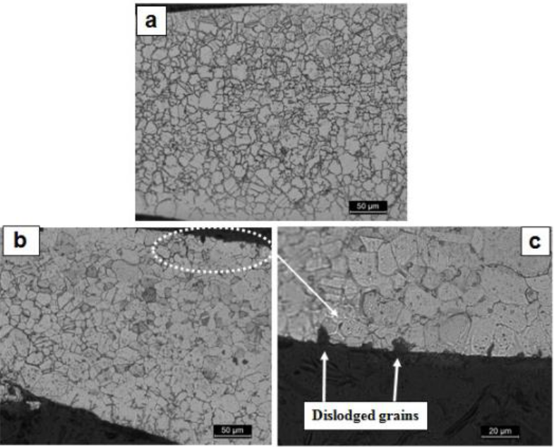
Fig. 2 Optical micrograph of failed wire rope shows (a) austenitic grain structure with annealing twins, (b) few grains are dislodged from the grain boundaries at the surface near fracture and (c) high magnification of dislodged grains.
BSE micrograph cióse to the fracture obtained in un-etched condition exhibits continuous thin film along grain boundaries (Figure 3). This observation is analogue to the optical microstructure (Figure 2). The X-ray elemental mappings of Cr, O, Cl, Ni and Mn elements of failed wire rope in un-etched condition obtained by EPMA are shown in Figure 4. Elemental distribution mapping reveáis that the grain boundaries are enriched with Oxygen, Chlorine and Chromium. On the other hand, uniform distributions of Nickel and Manganese are observed in the matrix.
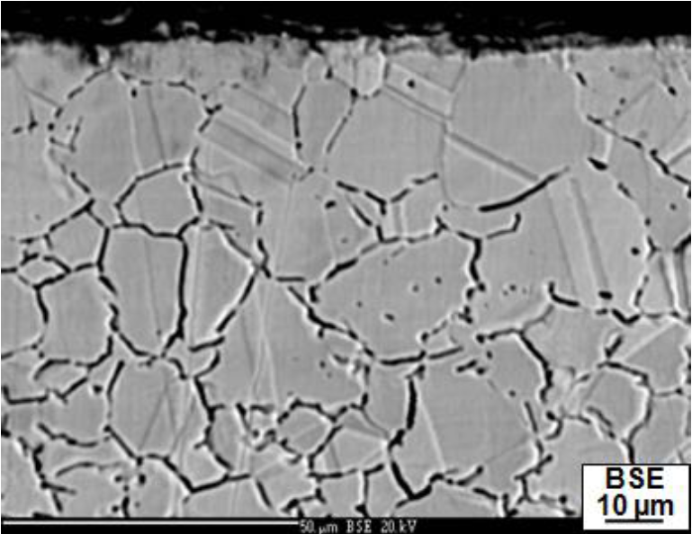
Fig. 3 EPMA-BSE microstructure of the individual wire near failed end showing dark network along grain boundaries.
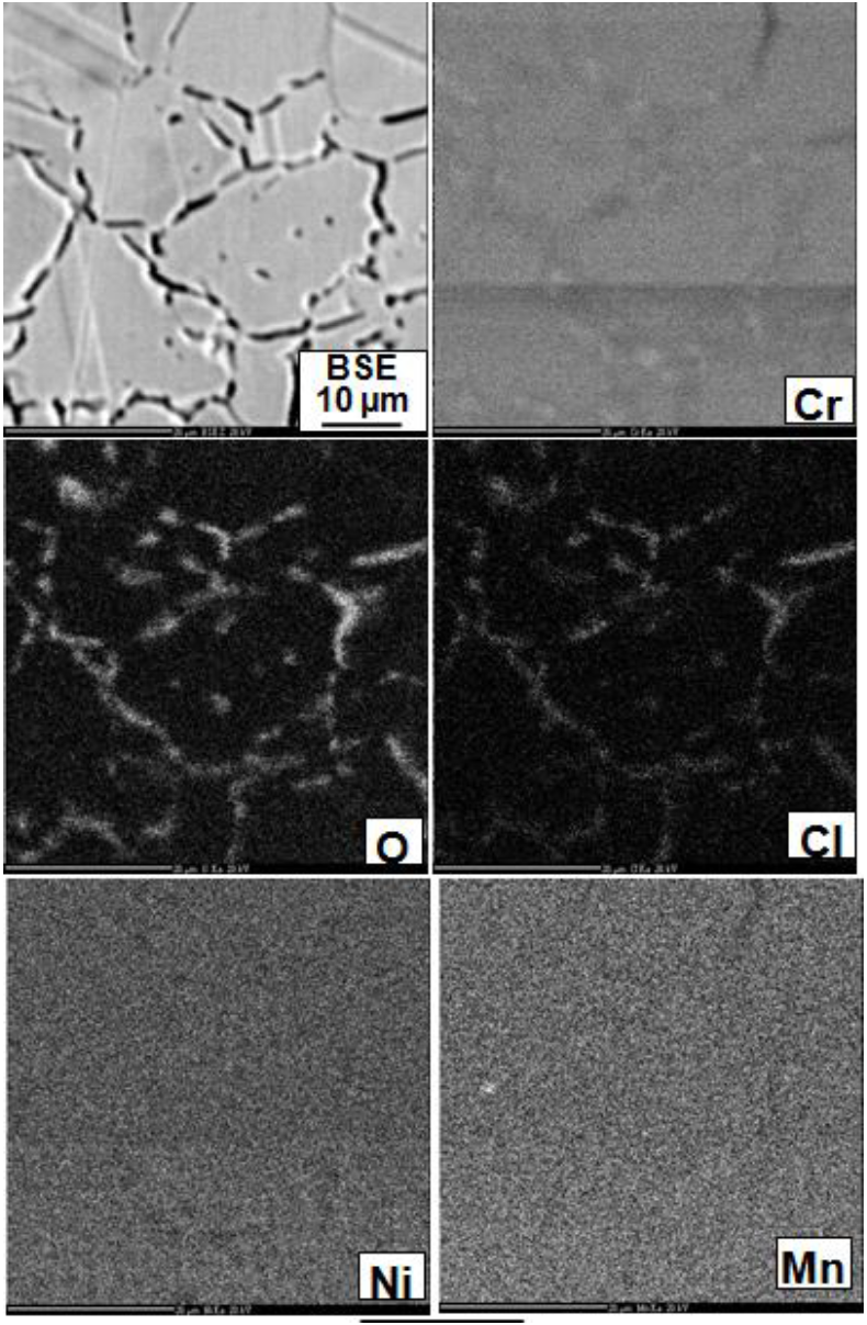
Fig. 4 X-ray elemental distribution mappings of Cr, O, C1 Ni and Mn obtained by EPMA illustrates enrichment of Cr, C1 and O along the grain boundary.
In order to confirm the results of elemental mapping, X-ray line sean technique has been employed for Oxygen Chlorine and Chromium elements and results are shown in Figure 5. This reflects evidently that the line sean profiles have validated the enrichment of Oxygen, and Chlorine at the grain boundary. Line profile has also displayed the chromium enrichment at the grain boundary as well as the depletion at either side of the grain (i.e. vicinity of grain boundary). The weakening of grain boundaries along with dislodged materials from the periphery of the wire therefore indicates that the rope is exposed to corrosive environment during the service. Presence of Cl and O at the grain boundaries in the form of thin film supports the same.
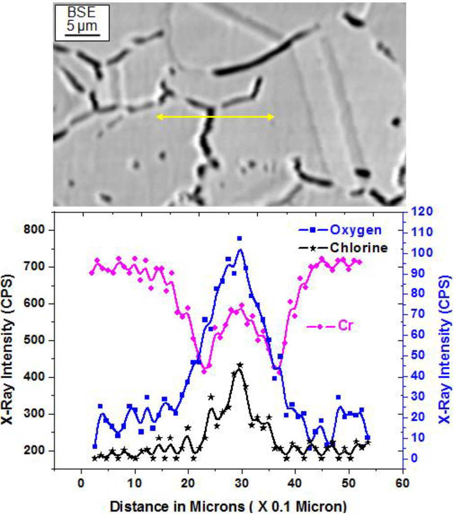
Fig. 5 EPMA Line profile of the elements O, C1 and Cr across the grain boundary demonstrates as reflected in the X-ray mappings.
The fracture surfaces of failed wire rope near the actual fractures are shown in Figure 6(a-d) . Thick layer of foreign material deposition is exhibited over the fracture surface of the individual wires and also all around the surface of each wire. In fact fracture surfaces of the failed rope have shown the presence of corrosión debris which has masked the actual fracture (Figure 6). The fracture surfaces of the wire appear to be rough and the individual wire does not show distinctive mode of fracture features. These are similar to mud cracks with oxide layer (Figure 6b-d). The Energy Dispersive Spectroscopey (EDS) spectrum taken on fracture surface of the failed rope near the actual fractures has revealed the presence of chlorine and oxygen in addition to matrix elements (Figure 7). These results are well agreement with those obtained by EPMA analysis (Figure 4 and. All the wires in the failed rope have shown similar behaviour.
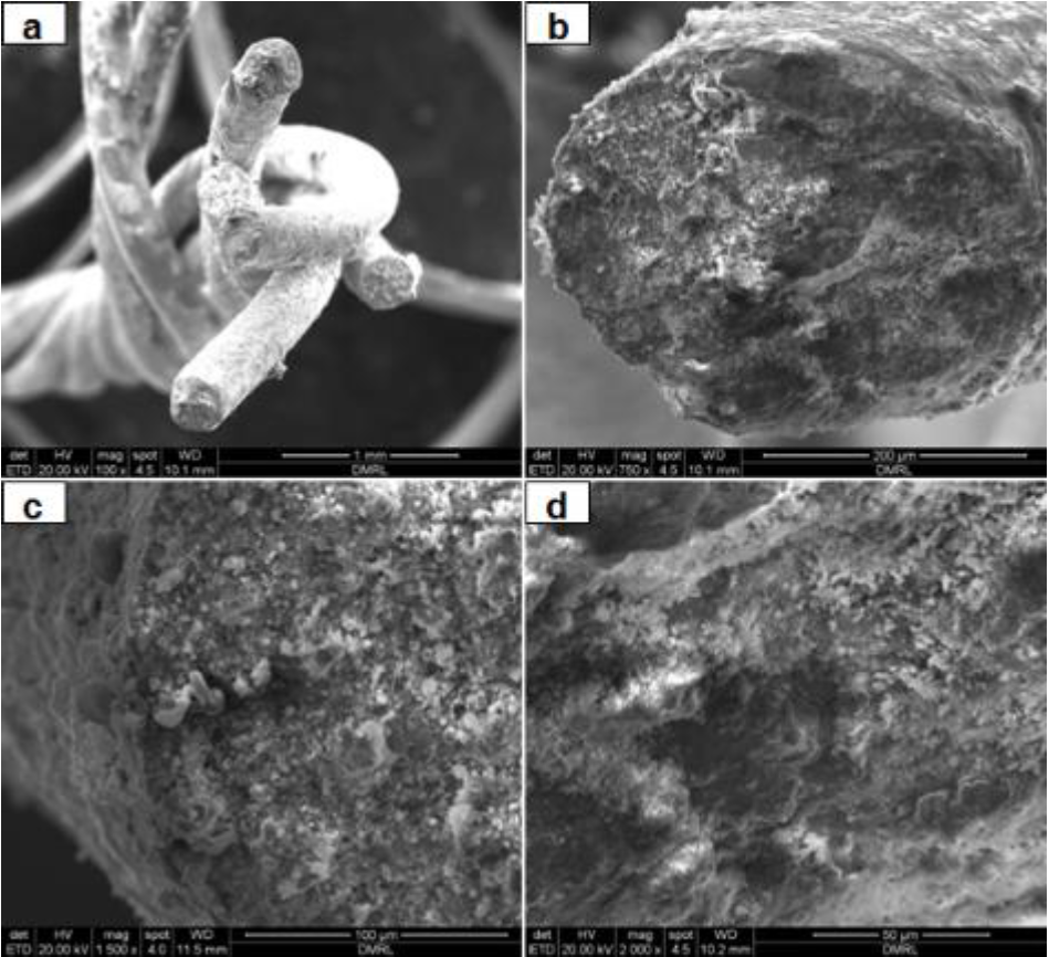
Fig. 6 SEM fractograohs of individual failed wire obtained at (a) Low magnification and (b-d) higth magnification show thick layer deposition of corrosión debris over the fracture Surface.
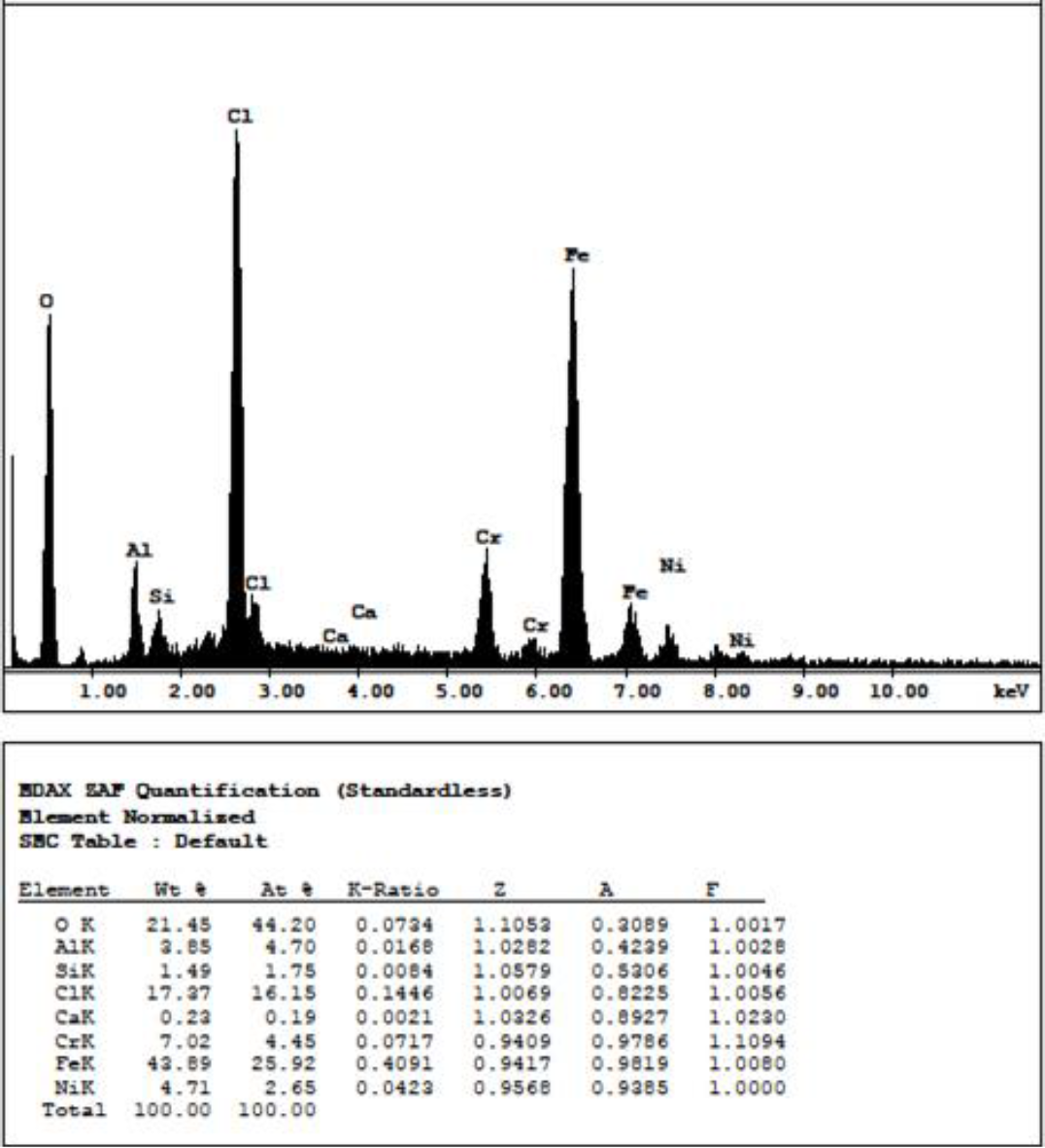
Fig. 7 EDS Spectrum taken from the fracture Surface of the failed individual wire exhibits presence of O and Cl in addition to matrix elements.
Tensile properties of failed, used (but not failed) and unused wire ropes are summarized in Table 2. Fascinatingly, the load bearing capacity of the failed wire has reduced to nearly 1/4 of the unused wire rope (Table 2). The used (but not failed) wire on the other hand also displays reduction in breaking load nearly 1/2 times than the unused wire rope. The ultímate tensile strength valúes of the wires reported in Table 2 also support the same. This also refleets that the properties of the rope have deteriorated significantly during service.
The results of the tensile tests of the failed and unused wires have been utilized to explain the oceurrence of typical fracture features of the failed wire rope. The fracture surfaces of tensile tested specimens of the failed and unused wires are shown in Figure 8 and The fíat fracture with no reduction in the cross sectional área is seen in the failed individual wire (Figure 8a). The fracture surface of the wire appears to be rough and clearly reveal the presence of intergranular fracture (Figure 8c-d). The failed wire clearly shows typical brittle fracture in spite of the presence of corrosive debris. Fracture surface of tensile tested wire of the failed rope displayed a thick metallic layer covered around the circumference of the failed wire.
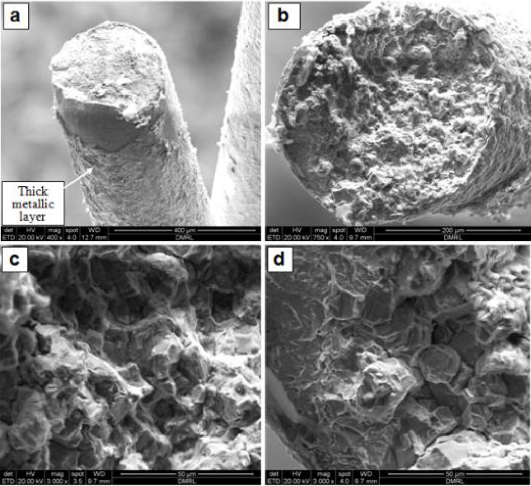
Fig. 8 SEM fractographs of tensile tested failed wire rope: (a) low magnification and (b-d) High magnification reveals flat fracture with intergranular mode of failure.
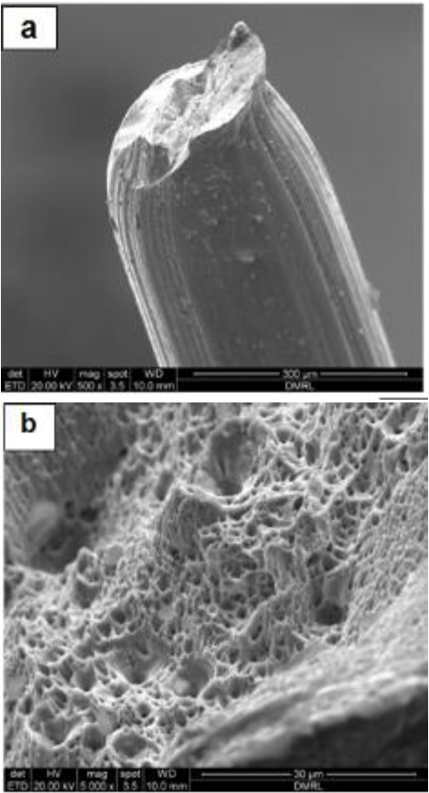
Fig. 9 SEM fractographs of tensile tested unused wire rope: (a) low magnification (b) high magnification showing considerable reduction in size with dimple mode of fracture.
However, a part of the thick layer of the individual wire has fallen away from cióse to tensile fracture during tensile deformation (Figure 8a).
Tensile tested fracture surfaces of the unused wires display entirely different features (Figure 9) than that of the failed wires in terms of mode of failure (Figure 8). The fracture surface of unused wire rope exhibits smooth surface finish around the rope outer surface (Figure 9a). The fracture features displays sufficient necking indicating typical ductile mode of failure (Figure 9b).
Unused wire rope has undergone significant necking before tensile failure and finally failed in ductile mode. This clearly suggests that the failed wire rope has slowly deteriorated during service and then suddenly failed with intergranular fracture mode. It appears that the crack propagated along the weak grain boundaries and finally failed in brittle mode of fracture (Figure 8).
When passive metáis such as the stainless steels corrode, the corrosión develops where passivity has been destroyed. If there are halogenides such as chlorides present in the environment, these can interact with passive film locally and break it by introducing small isolated spots (Bensalah, 2012; Leffler, 1998). This is also termed as pitting corrosión. This type of corrosión is likely due to chlorine-induced pitting of the stainless steel material from the chloride containing humid environment. The chlorides can then react with chromium to form soluble chromium chloride (CrCb) following 2Cr + 3Q2 = 2CrCl3 reaction. As a result, Cr at the grain boundaries is partly dissolved leaving only the corrosión prone iron (Tverberg, 2001). This also introduces depletion of Cr in neighboring área of the grain boundaries which are prone to fail in intergranular mode (Figure 5 and 8).
The occurrence of intergranular corrosión has also been reported even without the chromium carbide precipitates at the grain boundaries (Kodgire & Kodgire. 2013). This has been attributed to high energy associated with the grain boundaries which are preferentially corroded (become anode) due to their low electrode potential in comparison to grain interior. The present lanyard rope has also failed in intergranular mode due to the formation of CrCl3 in presence of humid environment.
As mentioned above, microstructure of the failed wire rope exhibits thin film at the grain boundaries consisting of O and Cl. It appears that the presence of both the high O and Cl at the grain boundaries can be due to corrosive atmosphere. The chlorine ions from the water content / vapours from humid atmosphere have initially reacted with chromium oxide passive film formed on the surface of the wire and then diffused within the material along the grain boundaries. The depletion of the Cr in vicinity of the grain boundaries supports the same (Figure 5). This has resulted in the failure of the wire rope in intergranular mode due to substantial weakening of grain boundaries.
4. CONCLUSIONS
The failed wire rope near the actual fracture región consists of large amount of oxygen and chlorine present in the initiation sites for cracks in the material.
The load bearing capacity of the failed wire rope strand has significantly reduced to nearly 1/4 times to that of the new unused wire rope in identical testing conditions.
Fracture surfaces of tensile tested failed and unused lanyard rope individual wires have shown intergranular and ductile dimple modes of fracture, respectively.
The lanyard wire rope has been exposed in corrosive atmosphere and failed in intergranular mode due to enrichment of O and Cl along the grain boundaries.
CONFLICT OF INTEREST
The autors have no conflicts of interest to declare.

