


 text new page (beta)
 English (pdf)
 Article in xml format
 Article references
 Send this article by e-mail
 Cited by SciELO
  Similars in
SciELO
Similars in
SciELO 
 Permalink
1. Introduction
Recently, strong interest has been shown in the application of metal matrix composites (MMCs) in the fields of aerospace and automotive with the purpose of enhancing mechanical and tribological properties of monolithic metals and alloys by introducing predominantly hard but brittle particles such as: Al2O3 , SiC, ZrO2 and B4C into the base alloys which has been reported by Bozic, Dimcic, Dimcic, Stasic, and Rajkovic (2010), Sajjadi, Ezatpour, and Beygi (2011), Kumar, Sharma, Panwar, and Pandey (2012), Mazahery, Shabani, Rahimipour, Tofigh, and Razavi (2012). Potential uses of these materials are numerous, especially in automotive area such as brake rotors and drums, cylinder liners, pistons, cylinder blocks, etc. in the studies reported by Su, Gao, Feng, and Lu (2012), Shabani and Mazahery (2012). Among the materials of mechanical and tribological importance, A356 (Al-7%Si-0.4%Mg) alloy has received considerable attention in casting processes due to its attractive castability, heat treatability and mechanical properties, Conley, Huang, Asada, and Akiba (2000), Dahle, Nogita, McDonald, Dinnis, and Lu (2005), Khan, Kutty, and Surappa (2006). Silicon carbide particles have become one of the popular reinforcing phases for many aluminum alloy-based metal matrix composites. They are hard and brittle ceramic particles with high strength, high modulus of elasticity, and high thermal and electrical resistance, which has been reported by Sajjadi, Torabi Parizi, Ezatpour, and Sedghi (2012). The fabrication methods of the composites can be categorized into three processes: solid-state methods, semi-solid-state methods and liquid-state methods. In the liquid metallurgy process, the particles are incorporated above the liquid temperature of the molten alloy (Stir casting), while in compocasting method; the particles are incorporated into the semi-solid slurry. Reddy (2003) demonstrated that the problem of unwettability between reinforcement and matrix of Al/SiCp composites can be effectively solved by adopting the compocasting technique, resulting in homogenous reinforcement distribution and enhanced mechanical and tribological properties of the composites. Although studies regarding the mechanical and tribological properties of particle reinforced aluminum matrix composites have been carried out, the effect of SiCp content on impact failure mechanisms as well as sliding wear mechanisms of A356/SiCp semi solid composites have not yet been well understood. Therefore, the aim of the present study is to determine the effect of SiCp weight fraction on the impact and wear properties and their corresponding mechanisms of semisolid A356/SiCp composites.
2. Experimental procedure
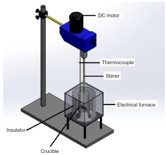
A356 Al-Si alloy was used as the matrix and 10, 20 and 25 wt% SiC particles in the range size of 32-80μm were employed as the reinforcement in fabrication of the composites. Chemical composition of A356 alloy is presented in Table 1. An electrical resistance furnace with a stirring mechanism (Fig. 1) was used for the dispersion of the ceramic particles into liquid aluminum. The SiCp were heated to a temperature of 900◦C within 2 h in a muffle furnace to increase their surface reactivity. The heat-treated particles were then added into the aluminum melt in semi-solid state (605 ± 5◦C) through the vortex, whereas slurry was stirring with speed of 600 rpm for 20 min. Then the composite melt was reheated to 670◦C and stirred again for 10 min to prevent the particles from settling. Finally the melt was poured into a cylindrical permanent mold at 630 ± 5◦C.
Table 1 Chemical composition of A356 aluminum alloy.
| Element | Si | Fe | Cu | Mn | Mg | Cr | Ni | Zn | Ti | Pb | Sn | Al |
| Wt% | 7.07 | 0.20 | 0.034 | 0.017 | 0.410 | 0.034 | 0.003 | 0.014 | 0.070 | 0.002 | 0.000 | Bal. |
The castings were machined to the required specimen dimensions for Charpy impact and dry sliding wear tests according to ASTM: E23 and ASTM: G99-05 (2010), respectively. The Charpy impact test was conducted using Zwick impact testing machine (D-7900) using a 15 J hammer to measure the total absorbed energy.
Sliding wear tests were conducted in pin-on-disk wear testing apparatus (Ducom, TR20-LE). The flat portion of 25 mm length and 6 mm diameter of the test pins specimen was loaded vertically on to the rotating steel disk of hardness 60 HRC with the help of stationary pin holder. A constant 30 mm track radius was used throughout the wear tests. The all wear tests were carried out under 10 N applied load and the sliding speed and sliding distance were maintained at 0.628 m/s and 1000 m respectively. Before the test, surface roughness of the disk was measured by the surface roughness tester (CS5000, Mitutoyo, Japan) and it was maintained between 0.02 and 0.06 μm. In addition the contact surfaces of the specimens prepared by grinding with 600-grit silicon carbide paper were subsequently cleaned with acetone and the measured roughness values lie in the range of 0.31-0.78 μm. The tests were carried out at ambient temperature without any lubrication. Since the wear testing was carried out on a microprocessor controlled machine, the height loss and frictional force were monitored simultaneously. The wear loss measured in microns was continuously monitored by the height loss of the specimen using a linear variable differential transformer (LVDT). The frictional force generated on the specimen was measured in Newton’s by using a frictional force sensor. For calculating the wear parameters, the height loss data was converted to volumetric loss by multiplying it with area of cross section of the test pin. The volumetric wear rate Wr (mm3 /km) was calculated using the expression:
For each condition, a set of three samples was tested in every experimental condition.
Hardness was determined using the Rockwell hardness test machine. The indenter used was a 1.56 mm steel ball, with a minimum and maximum load of 10 kg and 100 kg respectively. Prior to testing, the machine was calibrated using 101.2HRB standard block. Hardness test was conducted at three sections of the specimens. Samples for metallography were selected from the center of the castings and prepared through standard grinding procedures. The ground specimens were then subjected to a final polishing with colloidal silica suspension (5 μm). Samples were etched with 2% HF acid. Some samples were also deep-etched for 6 h in a solution of 5% HCl acid and 95% ethanol in order to reveal the three-dimensional morphology of the silicon phase. All the samples were analyzed using an optical microscope (Nikon-MIDROPHOT-FXL), scanning electron microscopy (Philips-XL 40). The fractured surfaces of impact test as well as the worn surface of the wear test specimens were examined using SEM.
3. Results and discussion
3.1. Microstructural analysis
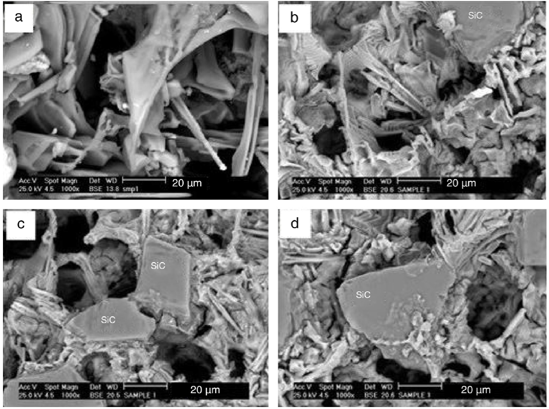
Optical micrographs of A356 alloy and MMCs reinforced with 10, 20 and 25 wt% SiCp are shown in Figure 2(a)-(d), respectively. Microstructural studies revealed a reasonably uniform distribution of SiCp with 10 wt% (Fig. 2(b)) and 20 wt% (Fig. 2(c)) SiCp without any particle macro-clusters. Ghandvar, Farahany, and Idris (2015), Hashim, Looney, and Hashmi (2001) have shown that distribution of SiCp influenced by good wett-ability of the silicon carbide by the molten metal and good interfacial bonding between SiCp and matrix material. However, some areas show agglomerates of SiCp in the alloy reinforced with 25 wt% SiCp as shown in Figure 2(d) (Mark A). Moreover, SiCp significantly refined the grains of Al matrix, as shown in Figure 2. The average grain size was about 100 μm in the alloy. It was about 50 μm in the 10 wt% composite. The grains were, respectively, reduced to 25 and 20 μm in 20 wt% and 25 wt% composites. OM observation also confirmed that most particles were segregated along grain boundaries in the micro-scale level. The grain refinement was mainly caused by particles’ obstacle to grain growth. Surappa (1997) reported that during their solidification, particles were mainly pushed to the intergranular regions, so particles limited the movement of Al grain boundaries and then retarded the grain growth. As an another indication of distribution of SiCp, cross sectional SEM microstructures of MMCs reinforced with 10, 20 and 25 wt% SiCp are presented in Figure 3(a-f) in low and high magnification. As shown, there is a uniform distribution of SiCp in MMCs with 10 (a, b) and 20wt%SiCp (c, d) and some agglomeration areas of SiCp with 25 wt% of reinforcement particles (e, f).
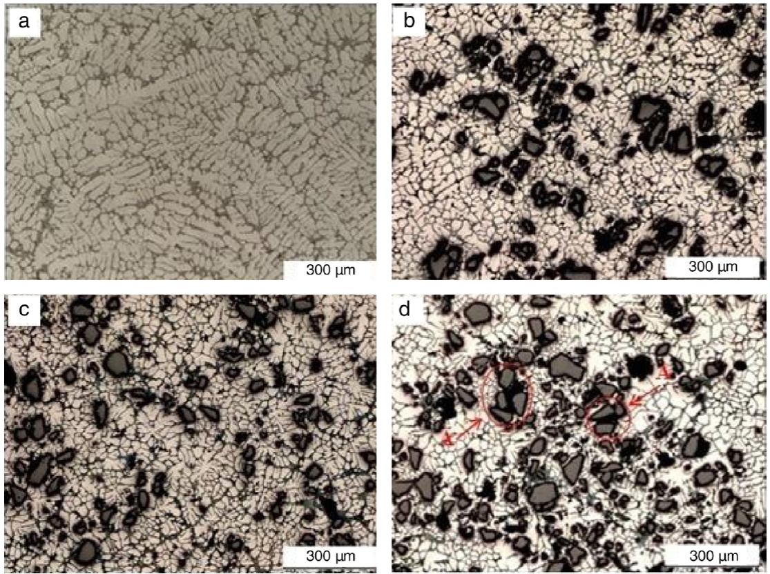
Fig. 2 Optical micrographs showing the microstructure of (a) A356 alloy and MMCs containing, (b) 10, (c) 20, (d) 25 wt% SiCp.
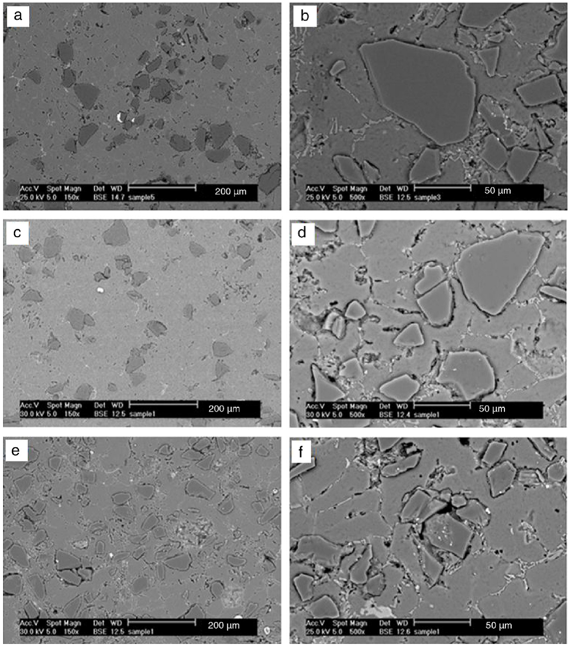
Fig. 3 Cross sectional SEM microstructures of MMCs reinforced with 10 (a, b), 20 (c, d) and 25 wt% SiCp (e, f) in low (left) and high (right) magnification.
Figure 4(a)-(d) shows high magnification SEM images of eutectic Si in the A356 alloy and in the vicinity of SiCp in MMCs reinforced with 10, 20% and 25 wt% SiCp, respectively. According to Figure 4(a), acicular silicon can be seen in interdendritic regions of A356 alloy. However, there is a significant refinement in the size of eutectic silicon particles with an increase in SiCp weight fraction to 10 and 20 wt% SiCp as shown in Figure 4(b) and (c), respectively, and the largest refining effect of eutectic silicon (due to more incorporation of SiCp) is achieved when 25 wt% SiCp is added into the melt (Fig. 4d). Nagarajan, Dutta, and Surrapa (1999), Lashgari, Zangeneh, Shahmir, Saghafi, and Emamy (2010) reported that due to the particle pushing phenomena, SiCp were rejected by the solidification front and finally trapped in the interdendritic zones. As a result, SiCp act as a physical barrier for eutectic silicon growth during solidification and leads to refinement of eutectic Si.
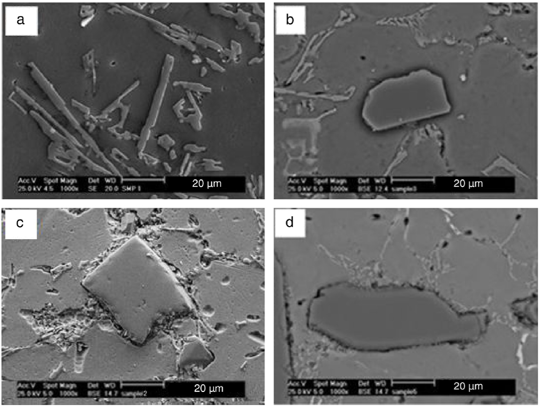
Fig. 4 SEM micrographs showing the size of interdendritic eutectic silicon in (a) A356 alloy and MMCs containing, (b) 10, (c) 20, (d) 25 wt% SiCp.
In addition to the refinement of silicon, SiCp also affect the morphology of eutectic silicon and the aspect ratio of the eutectic silicon decreases with increasing SiCp content in the MMCs. It is difficult to distinguish the changes in the morphology of eutectic silicon due to the effect of SiCp in Figure 4. Thus, samples with different SiCp contents were deeply etched to remove the Al matrix, and three-dimensional structures of the eutectic silicon phase were analyzed with SEM. The microstructures of the eutectic phase of A356 alloy and MMCs are shown in Figure 5 (a-d). The figures display the structural differences between A356/SiCp MMC with different SiCp contents. In A356 alloy, the eutectic silicon structure consists of large silicon plates, as shown in Figure 5a. In the MMC containing 10 wt% SiCp, the eutectic silicon structure was observed in the form of short silicon plates (Fig. 5b), whereas the needle shape eutectic silicon are found to have formed around the SiCp in the MMC containing 20 wt% SiCp (Fig. 5c). In addition, morphology of eutectic silicon also changes from needle shape to equiaxed in the presence of 25 wt% SiCp (Fig. 5d). The result clearly indicates that the eutectic silicon has undergone a transition from a plate-like to equiaxed morphology with increasing weight fraction of SiCp in the matrix. Another reason for modifications in the size and shape of eutectic silicon is presence of some eutectic silicon on the surface of SiCp in Figure 5d, which indicates heterogeneous nucleation of eutectic silicon on SiCp. In addition, presence of SiCp can also affect the thermal field (because of thermal mismatch between the matrix and SiCp) and solute field(by interrupting diffusion of solute silicon) locally and thereby cause refinement of silicon, (Nagarajan et al., 1999). As expected an increase in the weight fraction of SiCp promotes further nucleation of silicon on SiCp and causes an increased refinement of silicon (Fig. 5d). Silicon morphology is modified also by introducing of zircon sand particles to Al alloy. Kaur and Pandey (2010) have reported that zircon sand particles provide nucleation site for solidification of Si and changes the morphology of silicon particles from long thin needle shape to globular. In fact, the localized cooling effect produced by zircon sand particle around its vicinity led to such type of morphological changes. The particles get embedded in the molten alloy and extract heat at higher rates from the surrounding melt, which give rise to localized rapid cooling effect during solidification. Because of this phenomenon, the formation of small globular Si morphology in vicinity of zircon sand particle was observed. Similarly, Kaur, Anant, and Pandey (2011), found structural variation on transition of silicon phase morphology to spherical shape in near eutectic Al-Si alloy with addition of Sn. When the SiCp is introduced into the melt, due to difference in the temperature of SiCp and molten metal, a thermal gradient has been generated which give rise to the splat quenching in the region around its deposition leading to generation of small silicon globules around the SiCp.
3.2. Hardness
The hardness value increases as the percentage SiCp addition increases in the alloy (Fig. 6). This is due to increase in the percentage of the hard and brittle phase of the ceramics in the alloy. The silicon carbide addition reinforced the alloy by increasing the dislocation density at the particles-matrix interfaces. Amirkhanlou and Niroumand (2012) proposed that the differences in the coefficient of thermal expansion (CTE) between the hard and brittle reinforcing particles and the soft and ductile metal matrix result in the elastic and plastic incompatibility between the matrix and the reinforcement. Thus improves the mechanical properties. Furthermore, Panwar and Pandey (2013) reported that the hardness values of composite materials are affected by distribution of ceramic particles inside the matrix alloy and the surface bonding in interface of matrix and reinforcement. The homogeneous distribution of ceramic particles in the matrix and presence of good interfacial bonding in interface give rise to hardness value of MMCs.
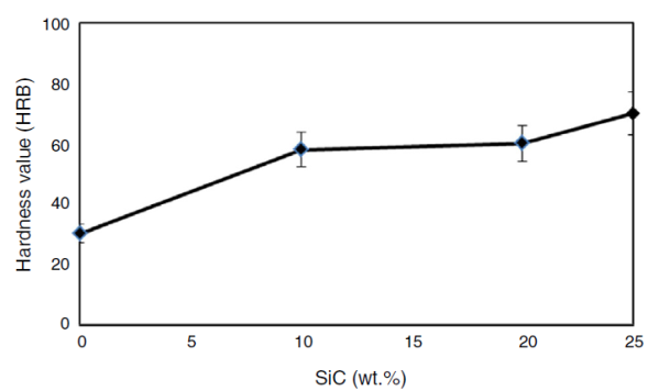
3.3. Analysis of impact behavior
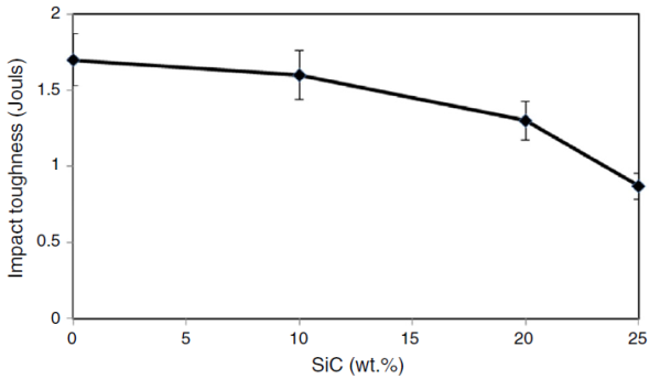
The results of the impact toughness of the fabricated MMCs as a function of weight percentage of SiCp are shown in Figure 7. It can be seen that although increasing the SiCp content in the matrix alloy leads to the refinement and modification of the eutectic silicon, the impact toughness decreased as the content of SiCp addition increased. The brittle nature of the reinforcing materials (SiCp) plays a significant role in degrading the impact toughness of the composites. Therefore, the lower impact toughness of A356/25%SiCp MMCs (0.87 J) compared to other alloys can be attributed to the presence of more brittle SiCp in the matrix, which may act as stress concentration areas. Furthermore, the heterogeneous dispersion of SiCp in A356/25wt%SiCp composite resulted in the formation of clusters. The clustered particles were easily separated under the impact loading. When this failure combines with the failures of debonding in the particle-matrix interface, the impact toughness of composites decreases drastically. Since A356 alloy and MMC with 10% SiCp have the highest impact energy (1.7 J, 1.6 J), respectively, compared to other fabricated composites, it is manifest that they are the toughest of them all.
3.3.1. Fracture analysis
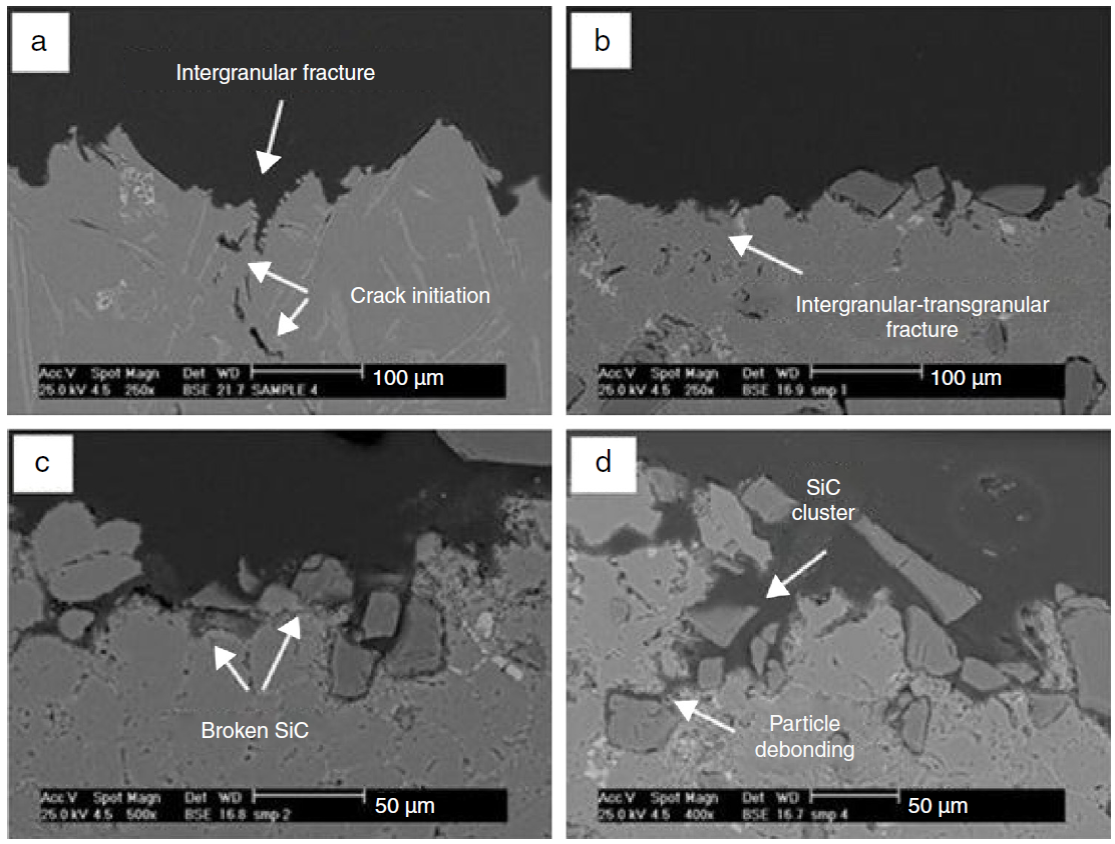
The fractured surface of the impact testing samples with its longitudinally sectioned profile was investigated to examine the type of failure under SEM which are presented in Figures 8 and 9, respectively. Elsebaie, Samuel, and Samuel (2011) observed that the fracture mechanism of the Al-Si systems consists of two main stages, initiation of microcracks and propagation of crack to fracture. The coarse flake or needle-like Si are sites for high stress concentration and initiation of microcracks as shown in Figures 8a and 9a. Figure 8a shows the cleavage fracture surface of the A356 alloy. The microcrack initiated due to fracture of the coarse Si phase as shown in Figure 9a. The crack propagated to the adjacent microcracks of the fractured Si particles forming a principal crack, Elsebaie et al. (2011). The crack then propagates through the cleavage of coarse Si as shown in Figure 8a (point A) indicating mainly brittle intergranular fracture mode (Fig. 9a). Figure 8b shows the fractured surface of the 10 wt% SiCp composite reinforced A356 alloy. Cleavage fracture of the fractured coarse eutectic silicon (Mark A) was observed along with dimple structure (point B) indicating ductile fracture. In fact, existence of dimples is due to refinement of some eutectic silicon with increasing the SiCp content to 10%. Therefore, main crack crosses a two-phase zone in eutectic Al-Si. As a result, A356/10wt%SiCp composite failed in transgranular-intergranular mode (Fig. 9b), Casari, Fortini, and Merlin (2013). Increasing of SiCp content changes the fracture behavior of composite samples significantly. Figure 8c shows the fractured surface of 20 wt% SiCp composite sample. The distribution of SiCp appears to be reasonably homogeneous without clustering or agglomeration. Dimples can be seen on the fractured surface (mark B) as a result of refinement of eutectic silicon. There is no void formation or debonding between matrix and particle reinforcements interface, which indicates a good matrix-reinforcement interfacial bonding. Although there is no debonding, the particle cracking is clearly seen (Fig. 9c). Therefore, the failure mode is dominated by the particle cracking where fracture of particles takes place when the interface is stronger than the particles. However, with increasing weight percentage of SiCp to 25%, it is more difficult to obtain a homogeneous particle distribution which result in the formation of clusters, which make it prone to crack formation and propagation (Fig. 8d) - (mark C). Furthermore, it can be seen that the void around the particles is related to the inter-facial debonding and the failure phenomena indicates weak particle-matrix interface. It has been observed in Figure 9d, that both clusters of particles and weak particle-matrix bonding have caused preferential directions for crack growth mechanism. An explanation for this failure mechanism is that in regions of clustering or agglomeration and decohesion of interface, the short interparticle distance facilitates linkage between neighboring voids and microscopic cracks as a direct result of decreased propagation distances between SiCp. These failure mechanisms had a significant effect on decreasing the impact toughness of composites (Fig. 7).
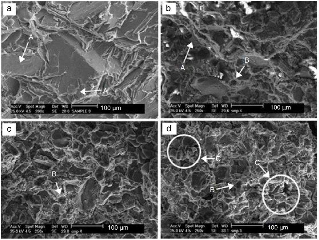
Fig. 8 Fracture surfaces of (a) A356 alloy and MMCs containing, (b) 10, (c) 20, (d) 25 wt% SiCp samples failed in impact test.
3.4. Analysis of wear behavior
Figure 10 shows the relationship between the effect of wt% of SiCp on the wear resistance behavior of A356/SiCp composites at fixed load of 10 N and sliding distance of 1000 m in terms of wear rate. It can be seen that the highest wear rate belonged to base A356 alloy and for reinforced alloys, wear rate is significantly decreasing with increasing of wt% of SiCp addition to 20%. In fact, the addition of reinforcement improves the critical transition values of applied load and wear resistance compared with the corresponding matrix alloy. It is clear that the unreinforced matrix alloy wear more rapidly than the reinforced composite materials since it is subjected to asperities of harder material (hardened steel disk). In addition, tendency of acicular eutectic silicon (Fig. 4(a)) to crack during the wear test is another reason for increasing the wear of A356 alloy. Bermudez et al. (2001) indicated that the wear rate is inversely proportional to the hardness of alloys. Increase in hardness results in improvement of wear and seizure resistance of materials. Among many ceramic materials, SiC and Al2 O3 are widely in use, due to their favorable combination of density, hardness and cost effectiveness. When these reinforcements are combined with aluminum, the resulting material exhibits significant increase in its elastic modulus, hardness, strength and wear resistance, Veeresh Kumar, Rao, and Selvaraj (2012). As mentioned earlier, the addition of hard ceramic SiCp increases the hardness of A356 alloy (Fig. 6). In the case of A356 alloy, the depth of penetration is governed by the hardness of the specimen surface and the applied load. But, in the case of MMCs, the depth of penetration by the harder asperities of hardened steel disk is primarily governed by the protruded hard ceramic reinforcement. Thus, the major portion of the applied load is carried by SiCp. As a result, the sticking tendency due to softening of surface material with the counter surface reduces in case of composite as compared to the alloy. According to Shabani and Mazahery (2012), the role of the reinforcement particles is to support the contact stresses preventing high plastic deformation and abrasion between the contact surfaces and hence reduce the amount of worn material. Another reason for decreasing the wear rate of fabricated composites with increasing the SiCp content is also associated with the partial refinement of coarse eutectic silicon as a result of increased SiCp weight fraction. In fact, reduced tendency of eutectic silicon to crack in this composite is effective in resisting wear, leading to decreased wear rate. However, increasing the SiCp content to 25 wt%, provokes clustering of the particles during the fabrication of the composite, therefore in spite of increasing the hardness and more refinement in the size and morphology of eutectic silicon, the wear rate of A356/25wt%SiCp, increased but not as much as base A356 alloy (Fig. 10). The strength of particles/matrix interface is very important parameter since interfaces could be relatively weak due to interfacial reaction and poor wettability. In A356/25wt%SiCp, since particles associated with such clusters are only loosely bonded to the matrix, they are easily pulled out of the matrix during wear and soft aluminum matrix will be subjected to asperities of hardened steel disk. In addition, hard pulled out particles take part in three-body abrasion, thus increasing the wear of the specimen (Fig. 10). Therefore, it can be concluded that if the reinforcement is well bonded to the matrix (A356/xSiCp(x = 10, 20 wt%)), the wear resistance of composite increases continuously with increasing the weight fraction of reinforcement. In contrast, if the reinforcement is not well bonded to the matrix (A356/25wt%SiCp), the wear resistance of the composite increases up to a critical amount of the reinforcement and thereafter starts to decrease.
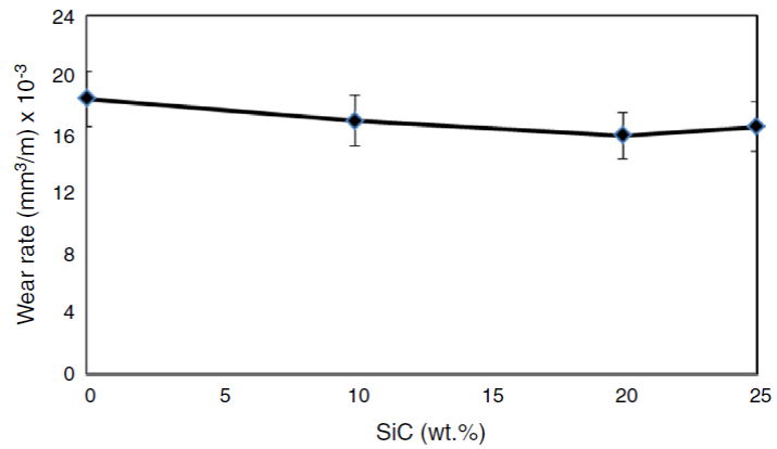
Figure 11 shows the friction coefficient values of the matrix alloy and MMCs containing different percentages of SiCp. The friction coefficient values of the matrix alloy and composite materials were in expected range for light metals in dry sliding conditions. As shown in Figure 11, the friction coefficient of MMCs are higher than those for the A356 alloy which corresponds to lower value of the wear rate compared with the matrix alloy (Fig. 10). It has been mentioned that the hard SiCp penetrate deep into the counter surface leading to formation of microchips from counter surface. As a result, greater amount of frictional force is required for sliding of composite over the counter surface, Ghandvar, Farahany, and Idris (2017). Therefore, as the SiCp content increases, the number of SiCp penetrating to the counter surface increases and thus the coefficient of friction in composites increases with increase in SiCp content. Furthermore, during the sliding, the pins of matrix alloy deform plastically during sliding, which result in low friction coefficient. The higher coefficients of friction in the case of composites containing hard SiCp are due to the formation of tribofilm at the interface between pin and disk. If the effective load on the individual particle is above its flexural strength, the particles get fractured. Parts of the removed SiCp are entrapped between two partners, i.e. asperities of softer material of pin and asperities of harder material (hardened steel disk), possibly leading to three-body abrasion; the result will then be more surface roughness between contacting surfaces and increase of coefficient of friction, which has been reported by Vencl et al. (2010). The increase of the friction coefficient with the amount of reinforcement particles is ascribed to the fact that the amount of protruded particles increases during wear occupying larger area of pin surface. At the same time, one part of protruded particles are torn away from the matrix and fractured into fragmented pieces. In this situation, the contact between the hard particles and the counter body material is resulting in higher coefficient of friction. However, in A356/25wt%SiC, in addition to the protruded SiC particles, poor interfacial bonding between the matrix and SiCp as well as particle clustering, which leads to particle transferring from the matrix to the pin and disk interface during sliding, leads to coefficient of friction to be increased.
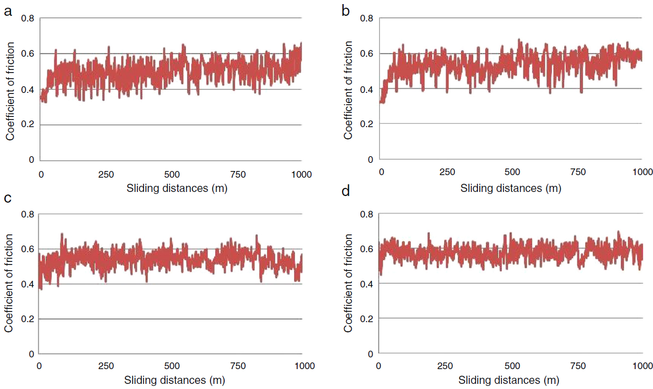
Fig. 11 Friction coefficient (μ) of (a) A356 alloy and MMCs fabricated with different SiC contents, (b) 10% SiC, (c) 20% SiC, (d) 25% SiC under 10 N applied load.
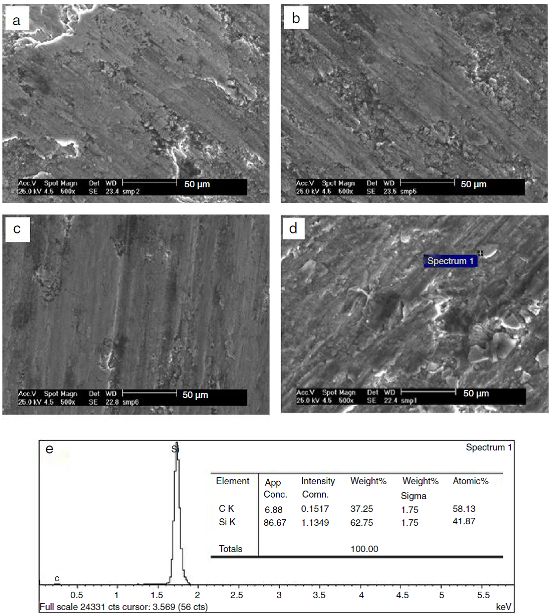
Figure 12 shows the worn surfaces of A356 alloy and different fabricated composites which were examined under SEM. Figure 12(a) shows the worn surface of A356 alloy. The A356 matrix alloy is much softer than the counter body material, and during sliding the counter body penetrates into the matrix alloy, producing deep grooves and causing extensive plastic deformation and abrasion of the surface, which results in great material loss and significant wear rate (Fig. 10). The worn surfaces also contain the evidence of adhesive wear in the form of adhesive pits due to the delamination of surface. On the other hand, the large scale of the matrix alloy is transferred to the counter body. The flow of materials along the sliding direction, the generation of cavities due to the delamination of surface materials and tearing of surface material are also noted in this figure. Another reason for significant material removal of A356 alloy is debris of coarse eutectic silicon particles which are cracked during the wear test and adversely affect the soft matrix leading to substantial wear. Figure 12(b, c) shows the worn surfaces of A356/SiCp composites with 10 and 20 wt% SiCp, respectively. Formation of continuous wear grooves with decreasing in depth and width of the grooves and pits on the worn surfaces and formation of parallel lips along the continuous groove marking can be observed on the worn surfaces compared to worn surface of A356 alloy. In fact, enhanced amount of SiCp prevents severe wear by protecting the soft matrix and improving wear resistance. In addition, since the particles remain well bonded with the matrix during sliding in A356/SiCp composites with 10 and 20 wt% SiCp, the aluminum matrix that surrounds the particulates will be worn away, and essentially all contact will be between the reinforcing particles and the counter body. Furthermore, increasing the SiCp content leads to modification of eutectic silicon in the fabricated composites, the tendency of the eutectic silicon to fracture during sliding and consequently crack formation is decreased. However, in spite of high hardness and more refined eutectic silicon in A356/25wt%SiCp compared to other fabricated composited sporadic deep caverns formed by the pull-out of SiCp from the matrix indicate particle clustering and relatively weak interfacial bonding between the aluminum matrix and SiCp (Fig. 12 (d)). These SiCp, fractured into fragmented pieces are entrapped between the pin and the counter body, and together with the protruded SiCp from the matrix act as abrasives, enhance material removal from the contact surfaces and decrease the wear resistance. Furthermore, the wear track widths of A356 alloy and fabricated composites is reduced in the worn surfaces with increased content of SiCp, i.e.; from 26 m in A356 alloy to 19 and 15 m in MMCs reinforced with 10 and 20 wt% SiCp, respectively, indicating lower material removal in comparison with A356 matrix alloy as evidenced in SEM photograph shown in Figure 13(a-c). However, in MMCs with 25 wt% SiCp (Fig. 13d), the wear widths of the worn surface increase to 22 m, which is due to abrasive action of fragmented or protruded SiCp. The EDS result (Fig. 13e) confirms the presence of SiCp on the worn surface of MMCs with 25 wt% SiCp. In fact, defects such as clusters of reinforcement particles impair the mechanical and tribological properties of the composite. Differences in particle sizes, densities, geometries, flow or development of an electrical charge all contribute to particle agglomeration. The uniformity in distribution of particles within the sample is a microstructural feature which determines the in-service properties of particulate AMCs.
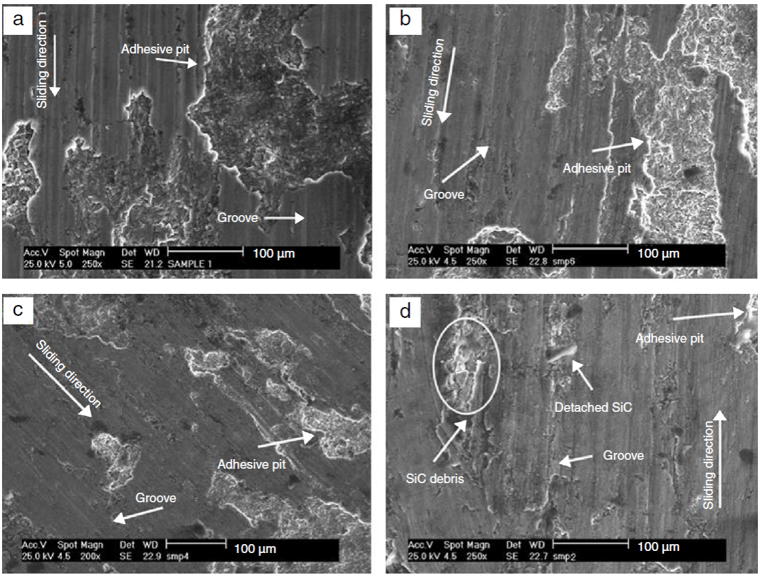
Fig. 12 Comparison of SEM worn surface images of (a) A356 alloy and MMCs fabricated with different SiC contents, (b) 10% SiC, (c) 20% SiC, (d) 25% SiC under 10 N applied load.
4. Conclusion
A356/xSiCp composites were successfully fabricated by semisolid stirring technique. The effect of SiCp content on microstructure, impact toughness as well as wear properties of the composites were examined. The main conclusions can be drawn as follows:
The particle distributions were fairly uniform in A356/xSiCp (x = 10, 20 wt%) composites, however, increasing the particles content to 25% leads to agglomeration and debonding of SiCp in the matrix alloy.
During solidification of A356/SiCp composites, SiCp are rejected into the interdendritic regions and act as a barrier for growth of eutectic silicon leading to a size refinement. Heterogeneous nucleation of eutectic silicon on SiCp is another reason for eutectic silicon refinement. Furthermore, morphology of eutectic silicon also changes from plate shape to equiaxed in the presence of SiCp (from 0 to 25%wtSiCp).
The hardness of tested materials increases with the increase of SiCp amount and the composite with 25 wt% of SiC reinforcement owns the highest hardness value.
The presence of brittle SiCp as reinforcements in a ductile matrix of A356 alloys decreased the impact toughness of fabricated composites and impact toughness significantly reduced with increasing the SiCp weight fraction. The impact behavior of composites was affected by particle cracking, clustering and debonding of SiCp.
The addition of reinforcement improves the wear resistance of fabricated composites due to increase of hardness and refinement of eutectic silicon compared with the corresponding matrix alloy. However, the increase of SiCp weight fraction to 25% can provoke clustering of the particles and consequently poor bonding between matrix and particles and decreasing the wear resistance of the composite. The wear mechanism of A356 alloy changed from a combination of severe to mild abrasion and adhesion wear in A356/20wt%SiCp composite. However, severe abrasion is the dominant wear mechanism after increasing the SiCp content to 25 wt%.

