


 nueva página del texto (beta)
 Inglés (pdf)
 Artículo en XML
 Referencias del artículo
 Enviar artículo por email
 Citado por SciELO
  Similares en
SciELO
Similares en
SciELO 
 Permalink
1. Introduction
This work presents a complete system for modeling the appearance and expressions of a virtual character based on the facial movement of a human subject. Stereo web-cameras perform marker based motion capture to obtain head rigid motion and the non-rigid motion of expressions. Tracked 3-D points are then mapped onto a 3-D face model with a virtual muscle animation system. Muscle inverse kinematics (IK) updates muscle contraction parameters based on marker motion to create the character’s expression performance.
A design goal was to allow any 3-D human face model to be used with any set of face motion capture data. This gives the ability to retrofit existing models. It also allows the system to drive a wide variety of face models that do not have to be human in nature. To do this, mapping of markers into a new face space was performed with radial basis functions (RBFs), where the required correspondences between markers and vertices of the mesh were predefined. This procedure takes only a few minutes and need only be done once for a certain marker set and face model, since the marker template, marker correspondences, and RBF mapping coefficients can be saved for future use.
The advantages of the system are multiple and are with existing systems, described in Section 2 and compared in Section 8. Overall, our system is low-cost as only standard hardware and cameras are required, with no need for special lighting, making the system available to a wide range of users and situations. It has a low set-up time with no need for long and repetitive training when users are changed. The system is robust under differing conditions, i.e. illumination, facial hair, skin tone. Despite using off-the-shelf self-made markers, it generates less noise in tracked points and is more reliable than many markerless approaches including those tried in Section 8.
Our animation model uses abstract muscle definition, therefore it provides a useful constraint on possible face expressions and this can help deal with noise in the motion capture data. Also, the abstract muscle definition allows mapping and animation between different face models, offering a straightforward way to animate a wide number of 3-D models with the same animation data - e.g. capturing a human face performance and applying it to a virtual anthropomorphic animal face.
We also combine a reduced character creation time by using virtual muscles, a novel way of combining marker tracking with a face animation system using muscle inverse kinematics (IK) and its low cost hardware requirements, capable of running on standard hardware. Our framework requires only a standard PC with web-cameras and colored markers (self-adhesive labels), available from stationery suppliers. This fulfils a major design goal to make the system suitable for end-user environments. As an extension, provided minimal changes, a Microsoft Kinetic could be used to extract depth and marker positions that could be mapped to our current setup instead of stereo cameras.
Marker based motion capture was chosen for its ease of motion tracking, dealing with noisy environments and providing low computational costs and a simple algorithmic formulation over markerless based approaches. A pair of stereo cameras was chosen over a single camera approach to accurately estimate 3-D marker positions. Inverse kinematics is widely used in robotics as a tool for animating articulated figures and to reduce the amount of data needed to specify an animation frame (Welman, 1993). We focus on the Jacobian transpose approach to inverse kinematics, Baxter (2000), for its computational tractability and ease of implementation. This research aims to create a complete system for expression modeling, to investigate the expressive power of a minimal set of markers, and to pursue an animation approach that is model based instead of image based.
It is hypothesized that given a suitably complex animation system a minimal number of input marker positions are needed to create realistic expressions. This assumes that noise has minimal influence on accuracy and can be subsumed by the animation system. This work parallels Choe, Lee, and Ko (2001), however their approach required face and motion data from the same test subject. In our system radial basis functions (RBFs) were used to align and pair marker data with corresponding points on an arbitrary 3-D human face model. This decouples the subject’s face shape from the shape of the 3-D model. In addition it was found that the 3D model’s shape differed noticeably from the actual subject’s marker locations. Therefore using RBFs was important for obtaining visually realistic results.
This article is structured as follows: firstly, related work is presented in Section 2 followed by a design overview in Section 3, listing the core components of the system. The 3D face animation system is described in Section 4. Then a description of the marker tracking process is described in Section 5. Marker mapping between tracked points and a 3D face model is then described in Section 6. This includes a novel way of creating a personalized face model from 3D reconstruction data. A novel method to drive face animation through a general muscle inverse kinematics framework is then given in Section 7. A selection of results and analysis of system performance explore the effectiveness of the generated expressions in Section 9. Then, the systems ability to recognize expressions is tested in Section 10. Finally, the conclusion and future work are presented.
2. Related work
There are a number of facial expression capture techniques that can be grouped into either marker or markerless approaches. Marker based approaches have been the mainstay of industry applications, due to their reliability in tracking and low computational cost. On the other hand, marker based approaches are algorithmic in nature and offer the possibility of freeing a performer from requiring a lengthy setup procedure. Because of this, a great deal of research has been placed on developing them. Furthermore, (facial) motion capture’s importance for animation has resulted in it becoming an integral component of commercial 3-D modeling packages such as Maya (2013) and 3Ds (2013).
Expression retargeting refers to techniques that take the expressive performance of one subject and retarget it onto a 3-D model of different proportions. This is useful for projects that use fantastical creatures as avatars that have anthropomorphic facial expressions. A common approach is to use a set of expression base shapes, often called “blend-shapes”, which are blended together and selected based on retargeted motion data, e.g. Liu, Ma, Chang, Wang, and Debevec (2011) and Weise, Bouaziz, Li, and Pauly (2011a). As another example, the work of Stoiber, Seguier, and Breton (2010) used a database of 2-D face motion to create a set of “bases” - our approach is computationally simpler and more accessible, but our 3-D expression data could be used in such a frame work to give more depth information.
Famous examples of marker based motion capture can be found in the movies Polar Express (the facial expression capture of Tom Hanks’ character), and in Avatar, where a number of painted markers were tracked by miniature cameras mounted onto the actors. Interestingly, the facial animation for the popular character Gollum of the Lord of the Rings trilogy, was artist created and only inspired by the facial performance of actor Andy Serkis (Gollum, 2013).
One example of a marker based approach is the Light Stage, used in such movies as Spiderman 2. The basic approach, as described in (Hawkins et al., 2004), used 30 strobe lights, placed in a moveable semicircular arc, which were used to capture the reflectance properties of an actor’s face. Additionally, 3D data of the actor’s face shape was recorded under different expressions. Marker motion capture was then used to drive a performance which blends and warps the different expressions together.
The Playable Universal Capture system, described in Borshukov, Montgomery, and Werner (2006), presents another technique for facial animation. A high-resolution scan of an actor’s face was taken, which was then mapped and animated using separately recorded marker based motion capture data. Face texture was acquired as a video stream and mapped to the 3-D model, synchronized to the motion capture performance. A number of facial expression clips can be smoothly cycled between, but overall this is not an approach whose motion data can be easily retargeted to other face models.
A few examples of successful markerless face motion capture approaches are Mova (2004), a markerless facial expression capture solution that requires the application of special phosphorescent make-up. The work of Chai, Xiao, and Hodgins (2003), where a database of motion capture was correlated with tracked face feature points to create new performances. And lastly, the well known Active Appearance Model (AAM) (Cootes, Edwards, & Taylor, 1998; Xiao, Baker, Matthews, & Kanade, 2004) approach. Here, texture and shape variation were modeled through prior learning on a database. Expression tracking is made possible if sets of expressions are also annotated in the database. However, the computational complexity of the approach, along with the training stage, are much higher than the approach presented here. Also, the proportions of unseen faces must successfully lie within the expression space constructed from the database for the system to work properly - our system is not restricted in this sense.
The MirrorMoCap system by Lin and Ouhyoung (Lin & Ouhyoung, 2005) uses more than 300 fluorescent markers and a mirror system to accurately track the shape of the face. The use of the mirror system allows a wider angle of the face to be captured with a single camera. The system operates at sub-video frame rates, and requires specialised illumination and mirror equipment setup.
Sifakis, Neverov, and Fedkiw (2005) presented a facial animation method using inverse kinematics similar to our work here. However their system does not deal with real-time expression information from cameras. Their system also requires a much higher number of data points on the face model and is designed for use with professional motion capture data.
The Faceshift system by Weise, Bouaziz, Li, and Pauly (2011b) uses a depth and texture sensor (e.g. Kinect) to enable facial expression control of a digital avatar in real-time. The system is non-intrusive, requiring no markers to be placed on the subject, but requires training to model a subject’s expressions. The training step adapts a user’s expressions to a generic blendshape model and is performed off-line prior to recording the desired performance. After training, the system is capable of reconstructing fine details of an expression, such as the lips and eyebrow shape and movement. The system is available as a commercial product1 with a subscription fee of $1500 USD per year.
We obtained a trial version of the product to evaluate its effectiveness. Training requires the user to perform 21 predefined facial expressions, namely, neutral, open mouth, smile, brows down, brows up, sneer, jaw left, jaw right, jaw front, mouth left, mouth right, dimple, chin raised, kiss, lip funnel, frown, ‘M’, teeth shown, puff, chew, lip down. The user is required to rotate the head to the left and right during the expression recording to obtain data for the side of the face model. During our testing, we found that a number of expressions such as ‘lip down’ were difficult to perform as they require unnatural muscle movements. However the developers mention the system will have more natural expressions to train in future versions.
Overall the training took between 15 and 30 min. We also found that it was sometimes hard to properly replicate some of the 21 predefined facial expressions. This could lead to badly trained and represented 3-D face, with far from satisfactory results. With a properly trained system, we replicated the six universal expressions. We observed that the Faceshift system is in general fluid, responsive and capable to track some expressions. The user-specific 3-D representation did bear some resemblance to the original and the replicated expressions did somehow relate to the original expressions. Faceshift still had trouble with correctly identifying facial hair and fine movement of muscles and requires training for each new user which contradicts the goal of our system i.e. a universal user-independent system requiring no training.
Choe et al. (2001) models the face using 13 different facial muscles along with a skin deformation model using a finite element model (FEM) for the skin surface. Facial performance capture is accomplished by three calibrated and synchronized cameras observing 24 retro-reflective markers glued to the face. The steepest descent method is used to find muscle actuation parameters that best fit the marker positions. Similar to our work, expression retargeting is done using the muscle parameters from observed expressions to animate another face.
A common feature amongst marker based systems is a high hardware requirement and lengthy setup procedure. We instead focus on what can be done with stereo web-cameras and cheap and easily applied adhesive stickers. In addition, once motion capture data is acquired it generally needs to be cleaned up or manipulated before it is in a useable state. We look at removing this difficulty by using an RBF retargeting approach, projecting motion vectors onto virtual muscle vectors to constrain movements to valid ones. By automating our approach we also want to remove the high learning curve of the professional 3-D modeling software environments for facial expression creation.
Regarding the applications of this technology, the investigation of mood and emotions dates back to the seminal work of Ekman and Friesen (1971). With the emergence of social interfaces and virtual worlds there has been a renewed interest in ways to directly input or modify content based on a users’ instantaneous mood or emotion (Kaliouby & Robinson, 2004). The exploration of emotions and moods in HCI has led to applications such as the popular MobiMood, where users convey their mood status via short typed messages. Such applications have a strong appeal on mobile phones and increasing computing power and 3-D display capabilities (Tegra, 2013) should allow a more direct and automated way to convey mood and emotions. As such, our presented work aligns well with the current trends and needs within the multi-media domain for the pursuit of the better understanding, generation and detection of the information expressed by a face (Rachuri et al., 2010).
This research expands and improves on that presented in Woodward, Delmas, Gimel’farb, and Márquez (2007).
3. System design
The system comprises three modules: facial animation, marker tracking, and marker to model assignment which links the other two modules. Each module is described in brief here and then elaborated upon in their relevant sections.
Facial animation: This module comprises the 3-D face model with a predefined virtual muscle animation system, described in Section 4. The abstract muscle approach means that a face model does not need to be designed with knowledge of a certain marker configuration, making it easy to change marker setups on the face. A personalized face model was created to match each test subject using the RBF mapping approach, described in Section 6.2.
Marker Tracking: The marker tracking module captures stereo images using two off-the-shelf Fire-i web-cameras running over the 1394 bus. It provides synchronized frame acquisition at 30 fps and camera calibration routines and marker template creation for tracking. Marker projections are associated between stereo image frames and can be triangulated to recover 3-D positions. Tracking can then be recorded to file, each frame being time-stamped. The stereo system makes point tracking more robust compared to a single camera system since we are able to triangulate points using the stereo geometry.
Marker to model assignment: This module creates a mapping between 3D markers and the model for calculating the animation. Doing so allows any marker configuration and test subject to be used with any mesh that is fitted with the face animation module. Once mapping is completed, face animation can be driven by the markers through inverse kinematics.
Software was written in C++ and used Microsoft MFC for the GUI and OpenGL for 3-D visualization. The system operates on a Windows based platform using a medium grade PC.
A stereo configuration of two Unibrain Fire-i web-cameras running over a IEEE-1394a (Firewire) interface for synchronized video streams was used. The Fire-i cameras were chosen as they are capable of frame rates up to 30 fps and allow for color based marker tracking. IEEE 1394 was chosen over USB 2.0 as a camera interface as it has better support for industrial cameras and easy access and control of IIDC-1394 compliant cameras through the CMU 1394 camera driver and API. The Fire-i camera operate at 640 × 480 pixel resolution and have a 4.3 mm focal length.
Cameras were placed vertically versus side by side to allow for the maximum field of view of marker and to avoid tracking difficulties for markers placed on the sides of the face. Tsai’s geometric camera calibration (Tsai, 1987) was used to estimate intrinsic and extrinsic camera parameters. Once markers were identified in the stereo image pair, knowledge of the system geometry was necessary for recovering 3-D marker locations through triangulation. A calibration box with 63 circular markings was used. Experiments in reconstructing calibration markings with known true locations have shown that the errors are stable between 0.4 m and 1 m from the world origin, with a mean error of approximately 1 mm and standard deviation of 0.48 mm. However, in practice the delineation and localization of colored markers is more prone to noise than the calibration target - noticeable in the jitter seen in recovered marker positions. The test subject was placed approximately 1 m from the cameras.
4. 3-D face model and expression animation
A facial animation system using a virtual muscle approach, first implemented and described in Woodward and Delmas (2004), was extended for this research. Twenty-one virtual muscles were placed in anatomically based positions within a 3D human face model as detailed in Table 1 and Fig. 1. Muscles are defined separately from the face model, providing flexibility in design and give an abstract description of a facial expression. Movable eyes were created so the face could alter its gaze. In addition, jaw movement was modeled by rotating vertices around a jaw axis. The animation approach was based on work by Parke, Water, Terzopolous and Lee; their GeoFace model served as a base mesh (Lee, Terzopoulos, & Waters, 1995; Parke & Waters, 1996; Terzopoulos & Waters, 1990; Waters, 1987).
Table 1 Animation system abstract muscle list.
| Number | Muscle name | Muscle type | Location |
|---|---|---|---|
| 1-2 | Zygomatic major | Linear | L-R |
| 3-4 | Frontalis major | Linear | L-R |
| 5-6 | Frontalis secondary | Linear | L-R |
| 7-8 | Orbicularis oculi | Ellipsoid | L-R |
| 9 | Orbicularis oris | Ellipsoid | Mouth |
| 10-11 | Frontalis outer | Linear | L-R |
| 12-13 | Frontalis inner | Linear | L-R |
| 14-15 | Lateral corugator | Linear | L-R |
| 16-17 | Inner labii nasi | Linear | L-R |
| 18-19 | Labii nasi | Linear | L-R |
| 20-21 | Angular depressor | Linear | L-R |

The face mesh can be deformed using a computationally efficient geometric approach where vertices are moved independently by the virtual muscles, as shown in Fig. 2. Muscles were positioned using an interactive application developed in C++. Expressions are represented as a vector of muscle activation parameters and face animation performances can be generated through a simple scripting system that controls these parameters over time.

4.1. Muscle motion definitions
A linear muscle and an ellipsoid muscle were implemented to apply direct deformation of the mesh. Face model vertices that are influenced by a particular muscle are determined at system start up.
Linear muscle: this has an origin, v 2, specifying muscle attachment to the skull, and an anchor point v 1, specifying knownthe insertion into the skinvector tissue.. Consequently, m = v1− v2 is known as the muscle vector. Vertices inside a radial distance from v 2 and inside an angular range to the muscle vector are affected by the muscle.
A vertex p of the face mesh, under the influence of a particular linear muscle, moves to a new location, p', by the following equation:
where k is the contraction increment, q = p − v 2 and a = 1 − cos(α)/cos(ω) is an angular scaling factor that reducesmovement when the angle between m and q, α, increases. The range of angular influence of the muscle is given by ω. The radial displacement scaling factor, r, affects p' based on its distance from the muscle origin v 2:
where D = |q|, R f is the limit of a muscle’s influence and R s is the distance from which a muscle’s influence starts to decrease to zero at the muscle origin v 2.
Ellipsoid muscle: draws vertices towards the muscle center. It has a radial range and no angular range. Because of its function, this muscle is also known as a sphincter muscle and can be defined by an ellipsoid, having a major and two minor axes, their lengths being l x , l y , l z respectively. A vertex p = (x, y, z), under the influence of a particular ellipsoid muscle, moves in a similar manner as if influenced by a linear muscle, but without the angular term, a:
4.2. Jaw motion
Jaw movement shifts face vertices a greater distance than the abstract muscles. In this situation, it is possible that vertices influenced by jaw movement can move out of the zone of influence for muscles that should also influence the same area (i.e. the orbicularis oris, angular depressors, zygomatic majors). Consequently, the jaw model was improved by determining if a vertex had moved outside the range of influence of these muscles, then the vertex is unaltered until it returns within range. This check need only be performed on vertices under the confluence of the jaw and at least one muscle and does not weigh on the computation time.
5. Marker tracking
Marker tracking begins by localizing candidate markers within each stereo image. For this experiment, 13 colored self adhesive blue markers were used and their image locations were determined with a color predicate operating in the YUV color space (Barton & Delmas, 2002). This number was chosen as a tradeoff between computational complexity, capturing enough non-rigid expression motion, and setup time. Future work will look into extending the number of markers and its impact on the functionality of the muscle based system.
A set of adhesive color stickers were used as low cost markers. They were chosen for their easy color detection, speed of application to a face without damage to the skin, and their low cost, being available from most stationery stores. From our experiments, commercially available reflective markers that are applied to the face with spirit gum are tricky to attach and remove, thus adding an extra element to test subject preparation. They are also expensive to purchase because of their niche market.
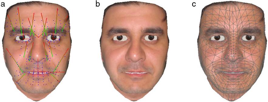
Fig. 3 The face animation system showing (a) muscle placements, (b) texture only, and (c) the underlying mesh.
Each test subject prepared themselves by applying markers to their face while looking in a mirror. To help guide the test subject a mannequin was prepared with an example set of markers placed on its face.
Markers were placed in facial locations that best represent face motion. The current marker test setup is displayed in Fig. 4.
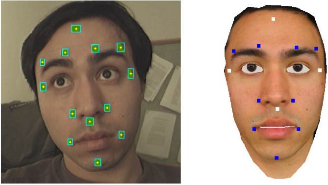
Fig. 4 Marker placement on the face, for the real and virtual cases. White points on the virtual model indicate anchor markers: the forehead, to the outer side of the left and right eyes, and below the nose.
Algorithm 1. Marker tracking algorithm
1: while Stereo image pairs from a video stream do
2: for Subregions of images if marker template initialised, else for entire image do
3: Color segmentation using a color predicate, median filter, and connected components analysis.
4: end for
5: Merging nearby components of similar color.
6: Computing centroids of connected components as potential marker locations.
7: if Marker template initialised then
8: Assign new marker positions; if marker temporarily lost retain previous position.
9: Triangulate marker positions based on marker template correspondences.
10: end if
11: Optionally:
12: if Suitable candidate markers found then
13: Initialise marker template based on their locations.
14: end if
15: end while
A marker template was constructed and tracked through the video stream, the procedure is given in Algorithm 1. The marker template defines the number of markers to be tracked within the image along with their position and velocity. The template provides robustness against any extra erroneous localizations from being considered. After definition, only the areas around current marker locations need to be processed and searched in, thus reducing computation time. Marker correspondence between stereo frames can be found with respect to the scan order and epipolar geometry condition of the stereo cameras. These correspondences can then be triangulated to recover the 3-D locations.
A subset of the template markers were designated as anchor points (shown as white points in Fig. 4). These anchors are located where a good estimate of the head rigid motion can be taken. They should not be affected by facial expressions as they are used to define a local head coordinate frame. The construction of a local coordinate frame is described in Section 5.1.
A marker is considered to have disappeared if a new position that is below a certain distance threshold cannot be found - in this case the previous marker position is carried through into the current frame. In practice this works adequately for the temporary loss of markers, e.g. in the case of an object such as the hand briefly occluding the face when the face is not moving substantially.
The presence of noise within the system causes jitter in the triangulated 3D marker positions. Noise sources include optical distortions, imaging noise and inaccuracies in the calibration. Past experiments showed that a small amount of positional averaging halved positional variance (Woodward & Delmas, 2005a). Therefore, an empirically determined, temporal mean filtering over three frames was applied to stabilize 3-D marker positions. This gave a noticeable improvement in marker stability, reducing the standard deviation in marker position estimation from 4.5 mm to 1.6 mm at 1.2 m.
Each stereo frame was time-stamped and the relevant data is saved along with the frame’s triangulated marker points as the system runs in real-time. Alternatively, the system allows for stereo image sequences to be saved and processed off-line.
5.1. Head local coordinate frame and reference marker positions
In order to estimate the non-rigid motion of facial expressions rigid head motion must be accounted for. This was achieved by constructing a local coordinate system based on the four anchor markers, shown in Fig. 4. The center point of the four markers acts as the center of gravity, or translational component. The four marker points a 1, a 2, a 3, a 4 are arranged so that the vector from a 1 to a 2 is orthogonal to the vector formed from a 3 to a 4. These can be used to create the local coordinate frame R = (r 1 r 2 r 3) as follows:
The calculation ensures that the coordinate frame is orthogonal. Rigid motion was removed from each frame by subtracting the center of gravity from the triangulated marker positions and multiplying the results by R T .
A small amount of movement was apparent for some of the anchor points, particularly the one placed above the lip. This was unavoidable for this approach but was dealt with by knowing that a minimum of three points can be used to create a co-ordinate frame for rigid motion. Also, for each test subject a neutral expression was recorded to provide default reference marker positions (a neutral state), for all markers, within the local head frame. This reference frame can be acquired during the first few seconds of marker motion capture. To do so the test subject is asked to keep their face still and without facial movement (head movement permissible). Reference marker positions allow for the calculation of divergence vectors from the neutral state, and are also used in the RBF mapping procedure in Section 6. These vectors are used to create the virtual performance.
6. Marker to model assignment and personalized 3-D face model creation
A RBF mapping was made between 3-D marker points and corresponding points on a face mesh based on the neutral reference marker frame and the neutral face mesh. The marker performance can then be translated into the virtual mesh local coordinate frame by giving the 3-D marker positions to the RBF mapper (as in Equation (6)). The resultant mapped positions can then be measured as divergence vectors of marker vertices from the mesh neutral state.
6.1. Radial basis functions for mapping
Radial Basis Function (RBF) interpolants possess desirable smooth properties (Farfield Technology Ltd, 2011) and have successfully mapped generic face models to subject specific face data (Woodward & Delmas, 2004, 2005b). They are particularly desirable as a scattered data interpolant and have been applied in areas such as approximating noisy data, surface smoothing and reconstruction (Carr et al., 2001; Farfield Technology Ltd, 2011), image morphing, and even for facial animation (Noh, Fidaleo, & Neumann, 2000).
The presented face mapping approach takes a user specified subset of the generic face model’s vertices and assigns values at these locations that represent displacements for a single spatial coordinate between the generic model and target face model. These correspondences are assigned between fiducial points on each face surface. Thus, the mapping of all points need not be specified manually; the set will be much less than the number of points contained in the source dataset.
This can be thought of as specifying a set of N samples from a 3-D function, f(x), at coordinates, X = (x 1, .. ., x N), x i = (x i , y i , z ), xi (ℜ3, whose values, f = (f , .. ., f N ), represent displacements between the two face models along a particular axis. A RBF, s(x), is then fitted to this data to approximate f(x). This is performed three times, once for each spatial axis, to calculate 3-D displacements.
A RBF has the general form:
where p(x) = c 1 + c 2 x + c 3 y + c 4 z is a linear polynomial term defining a plane in 3-space, a i is a real number weight, |x - xi| specifies the Euclidean distance between x and x i and φ is a basis function. The biharmonic spline, φ(r) = r, is used as the basis function as functions of three variables are being fitted, where r is the Euclidean distance. The biharmonic spline is a smoothing interpolator appropriate for 3-D objects such as human face models (Carr et al., 2001).
For the mapping of a 3-D point, x, from the generic model to an equivalent point, v, that fits the proportions of the reconstructed data, Equation (5) becomes:
The coefficients of the polynomial vector term p and the real valued vector weights a i can be determined using linear least squares. The RBF approach finds a mapping that will depend on the quality of correspondences identified between data sets. Creation of the personalized face model is completed by entering the points of the generic face model into Equation (6). The output positions are the interpolated values best approximating the original reconstructed face dataset.
6.2. Creating a personalized model
Results from the associated work on 3D face reconstruction by An, Woodward, Delmas, and Chen (2005), Woodward, Delmas, and Gimel’farb (2008), Woodward et al. (2006) can be combined with the generic face model and animation system described here to create a personalized 3-D model able to create novel expressions. Radial basis functions (RBF) were used for a non-rigid mapping between a personal 3-D face and the generic face. RBFs require only a small number of correspondences between data sets that describe the different proportions between the two faces. The vertex distribution and resolution of the generic face model must be preserved, so this interpolation strategy was appropriate. The personalized faces found in Section 9 were created in this manner.
7. Muscle inverse kinematics to drive face animation
Triangulated 3-D marker positions can now be mapped and applied to the face model. Changes in their positions drive the face muscles through inverse kinematics. This section describes the process of creating a complete virtual performance given a set of 3D markers, their motion over time, and a face animation system.
Marker divergences were measured from the neutral frame, mapped into a virtual face model’s local space. Each marker was matched with a vertex of the mesh. Upon initialization the muscles that influence each marker must be found. This is simple as each muscle has an area of influence. When a marker moves, virtual muscles must be updated to deform the mesh to place the corresponding vertex on the mesh as close as possible to the marker. Inverse kinematics was used to achieve this.
Inverse kinematics is the calculation of parameters for a kinematic chain to meet a desired goal position g, when starting from an initial position e. Applied here, the desired end position would be a 3-D marker position tracked by the vision system. The initial or current position is considered to be the location of the vertex on the mesh corresponding to the marker.
In the literature the vertex e is known as the end effector of a kinematic chain. The kinematic chain consists of a set of joints: namely the subset of muscles or jaw affecting a certain marker. Since only the contraction values of each muscle or the rotation of the jaw are dealt with, each joint possesses one degree of freedom (DOF). A degree of freedom (DOF) refers to an anima table parameter for each vertex-marker pair within the virtual face, where the animatable parameters are the muscle contraction values and jaw rotation. Each vertex-marker pair will have an associated set of muscles which affect it, their number is the vertex’s DOF. Likewise, each end effector, or marker position has 3-DOF, describing its position in 3-space. Collectively all of these parameters describe the system state and their change provides the virtual character performance. The locations of markers suffice to plan for the animation and 3-D motion capture data provides a simpler way to generate a performance based when opposed to forward kinematics, where each muscle contraction value must be determined.
7.1. Solution formulation
Let Φ = (ϕ 1 , ϕ 2 ,…,ϕ N ) ( ℜ N represent the vector of joint parameters (the muscle DOFs) and e = (e 1, e 2, e 3) represent a vector describing the end effector DOFs, in this case a vertex position. Let f be the forward kinematics map of a kinematic chain. This function computes end effector DOFs from muscle DOFs:
Considering a single face vertex, e, and its marker correspondence (target position) g = (g 1, g 2, g 3), the inverse kinematics problem is to compute the vector of muscle DOFs, Φ, so the vertex of a face coincides with the marker position; e = g and the desired positional change of e is d = g − e:
Unlike forward kinematics, solving f -1 is non-trivial as f is non-linear and there may be multiple or no possible solutions. An iterative numerical solution can be found with the Jacobian matrix J of f, i.e. the function can be followed to a minima through the knowledge contained in J:
where M = 3 to specify a vertex position in ℜ3 and N is the number of muscles affecting a vertex (which is automatically calculated during initialization). For an incremental step in pose, the change in end effector position, caused by a variation in joint DOF state, can be estimated by first order approximation:
Hence, for inverse kinematics an update value (( is calculated based on:
where if possible Δe≈d. In general, Eq. (11) cannot be solved uniquely and various strategies can be employed for choosing ΔΦ. Since f is non-linear, the Jacobian approximation is valid only near the current configuration of e, Φ, therefore, the approach taken is to iteratively update joint DOFs by values of ΔΦ until Equation (8) is satisfied.
A fast and simple iterative gradient descent solution was chosen that uses the Jacobian transpose of marker position with respect to muscle contraction (or jaw rotation around its axis) (Baxter, 2000). This method is computationally inexpensive since there is no inversion of the Jacobian matrix to perform. It also localizes computations since the DOFs can be updated before the entire Jacobian is computed.
7.2. The Jacobian Transpose method
The transpose of J is used instead of the inverse:
where the step e is given as:
in the direction of the goal marker position g. The scale factor β is used to limit the step size since non-smooth functions are involved. The value of β could be tuned for each marker since smaller step sizes must be taken when the number of influencing muscles increases and in turn the complexity of marker movement. The side effect of this is an increase in the number of iterations required for a solution. The Jacobian Transpose method is justified in terms of the principal of virtual work, which provides a relationship between an end effector movement and an internal joint - by analogy the distance to the goal g is considered to be a force pulling e, and joint torques are equated to changes in joint DOFs, ΔΦ (Baxter, 2000; Buss & Kim, 2004). This analogy is inexact and non-linearity prevents the end effector reaching the goal in exactly one step, which is why the process must be iterated. If β is small enough then the method always moves closer to the goal g: by taking d= g - e and Equation (10) d ≈ JJ T Δe = βJJ T d, it holds that JJ T d(d ( 0, i.e. the movement of e will always be in a direction less than 90 degrees with d (Buss, 2004).
The Jacobian matrix can be built by looping through the joints in the kinematic chains and evaluating their DOFs. It relates the change in end effector position with the change in kinematic muscle contraction values. Entries of J specify DOFs and depend on the type of joint - muscular contraction is a linear joint and jaw rotation is an angular joint.
For a muscle DOF a vertex e is draw toward the muscle’s origin o. The possible values for the DOF are bounded as muscles have a physical contraction range. A change in the DOF φ gives a movement along this direction:
A 1-DOF rotational joint models jaw motion, its entry in the Jacobian measures how the end effector, e, changes during a rotation about its axis:
The rate of change in the position of e is in a tangential direction to the rotation axis a, scaled by the distance of the axis to e, r'. Equations (14) and (15) form columns of J.
7.3. Pseudo-code for muscle inverse kinematics
Pseudo-code is given in Algorithm 2; markerCount gives the number of markers being tracked and affected Muscle Count(j) specifies the number of muscles affecting a particular marker j.
Algorithm 2. Muscle inverse kinematics
1: for all i such that 0 ≤ i ≤ iterations do
2: for all j such that 0 ≤ j ≤ markerCount do
3: for all k such that 0 ≤ k ≤ affectedMuscleCount(j) do
4: Estimate Jacobian transpose entry,
Equations (14) or (15) depending on muscle type. Matrix is implicit as entries can be processed in order.
5: Pick approximate step to take - as in Equation (13).
6: Compute change in muscle (joint) DOF - as in
Equation (12).
7: Apply change to DOF -ϕk = ϕk + Δϕk.
8: Contract virtual muscle with the new parameter
value φ k to obtain new position for e j .
9: end for
10: end for
11: end for
The resulting animation can be saved to file or processed in real-time depending on the processing power of the hardware platform.
8. Benchmarking against state of the art techniques
8.1. Marker vs markerless fiducial points tracking
We performed additional experiments to compare the accuracy of marker-based tracking with the state of the art techniques in 2-D and 3-D face feature points extraction, namely, Active Appearance Models (Edwards, Taylor, & Cootes, 1998), 2-D Constrained Local Models (Wang, Lucey, & Cohn, 2008) and 3-D CLM (aka CLM-Z) (Baltrusaitis, Robinson, & Morency, 2012). We first created a new database for the comparison experiment which includes 7 subjects, each recording two similar synchronized stereo video sequences - one with markers and another without. Each video shows the subject going through the six universal expressions of happiness, sadness, surprise, fear, disgust and anger plus a neutral face (see Fig. 5). The length of each sequence ranged from 336 frames (11.2 s) to 528 frames (17.6 s), averaging 442 frames (14.7 s) for a combined 3000 images. The sequences were recorded in a quickly setup and relatively controlled environment with good lighting, a featureless background, a good quality 3-D camera (FujiFilm 3-D W3) and all the subjects were placed in the same location. Following the framework developed in Woodward et al. (2012) and our latest results in stereo matching published in Gimel’farb, Gong, Nicolescu, and Delmas (2012), the stereo camera was calibrated to remove lens distortion and rectify the images. Stereo matching (here 1-D Belief Propagation) was then applied to produce depth maps. The latters were both both used for CLM-Z and to obtain 3-D coordinates of any point on the face and the 3-D coordinates of our 13 markers model.
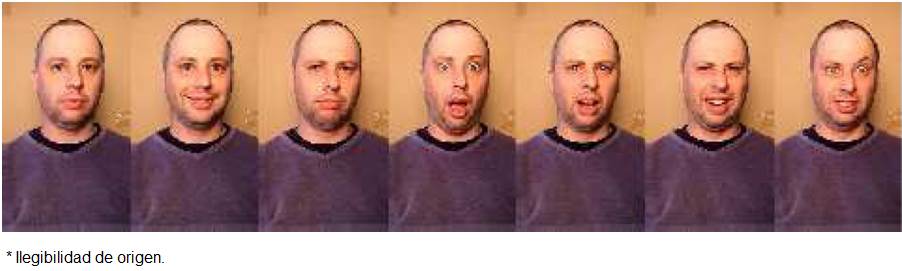
Fig. 5 Images extracted from our comparison database: test subject: Trevor. From left to right, showing the 7 universal expressions of neutral, happiness, sadness, surprise, fear, disgust and anger.
8.1.1. Active Appearance Model
For each technique we obtained code form the web and did no retrain on our images (since our system if training-free). We selected the code offered by T. Cootes http://personalpages.manchester.ac.uk/staff/timothy.f.cootes/software/am_tools_doc/index.html as the AAM tool-kit comes with training tool that allows manually drawing of contours on a series of facial images; and then adaption of the contour set as the sequence evolves. This allowed an effective training of this implementation on a set of the authors’ face images. The resulting model was able to match neutral faces quite well (since neutral was the first expression in the sequence), but failed each time a new expression was made (e.g. see Fig. 6). The general impression was that a lot of tedious training would be required to generate a good model each time new a new face is to be processed.
8.1.2. 2-D CLM
We evaluated the 2-D CLM version implemented by Yan, Xiaoguang, available at https://sites.google.com/site/xgyanhome/home/projects/clm-implementation, which followed: Wang et al. (2008) and Cristinacce and Cootes (2008). We used the model provided with the source code, thus no training was needed. If not initalized close to the actual face it was found that that the initial template did not fit well the first image face features. However after a couple of frames, the template evolved and appeared to find the correct orientation of the face. This implementation was slow to adapt to changes in facial expressions and did not track mouth movement very well. While very little additions were made to the source code to run properly, manual hardcoding of the initial template location roughly in the vicinity of the face features of the first image (achieved by changing constants hardcoded in the source code) was necessary. Our initial tests found 2-D CLM prone to errors due to the existence of facial hair, lighting and skin tone variations as well as an open mouth throughout images (e.g. see Fig. 7).
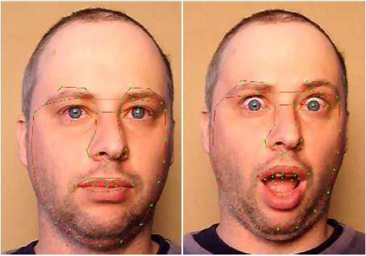
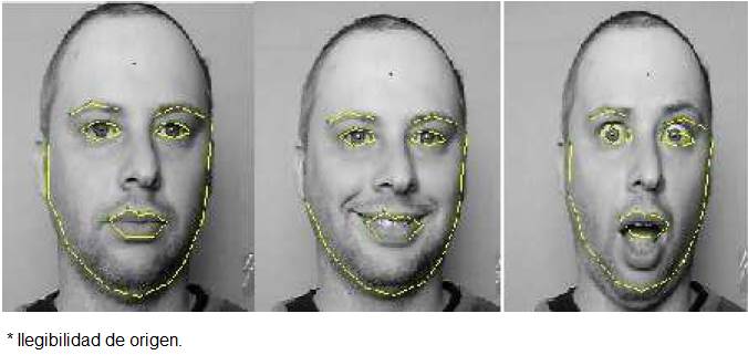
Fig. 7 2-D CLM face feature detection: test subject: Trevor. From left to right, showing 2-D CLM tracking results for a neutral and surprise facial expressions.
Both AAM and 2-D CLM failed to correctly track face features on a limited sample of images of our database and were excluded from the comparison with our marker-based approach leaving CLM-Z as the last state-of-the-art technique to compare to.
8.1.3. CLM-Z
Our CLM-Z implementation was kindly provided by 2. While this library did come with several different implementations, we had to write our own front-end program to get the source code to run through all the images of our database and render the relevant points to a data file. The CLM-Z implementation came with a pre-trained classifier and thus no training was required.
Upon start up, the algorithm grabs the first image in the sequence to initialize its template. This may take a relatively long time, averaging up to 2 min for a mid-range PC. Once initialized, the subsequent updates and feature extraction through successive frames was quite fast, achieving close to real-time performance.
We used an implementation of CLM-Z with a generic face template for the marker-less sequences. CLM-Z tracked points roughly in the region of the appropriate facial features. CLM-Z coped well with head tilting in the neutral expression state. There were no jumps in feature point tracking on static sequences as most points remained in the neutral state. However, we found that CLM-Z frequently failed to be in perfect synchronization with the images, often producing lagging or misaligned features (see Fig. 8). On sequences with full facial expressions evolving, the detected eye shape seemed to be much smaller than the actual eye. As well, the mouth was often inaccurate with facial hair confused as a mouth in some cases. Tracking stopped following the mouth for wide smiles or if the mouth was wide open, e.g. surprise actions (see Fig. 9). Across the 7 sequences, CLM-Z failed to accurately find eye shape and location in 33% of the images (from 5% to 100% errors across each of the 7 sequences for mouth shape extraction and between 0% and 100% error across each of the 7 sequences for eye shape extraction), 67% for mouth shape and location, respectively. None of the sequences recorded perfect extraction of face features, necessitating the use of manual extraction for some cases. CLMZ failed when facial hair was encountered; eye detection was weak in most cases and mouth corner detection failed with wide smiles or unexpected shapes, a feature common to most contour based and appearance based techniques when dealing with the mouth.
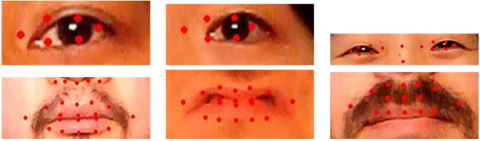
Fig. 8 Examples of tracking errors with CLM-Z across four different sequences. Often the eyes are misaligned, facial hair confuses the size and location of the mouth, and the fine shape of the mouth is also lost.

8.1.4. Marker-based tracking
For our marker-based system, we used our sequences with markers. The markers were first segmented using color segmentation in HSV color space, then a basic blob tracking algorithm was used to track the blobs across subsequent frames. On all test sequences, the marker’s blue color was clearly distinct from facial features allowing it to be tracked across frames easily and with high accuracy. Markers were only lost when the subject’s head was rotated such that the marker was hidden from the camera, or when the subject’s head moves out of the field of view of the camera. In contrast to the best-performing CLM-Z, only 3.8% of the 3000 images of our database failed to have all 13 markers tracked across both cameras, with all but two sequences having 100% perfect extraction. Overall, of all the markerless approaches tried, CLM-Z had a slow start-up time but performed the best, since it was easy to see the dominating expression. AAM performed the worst due to poor training. The points extracted in all three models were far from perfect with the most accurate fiducial points extraction achieved by our marker-based approach. Facial hair, lighting and skin tone as well as pronounced open mouth expressions heavily affected face feature tracking for markerless techniques. Of note is that our markers were created from scratch using blue paper and skin-friendly glue at a close to zero cost, in contrast with more professional marker requirements. Most failed images originated from blue color saturation around some markers again considering a fast setup using off-the-shelf tripod, lighting, camera settings, background and subjects positioning. Following the framework developed in Woodward et al. (2012) and our latest results in stereo matching published in Gimel’farb et al. (2012), the stereo cameras were calibrated to remove lens distortion and rectify the images. The cameras were automatically synchronized over the firewire bus. This ensured stable tracking of markers and no clock drift occurred. Stereo matching (1-D Belief Propagation) was then applied to produce depth maps. As mentioned early, this was used for CLM-Z, to obtain the 3-D coordinates of any point on the face and the 3D coordinates of our 13 markers model.
9. Experimental results and system analysis
A selection of results are shown in Fig. 10; three test subjects performed the six universally recognizable facial expressions (Ekman & Friesen, 1971) in front of the system, a personalized 3-D model was created from their faces and tracking data drove the facial animation system.
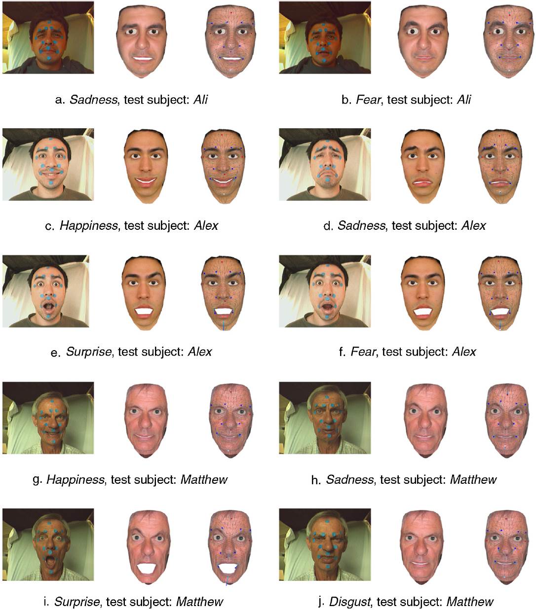
Fig. 10 Expression creation for a range of subjects and. For each subfigure, from left to right, showing the original left image from the stereo pair, the virtual result, and the associated mesh and motion vectors of the marker points from a neutral state.
Experiments show that the proposed system is capable of reproducing facial expressions from marker motion. From running the system it was found that different test subjects articulated the same expression using different muscles. Also, it was difficult for a test subject to perform an expression when no emotional tie was involved. Thinking about what muscles to move and generating an expression sometimes required self experimentation and looking at one-self in the mirror. Therefore it is easy to understand why there is a need for directors in movie performance capture situations.
Details in important areas of the face that are not currently modeled include the eyelids, lips, teeth and inner mouth. This impacts on the visual accuracy of the virtual expressions and future work would look to improve the face model in these areas. This loss of detail can be seen in Fig. 9, Matthew, where important cues for the expressions are conveyed through the eyes. The surprise expression for test subject Matthew (Fig. 10(i)), clearly shows the loss of information in the mouth region and how important this region can be for conveying expressions.
For Matthew’s disgust expression, in Fig. 10(j), shadowing cues are lost around the flanges of the nose in the virtual expression, despite the motion vectors being correctly captured.
During a performance, some people had better control over certain muscles of their face than others. An example of this was the control of the inner and outer frontalis muscles of the forehead that influence the eyebrows, or the individual control of the labii nasi on the flanges of the nose. For test subject Ali there was little movement in the motion vectors for his expressions, reflecting in their poorer representations in the system when compared to other test subjects. Conversely, test subject Alex’s expression images and motion vectors showed large scale movement, reflecting the visual correctness in expression reproduction shown in Fig. 10(c)- (f).
Fine tuning of the preset muscle locations and parameters when mapping a new face model was sometimes needed to improve results or to correct muscles with too great an activity on the mesh. An example of this is the asymmetry in face movement for test subject Ali’s eyebrows where the right eye would often appear slightly larger after an expression was simulated (as seen in Fig. 10(a)). Incorrect asymmetry in the eyebrows and in the sadness expression was also noticeable for Alex (Fig. 10(d)). This asymmetry can be understood by considering the mapping procedure. In reality each person’s muscles have slightly different locations and strengths, thus move in slightly different ways - a small amount of positional and morphological difference is to be expected between the same muscles in different people. One way to improve this would be to set plausible limits of muscle contraction ranges and let the system go through a training phase where it would rescale its activity based on a subject performing a range of expressions.
One of the main issues with the expression system is that there are potentially multiple solutions for a vertex position when it is under the influence of more than two muscles, an effect that is amplified with noisy data. In this situation, equal contributions of muscle contraction could be assumed, but this may not be the case in reality if some muscles are stronger than others. This ambiguity does not exist when handcrafted expressions are created for animation. Two opportunities for improving upon this issue are the creation of a more advanced animation system that may incorporate prior learning, e.g. the use of a restricted set of basis expressions, and investigating the effect of adding more markers.
A marker based system can only pick up the sparse movement of the face since tracked points are not dense enough to account for fine movement. This was difficult as some people naturally had minimal face motion for some expressions.
Camera noise was more apparent in dark regions and around edges. Color predicate detection used the YUV color space, so low intensity regions were more ambiguous and were thre sholded out of consideration. Noise in the detection of 2-D marker positions affected the quality of 3-D triangulation, giving fluctuations in the location of marker centroids. This was dealt with through temporal smoothing as described in Section 5. The majority of face motion can be described in 2-D and the error from the two cameras influences the determination of marker location, however a 2-D system would find it much harder to account for rigid 3-D head motion and any slight shifting of perspective in the face as the head moves.
The RBF approach provided an effective means of mapping markers to a face model. There is no restriction on the choice of face model and it does not have to represent the test subject. RBF is inexpensive and the mapping coefficients for a particular setup need only be estimated once based on a neutral face expression. However, asymmetries in the 3D mapping process may affect expressions. This is due to positional differences in the placement of markers on a test subject’s face with respect to the selected vertices of the generic model.
10. Expression estimation
Facial expressions can be handcrafted using the face animation system and setting muscle contraction parameters. An experiment was performed to test if the marker tracking system could be used to estimate a given expression from a prebuilt set of expressions. The set of six universal expressions were modeled with the animation system and saved. The test subject then aimed to generate these expressions as best as possible. Fig. 11 displays the six universal expressions that were created with the animation system.
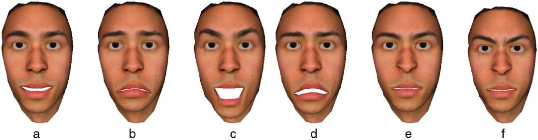
Fig. 11 The six universal expressions prebuilt into the system: (a) happiness, (b) sadness, (c) surprise, (d) fear, (e) disgust, (f) anger.
A simple method of expression estimation from marker motion capture can be performed by taking the Euclidean distance between the current muscle contraction vector a, derived from the current marker configuration, and a collection of prebuilt expressions b i, i ∈ [1, 6], described in the same form. It should be noted that because each individual expresses themselves differently, future work should create an extensive database of prebuilt expressions that can better represent variations within each class.
Fig. 12 displays curves of euclidean distance over time from each preset expression for a set of captured sequences in which the test subject, Alex, performed the happiness, sadness, surprise, fear, disgust, and anger expressions. The lesser the distance the closer a captured marker sequence is to a preset expression.
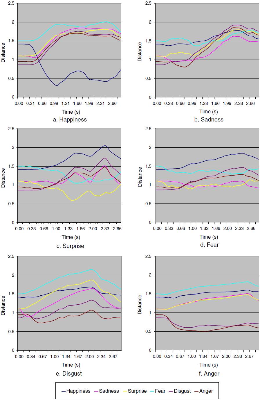
Fig. 12 Euclidean distances of muscle contraction vector from preset expressions; test subject Alex.
The test sequences began with the subject in a neutral face state and then moved toward an expression at maximal magnitude. It should be noted that the tail of the curves in the sequences represent the relaxation of the face away from the expression and back toward the neutral state. For all sequences this can be seen as the end of an expressive climax in the curves, at 2.4 s, 2.2 s, 2.4 s, 2.3 s, 2.1 s, 2.7 s for Fig. 12(a), (b), (c), (d), (e), (f) respectively.
Two criteria can be considered when analyzing the plots: by considering an empirical threshold distance from a prebuilt expression and secondly, the relative ordering of distances from each prebuilt expression. As would be expected, the ordering of distances is consistent at the beginning of the figures when the face is in a neutral expression, then curves diverge as the subject performs.
As shown in Fig. 12(a) the happiness expression is correctly characterized. The happiness curve dips sharply for the duration of the expression whereas the other curves collectively remain separated. This leads to an important point: the ability of the system to convey an expression is proportional to the complexity with respect to the number of muscles involved in the expression. For example, the happiness expression, conveyed with a smile, mainly involves the left and right zygomatic major muscles. The animation system used only these two muscles; therefore there is less ambiguity of muscle activation when performing inverse kinematics on a happiness sequence. In Fig. 12(a) the happiness curve is strongly discerned and its distance from the preset happiness expression is the lowest when compared to the distance curves of the other expression sequences.
When the subject performs a sadness expression, the curves shown in Fig. 12(b) move into a consistent trend. The correct sadness curve remains the closest in distance over the expressive section of the sequence, even though all curves follow a trend of increasing distance from the prebuilt sadness expression. If a system’s estimated expression criterion was based around choosing the closest expression then this would present a valid result. Visual results in Fig. 10(a) (d) (e) show that the system can correctly create this expression.
The surprise expression in Fig. 12(c) is correctly characterized giving a graph in a similar vein to the happiness expression. The fear expression is not recognized, shown in Fig. 12(d), pointing to the difficulty the system had in conveying this expression. It is inferred that the complex motion for fear around the upper facial region cannot be characterized well with the only 13 markers and 21 virtual muscles. Two characteristics that describe fear are not modeled with the current animation system. Firstly the slight raising of the upper lip and secondly, the eyes opening wide. Both of these aspects would probably require image processing to capture the outlines of the fine lip movement and the widening of the eyes, something for consideration in future work.
The disgust expression is incorrectly characterized, but from Fig. 12(e) its distance curve remains second only to anger. The reason for this was the similarity in visual representation of the prebuilt disgust and anger expressions. Notably the lowering of the eyebrow regions through contraction of left and right lateral corrugators, the raising of the labii nasi and lip movement (something the current animation system is incapable of). This can be appreciated when one considers the variability between individuals in how they express disgust. In fact this expression would best be represented by a set of disgust examples.
Lastly, the anger expression is correctly characterized, as shown in Fig. 12(f). Here the similarity between the anger and disgust expressions is shown in the trends of their distance curves. They are readily separated from the other four expressions due to the contraction of the lateral corrugators to lower the eyebrows, something not occurring in the other expressions.
Judging these expression sequences has given insight into the effectiveness of the animation and the expressiveness of a sparse set of markers, along with the visual cues that are important or those that were possibly lost. In summary, a sparse set of markers can be used only as a guide to motion performance - as is often the case in most marker based systems - since fine nuances of an expression are not captured. Also, to extend this system to robustly recognize facial expressions, an extensive database of prebuilt expression examples should be created. It has also demonstrated the difficulty in differentiating between some expressions, such as disgust and anger.
11. Conclusion and future work
A complete system for marker based motion capture and face animation was implemented. Test subjects place markers on their faces to drive the expressions of a 3-D face. The benefits of using a marker based system are its robustness in motion tracking and relatively low computational costs in relation to markerless motion capture approaches. RBF mapping decouples the test subject’s face proportions from the face model, avoiding the need for time consuming model creation. It also means that marker motion can be retargeted to a wide range of human or non-human faces through estimated muscle activation parameters.
With regards to future work, it was found that the quality of animation greatly depends on the animation system and how well it can mimic marker motion. However, our current face model does not possess important components such as the teeth and tongue, a full back of the head with ears, hair, and eyelids all important aspects for conveying expression. Also, the static face texture does not convey subtle changes in skin reflectance and shadowing. To remedy this 3-D video data generated from the approach published in Woodward et al. (2008) was used to explore an alternative method for expression modeling in Woodward et al. (2012). A physically based skin system would provide better animation when a limited number of markers is used as it treats the mesh as a skin continuum, making it of benefit for creating novel animations. However, this does not guarantee that the final animation is representative of the actual expressions performed by a human test subject and computational requirements are higher.
A database of expressions could be created to estimate the validity of synthesized expressions and their recognition. An investigation on the impact of the number of markers on the quality of animation will be undertaken. This will determine a relationship between the expressive ability of the face animation system and its computational complexity.
Virtual muscles are easier to set up than approaches such as key-framing and skinning and are anatomically based. However, placing markers on a face can be cumbersome, especially if placement needs to be precise and repeatable. Still a marker based system is appropriate for creating a solution that has a low computational cost.
The affects of a large number of muscles and an improved face model, with a complete head and ears, will be tested. Finally, markers could also be used to drive alternate animation systems, e.g. key-frame based, since they are transferable between models and animation systems and a hybrid muscle and key-frame could be investigated.

