


 nueva página del texto (beta)
 Inglés (pdf)
 Artículo en XML
 Referencias del artículo
 Enviar artículo por email
 Citado por SciELO
  Similares en
SciELO
Similares en
SciELO 
 Permalink
1. Introduction
Over the past few decades, robotics has played a very important part in process automation, with robot manipulators assuming a leading role in the development of several productive areas. Nowadays, industrial robots are used for the automation of a variety of tasks such as assembling, transfer of materials, all kinds of welding, precision cutting of materials, palletizing, painting, remote surgical procedures, among many possible applications (López, Castelán, Castro, Peña, & Osorio, 2013; Siqueira, Terra, & Bergerman, 2011).
In general, industrial robots are employed to carry out repetitive jobs and/or those that require precision and speeds difficult to achieve by human beings. This has made it possible to improve the quality of products and the efficiency of their manufacturing (Ben-Gharbia, Maciejewski, & Roberts, 2014; Urrea & Kern, 2014). Therefore, industrial robots are increasingly used in modern and automated production processes, as well as in hazardous applications, in which their use is clearly justified.
On the other hand, industrial robots can perform tasks during many hours per day without getting tired or losing precision or effectiveness, because they are currently highly developed and robust devices that practically do not fail. Thus, to know, study, improve, reprogram, and adequate these systems to different scenarios becomes necessary, so users can profit as much as possible from them (Gómez et al., 2014; Siciliano & Khatib, 2008; Urrea & Kern, 2014).
The present work arises from the compelling need of having real platforms to carry out scientific research and its corresponding validations. The implementation of a robot manipulator with 6 DOF allows for improving the control systems of industrial robots, in addition to proposing and validating new control systems. Therefore, this paper presents the process of design and construction of a robot with a SCARA1 configuration, which has great application in the present day industry (Urrea & Kern, 2012).
2. State of the art
2.1. Industrial robots
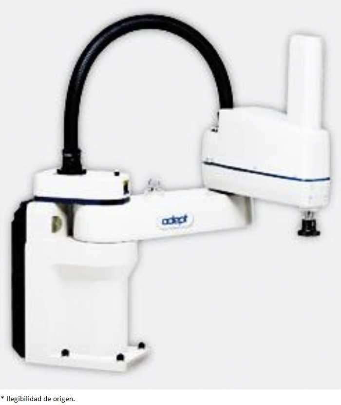
There are various types of robots, which depending on their physical configuration can be classified into many-jointed, mobile, zoomorphic, android, and hybrid. In the many-jointed category we have industrial robots like the one shown in Figure 1 (Adept - SCARA robots, n.d.).
An industrial robot can be considered as a set of integrated subsystems that correspond to a manipulator or mechanical arm, a terminal effector, motor elements or actuators, information sensors, and controllers.
SCARA manipulators possess the features necessary for performing a stable work with precision and speed (Yamazaki, 2014). Due to this reason, they are widely used in industrial assembly tasks (Wang, Liu, Wei, Xu, & Zhang, 2014). Different applications have been developed for these robots, for instance, Wang et al. (2014) design a control system with double CPU, in which the analysis of inverse kinematics and dynamics are implemented based on a Robotics Object Oriented Package in C++ (ROBOOP). Furthermore, Surapong and Mitsantisuk (2016) use a SCARA robot to implement a disturbance observer (DOB) instead of a force sensor to control the position and estimate the external force. On the other hand, in Jo and Cheol (2001), a fuzzy sliding mode controller is designed to improve features in fast operations as well as the commutation effect of this type of controllers. This algorithm is implemented in a SCARA robot by means of a digital signal processor (DSP). Likewise, using a robot of similar features, Rossomando and Soria (2016) implement an adaptive neural network sliding mode controller to compensate the dynamic variations of the robot. Furthermore, Prajumkhaiy and Mitsantisuk (2016) present a method to compensate friction force in a SCARA manipulator to reduce the heat generated, thereby preventing robot damage during operations that imply prolonged periods of work. Finally, Bruzzone and Bozzini (2011) conduct a study aimed at improving energetic efficiency in this type of manipulator robot.
2.2. Robot control
Robot control has the purpose of sending control signals to the joints to make a robot follow a specified trajectory. A number of control algorithms with different characteristics and complexities have been developed. Some strategies for joint control in robot manipulators that operate under the closed loop scheme are now listed: Decoupled Joint Control, Computed Torque, Adaptive Control, Gain Scheduling or Gain Planning, Adaptive Computing Controller by Reference Model, Adaptive Computing Pair Controller, Force Control, Robust Control, Control with Learning, etc. Out of the listed control strategies, the one used in this paper corresponds to the Decoupled Control, because we are only aiming to validate the correct functioning of this newly designed and implemented robot. This control technique is quite simple to implement, since it does not take into account perturbations generated between the robot's joints, i.e., each joint is controlled in an independent way commonly by means of one PID controller per joint. The PID controller intrinsically attempts to correct perturbations that produce errors, which must be canceled out (Siqueira et al., 2011; Urrea & Kern, 2014). This controller generates a control signal that corresponds to the sum of three terms: term P is proportional to the error, term I is proportional to the integral of the error, and term D is proportional to the derivative of the error. The following equation describes this type of controller:
 (1)
(1)
with e=ys p−y, where u is the control signal, e is the control error, ys p is the set point, and y is the measured process variable (real). The controller's parameters are the proportional gain K, the integral time Ti , and the derivative time Td .
In Table 1, the parameter values of the controller used in the SCARA manipulator are shown.
3. General design
3.1. Complete system
A SCARA manipulator, communicated with a PC-Controller that uses the MatLab/Simulink software (Mathworks, n.d.), is designed and built (Southern Plantaids Pvt.Ltd, n.d.). Since the robot and the PC-Controller must interact with each other, an electronic interface capable of performing the task is also developed, thereby constituting a link between both parts. The system's general diagram in Figure 2 shows the components of the system.

3.2. Robot
The materials used to build this robot are steel for the fixed parts (base, etc.) and aluminum for the moving parts (prismatic joint, etc.). A SCARA physical configuration is employed in this robot. Originally, this robot had an RRP2 configuration plus a terminal effector, to which two joints and a clamp have been added, with a resultant RRPRRP configuration that was selected because of its representativeness in the current industry. Figure 3 shows the design and dimensions of the robot.
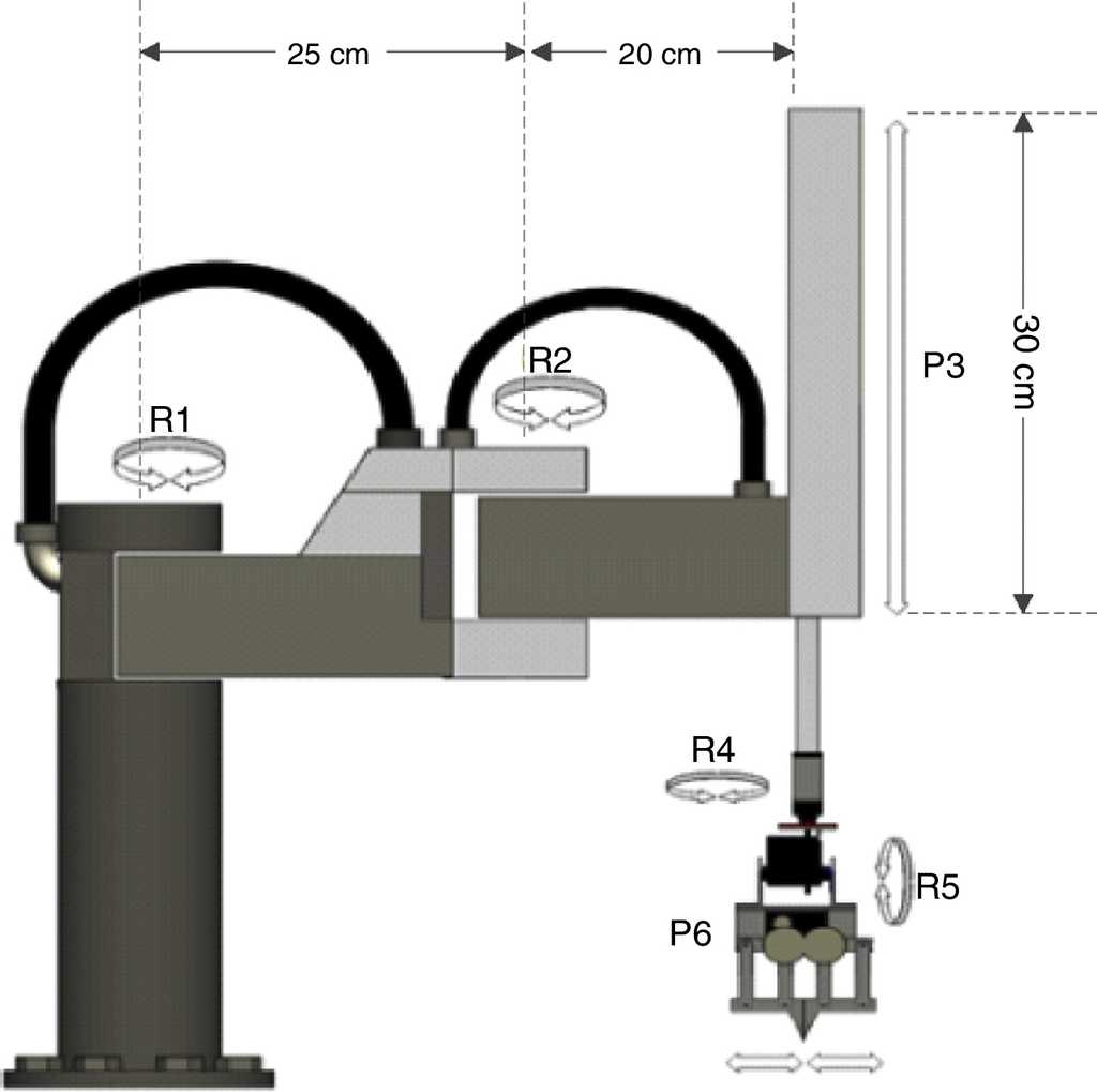
For the first three degrees of freedom (R1, R2 and P3), the ideal features of the motors are:
-DC motor with permanent magnets
-Gearbox with integrated planetary gears
-Gears ratio between 1/150 and 1/100
-12 VDC nominal voltage
-Absence of movement in the output axle of a stopped rotor
The selected motors correspond to DC motors with a gearbox containing axles rotated to 90°, 12 VDC and limited movement of the output axles when the rotor is stopped. These motors were chosen mainly due to their torque/size ratio, power supply method and availability in the national market. In Table 2, mechanical and electric features of these motors are shown.
Table 2 Motor features.
| Motor | VDC max | Ratio | Torque | RPM | I mxx. |
|---|---|---|---|---|---|
| R1 | 12 | 1/65 | 82 kgf cm | 50/47 | 7.5A |
| R2 | 12 | 1/65 | 45.9 kgf cm | 50/47 | 4.6A |
| P3 | 12 | - | - | 30 | - |
These motors are fed back in position by optical incremental two-channel encoders from disused printers. Such a sensor has a mini electronic card to sense the angular position by using a Darwin wheel rotational joints and through a straight belt for prismatic joints. Thereby, implementing various strategies for controlling the robot's joints becomes possible.
For the next two rotational degrees of freedom (R4 and R5), advantage is taken from the small weight and size of high torque HITEC digital servomotors. The last actuator of the robot (P6) is the one in charge of opening and closing the clamp. For this action a HITEC digital servomotor is also used, which obtains external clamping force feedback from a circuit that is connected to a force sensor. Table 3 presents the features of these servomotors. Figure 4 shows the four sensors used in the robot manipulator: two rotational encoder sensors (SR-1 and SR-2), a linear encoder sensor (SP-3), and a FlexiForce force sensor (SF-4).
Table 3 Servomotors features.
| Motor | Model | VDC | Torque | Operation range |
|---|---|---|---|---|
| R4 | HSR-5995TG | 4.8-7.4 | 30 kgf cm | 180° |
| R5 | HSR-5995TG | 4.8-7.4 | 30 kgf cm | 180° |
| R6 | HS-5645MG | 4.8-6 | 12.1 kgf cm | 135° |
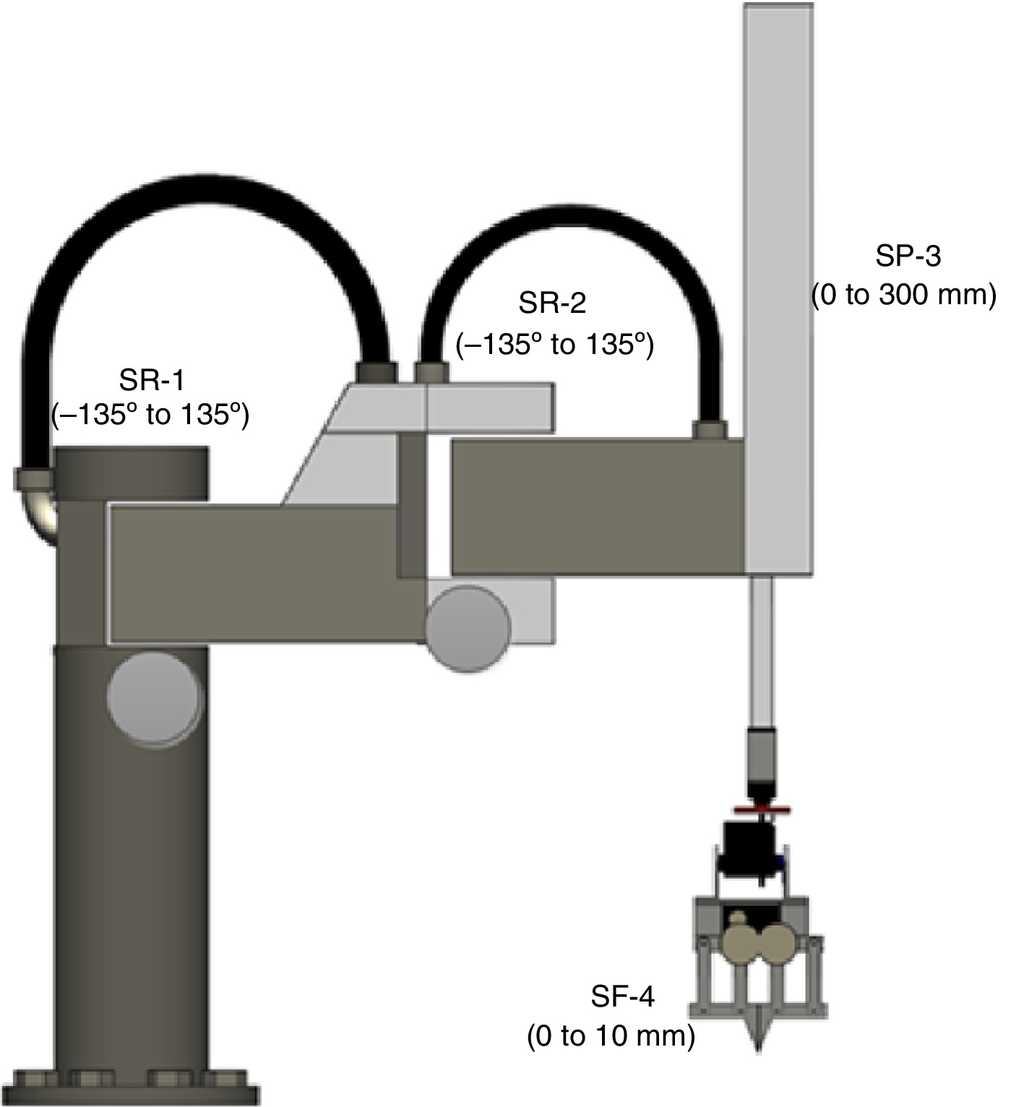
The operating ranges of sensors SR-1 and SR-2 are limited to an operating angle of 270° by the mechanical construction of base and R1 and R2 joints. In the case of the linear sensor SP-3, at design stage, a length of 300 mm was considered sufficient for this robot, taking into account its intended use. On the other hand, the FlexiForce force sensor, albeit analog, is programmed to be set at fixed values from 0 to 15, with these levels proportional to the clamping force exerted by the clamp on the object being held.
The work space of this robot is basically cylindrical, although in this particular case it resembles a cardioid quite closely (Fig. 5). The diameter of this cylinder/cardioid occupied by the robot is approximately one meter and its height is 30 cm.

3.3 Electronic design and interface
3.3.1 General description
The electronic interface is the link between the robot and the PC-Controller, as seen in Figure 6. It has the purpose of providing the drivers needed to convert the numerical data from the PC-Controller into signals for the actuators and to convert the signals coming from the sensors of the robot into numbers to be sent to the PC-Controller. The information is sent through a serial port using the RS-232 protocol.
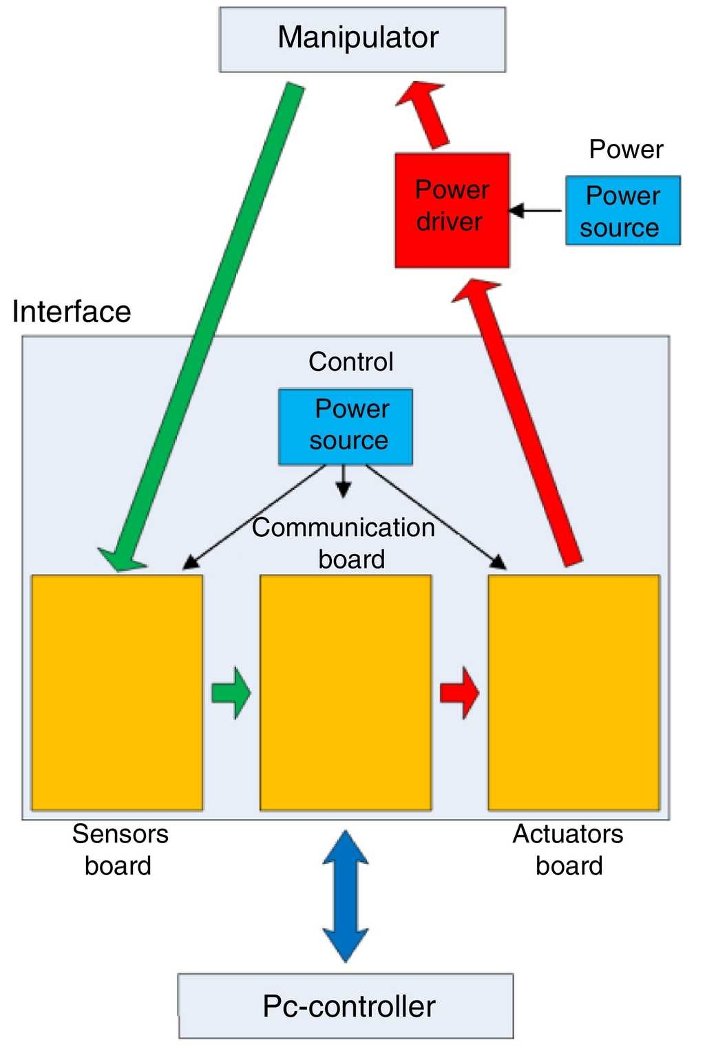
To simplify the design and implementation of this interface, three systems are considered: Communication Board, Sensors Board, and Actuators Board. These three boards are contained in a single box, as shown in Figure 7. In addition, they are interconnected and not fed electrically by the same power drivers of the DC motors and the servomotors of the robot. In this way, possible problems due to electric noise or interference that may cause poor operation of the electronic interface are avoided.

The technology used in the digital electronic devices of the interface is CMOS3, specifically the HC series, due to its advantages over other older technologies such as TTL in terms of speed, immunity to noise, energy consumption, etc. The microcontroller used to implement the interface's drivers is PIC16F628A, since it possesses multiple functions and reduced price. On the other hand, PIC18F25020 controller is used in the communication system, because of the number of input/outputs required.
To sum up, the system has four sensors and six actuators. In addition, drivers with electronics and microcontrollers that allow for the conditioning of communication signals are designed and implemented. Two microcontrollers are used to simplify the programming of communication in the interface: one exclusively for handling the data bus of the sensor card and sending data sentence to PC-Controller; the other exclusively for receiving data sentence from PC-Controller and handling the data bus of the actuators' card.
The drivers of the DC motors placed in R1, R2 and P3 joints are implemented on PIC16F628A microcontrollers programmed in assembly language by means of a PWM module integrated by hardware.
3.3.2. Initialization by interface
The interface allows for making an initialization of the robot without the need for it to be connected to the PC-Controller. To perform this initialization every time that the interface is turned on is compulsory. The initialization consists in positioning the robot in a predefined location, and then the drivers of the sensors adopt the angular and distance values corresponding to that position. This is necessary because the encoders are incremental, so they do not deliver an absolute position, but an incremental or decremental position with respect to an initial value.
The initialization routine is a sequential process that consists basically of the eight steps listed chronologically below:
4. Communication software
All the software elements involved and programmed in the PC-Controller are shown and detailed below. Their function is to communicate, generate the trajectories, and apply control over the actuators of the robot.
4.1. Generalities
The communication processes are classified into four algorithms: one that creates, configures and opens the serial port; one in charge of reading from the port and generating the input variables; a similar one that sets up and sends the output information; and finally one that allows closing the serial port.
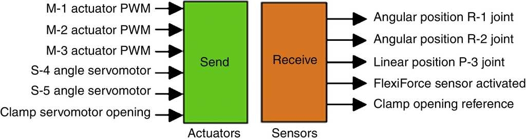
The control system is designed and implemented by means of MatLab/Simulink software. The application requires two blocks, one for transmitting the data and another to receive the data, as shown in Figure 8.
4.2. Control software
The robot has 6 actuators, from which we have:
1. In the three DC motors (M-1, M-2 and M-3), a closed loop control is applied.
2. In servomotors S-4 and S-5, a closed loop control is applied making use of the position control system (fast and precise) that is incorporated in these servomotors.
3. In the clamp, a type of On-Off control is incorporated, having as feedback the signal generated by the FlexiForce force sensor, which stops the closing of the clamp if the previously configured clamping force level is reached. This system is implemented in the drivers of both elements, and the PC-Controller has no influence on stopping that actuator.
From these considerations, control systems for actuators M-1, M-2 and M-3 are designed and implemented in the PC-Controller, and they are fed back in position by means of encoders SR-1, SR-2 and SP-3, respectively. Such systems are independent for each actuator, although all the blocks of the application are contained in a single Simulink model that is operated from the system's GUI4 application, where the trajectories are programmed and previsualized. This Simulink model includes the following blocks:
5. Trajectory generation
With the purpose of testing the functionality and versatility of the robot, a new graphic interface was designed, which enables the programming of the test trajectories that the robot must follow. That interface allows for programming ten steps per joint, and each step consists of an initial pause; a smooth movement by means of a cubic polynomial curve between two points; and a final pause. Figure 9 shows the system's graphic interface, which is composed of the following parts:
1. Trajectory programming boxes per joint that allow programming ten sequential steps, from top to bottom. They are programmed in the same way for joints R-1, R-2, P-3, R-4 and R-5.
2. Button that allows taking the robot to the default initial position.
3. Button that allows visualizing the curves of programmed trajectories, producing a graph.
4. Button that allows starting the execution of the Simulink model in charge of controlling the robot.
5. Button that allows stopping the execution of the Simulink model in charge of controlling the robot.
6. Clamp programming boxes into which only opening and closing times are entered. They allow enabling or disabling the use of the clamp as well as the input of the clamping force level of the clamp.

To generate the movement of a joint, position and time parameters must be entered according to a pre-established format, which allows the generation of a smooth movement of the joint, from the present position to the new objective point, allowing it to enter as part of it an initial pause and a final pause. The established format is the one shown below:

where Angle or Distance: New set point; Td: Initial pause time; Tm: Movement time; Tf: Final pause time.
The time parameters are incremental and not absolute, so they must fulfill conditions (2) and (3).
 (3)
(3)
 (4)
(4)
From (2) and (3) it can be concluded that Tm cannot be zero, which is the same as saying that initial Td cannot be equal to Tm. On the other hand, it is seen that the final time of step i is the starting point of step i + 1, and therefore the incremental logic must be maintained.
The curve generated by the application is cubic polynomial, which exhibits the advantage of providing a smooth movement at the joint. The movement starts at low speed and increases progressively; then, on approaching the objective point, the speed is reduced smoothly.
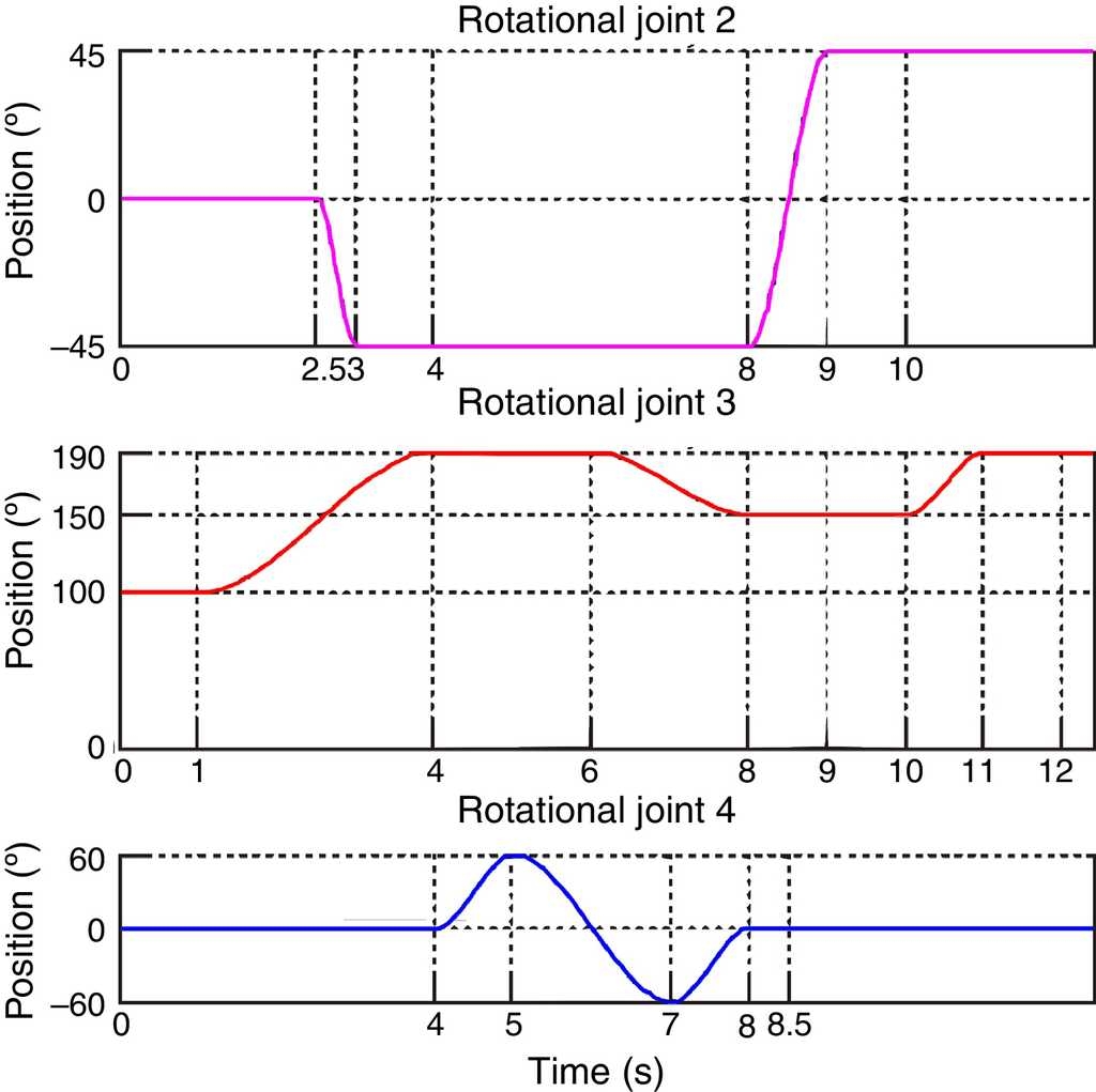
After programming the trajectories, the curves on which the entered times are indicated are generated, as shown in Figure 10.
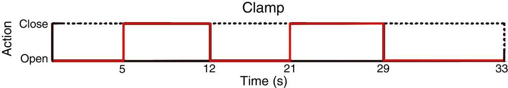
The programming of the clamp differs considerably from the programming of trajectories because its operating principle is not based on the position, but on the "open" or "close" states. The graph generated by the application for programming the operation of the clamp shows both states as a function of time, as seen in Figure 11.
The GUI application generates a general graph that includes the trajectories of the six actuators involved, which can have different execution times. Thus, the time at which the curves are generated and graphed is the same for all the actuators and corresponds to the longest programmed time.
6. Tests and results
The tests conducted with the robot consisted in the application of steps and trajectories to the joints at different speeds, R-1, R-2 and P-3 independently feedback control, and finally a test comprising a programmed task in which simultaneous functioning of all the joints is involved.
6.1. R-1 rotational joint
For R-1 joint, in both directions, Figure 12 shows in green the application of a 60° step and in blue the performance of the robot. This kind of signal is the one that generates the most abrupt response of the link, because at the beginning of the movement the position error is very large, so the controller makes the actuator move at high speeds that depend on the amplitude of that step.

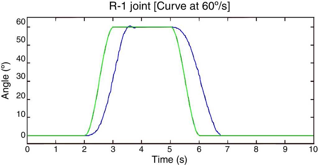
In general, the robot is not used to follow stepwise trajectories because they are very abrupt (especially at the beginning of the movement), but they serve to verify the efficacy of the designed and implemented controllers. Therefore, it is important to evaluate the performance of the robot by dealing with cubic polynomial trajectories, which allow the robot to start and finish the movements smoothly. Thanks to this, the follow-up of these types of trajectories is used very widely in real applications. Figure 13 presents, for R-1 joint, in both directions, the application of a cubic polynomial curve at a speed of 60°/s and the performance of the robot in green and blue, respectively. Similarly, Figure 14 presents the performance of the robot at a speed of 30°/s.

6.2. R-2 rotational joint
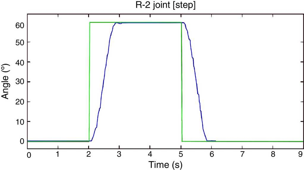
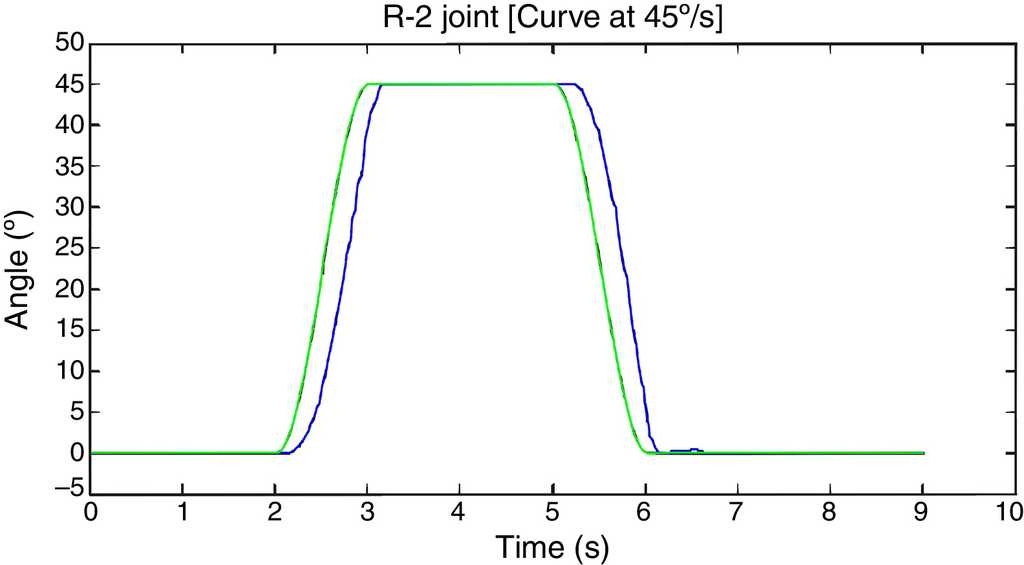
Now the same stepwise tests (Fig. 15) and the curves at speeds set at 75°/s (Fig. 16) and 45°/s (Fig. 17) are applied to R-2 joint.

6.3. P-3 prismatic joint
The tests performed on this joint are similar to the previous ones, with the difference that now three steps and three curves are programmed in each case. Figures 18-20 show in green the reference to be followed and in blue the performance of the P-3 prismatic joint.


6.4 General tests
Figure 21 shows the programmed trajectories (green) and the executed trajectories (blue) for a simple test task of the robot. It consists in the robot going to fetch an object located in a specific place, hold it and then transfer it to another place, to finally return to the initial position. The trajectories generated for joints R-4, R-5 and the clamp are not graphed, because they are executed from the internal loop that every servomotor has.
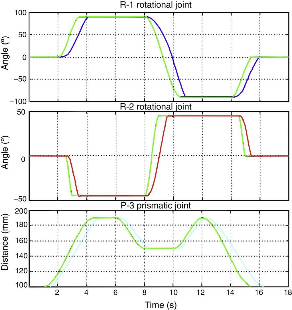
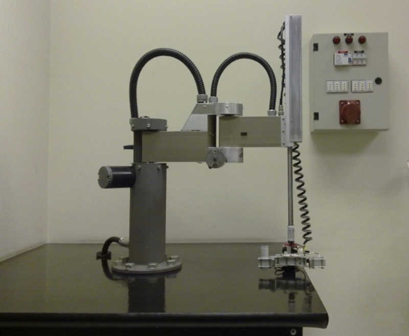
Figure 22 shows a picture of the implemented robot.
7. Conclusions
A SCARA manipulator with 6 DOF was designed and implemented, and it now constitutes a physical platform on which a variety of control techniques can be tested and studied.
The development of the PC-Controller's software, which is the same as the electronic interface, despite the complexity of its design and implementation, allowed an optimum functioning of the complete system. This software, among other functions, also enables the generation of multiple trajectories for the robot.
Mechanical, electronic, and control systems could be integrated satisfactorily, yielding excellent results, materialized in a robot.
The morphology chosen for the design and implementation of the robot allowed for carrying out numerous demonstrations and tasks, which were programmed simply and rapidly from an intuitive graphic interface created especially for that purpose.

