


 nueva página del texto (beta)
 Inglés (pdf)
 Artículo en XML
 Referencias del artículo
 Enviar artículo por email
 Citado por SciELO
  Similares en
SciELO
Similares en
SciELO 
 Permalink
1. Introduction
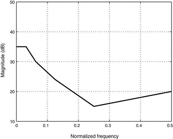
Digital hearing aid improves the quality of hearing in patients with hearing losses. An important unit of a digital hearing aid consists of digital filters that can tune the amplitudes selectively according to a person's pattern of hearing loss. Measurement of the minimum sound (in decibel) in discrete units in the range 250 Hz to 8000 Hz is plotted in an audiogram. From the readings of the audiogram, an audiologist interprets the hearing loss to be mild, moderate, profound and severe according to the range within which the augiogram falls. The sound signal is divided by the digital filters into subbands so that selective gain can be provided to each band to match the audiogram of that person. The difference between audiogram and total response of the subbands is known as matching error and is used as a quality measure of the filter design. A sample audiogram is shown in Fig. 1.
Portable systems, such as hearing aids, are often required to limit their power consumption that leads to heating up of the system. Power dissipation also affects the battery life of such systems. In a digital hearing aid scenario, this fact is largely relevant since it may cause trouble to the patient and for the inside the ear systems, which might further damage the hearing. To have lower power dissipation, one of the criteria is low hardware complexity. Thus, lowering the number of multipliers and adders also provides a major contribution. Multipliers contribute to the major share of power dissipation and area consumed in a device. Even though word-length is an important factor in determining the power consumption, multiplier-less designs provide a reasonable advantage.
There are various approaches to design digital hearing aid filters in the literature. Non-uniform subband design is better suited than uniform filter banks, since human perception is in logarithmic scale. To match using uniform filter bank would require more number of subbands, which increases the hardware complexity and cost. In one approach, an 8-band non-uniform FIR digital filter bank is realized using frequency response masking technique with two prototype filters and half band masking filters (Lian & Wei, 2005), whose matching errors are better compared to 8-band uniform filter bank. However, the delay introduced is large and delays more than 20 ms may hamper with lip-reading (Wei & Lian, 2006). This problem is addressed by using 16 bands by Wei et al., but with three prototype filters. Still, the design cost would be more for the filters with their cascade and parallel placements. An approach using variable filter-bank (VFB) that consists of three channels having separately tunable gains and band edges, is considered by Tian-Bo (2010). The method has increased flexibility, but the use of infinite impulse response (IIR) digital filters introduces overall non-linear phase to the system. Wei and Liu (2011) gives a flexible and computationally efficient digital finite impulse response (FIR) filter bank based on frequency response masking (FRM) and coefficient decimation. The frequency range is divided into three sections and each section has three alternative subband distribution schemes. The decision on selecting the sections for each subband for the selected audiogram has to be made wisely and the flexibility of the system is limited by this selection. Sample rate conversion technique to alter the bandwidth of a fixed filter, which is reused as subbands was suggested by George and Elias (2014). Bandwidth is then changed by modifying the bandwidth ratio, given as input to an interpolation filter. However, the hardware complexity of the structure is seen to be high. A non-uniform cosine modulated filter bank derived by merging technique is used for hearing aid application by Kalathil and Elias (2015), but has a restriction on the bandwidths that can be generated.
In this paper, a technique proposed by us in Haridas and Elias (2015b) is used. A variable bandwidth (VBW) filter, whose bandwidth can be varied dynamically, is implemented using Farrow structure. A filter designed using Farrow structure is proved to result in much lower number of multipliers and hence hardware complexity when compared to that of conventional FIR structure (Haridas & Elias, 2015b). All the required bandwidths for the set of selected audiograms are derived from the VBW filter. These are then shifted to the optimum center frequencies that form the subbands. This results in a digital hearing aid that is programmable and efficient (Haridas & Elias, 2015a, 2015b). All the previous techniques try to design filters that can match a single audiogram at a time while our method designs a digital filter that can cater to a set of audiograms simultaneously. This helps to lower the cost of the instrument without compromising on the quality, due to the fact that it can now be manufactured on a large scale.
The multiplier-less hearing aid designs with VBW filter and implemented using Farrow structure have not been done so far in the literature, but it is important due to the above-mentioned reasons and is the main focus of this paper. The underlying principle is that, by representing the filter coefficients in the signed power of two (SPT) space, the multipliers can be replaced with less complex and less power consuming adders and shifters (Lim, Yang, Li, & Song, 1999). A special case of the SPT space, that uses a minimum number of non-zero SPT terms, is used here, known as canonic signed digit (CSD) representation (Hartley, 1996). However, when the continuous coefficients are rounded to finite precision values using restricted number of SPT terms, characteristics of the filter degrades. Thus, a proper optimization is to be performed to enhance the characteristics. Metaheuristic algorithms are used here since the search space contains integers. Various metaheuristic algorithms are compared for the current scenario. In each case, optimization problem, in the CSD space, is solved, using the integer indices of a look-up table entries. The strength of hybrid evolutionary algorithms is also compared for the hearing aid application. The latest techniques (George & Elias, 2014; Kalathil & Elias, 2015) are compared for hardware complexity and matching error, in this paper.
The rest of the paper is organized as follows. Section 2 introduces the variable bandwidth filter design using Farrow structure. Section 3 discusses the proposed design methodology for a multiplier-less filter design with a brief overview of encoding and hybrid evolutionary algorithm. Section 4 gives design examples that verifies and compares the proposed technique with the existing techniques and Section 5 concludes the paper.
2. Variable bandwidth filter using Farrow structure
The subbands of the digital hearing aid is derived from a single variable bandwidth filter design. Of the various existing approaches discussed in the introduction, Farrow structure based variable bandwidth filter is used in the design of the multiplier-less hearing aid in this paper. A brief on Farrow structure and its design modification, that renders bandwidth variability is discussed in the following sections.
2.1. Farrow structure - an overview
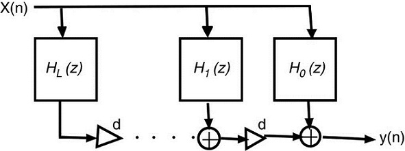
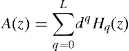
The Farrow structure was initially derived as a digital delay element, where the desired impulse response is approximated using (L + 1) th - order polynomials of a delay parameter, d (Farrow, 1988). Later, modified Farrow structure was proposed in Vesma and Saramäki (1997), where the subfilters are designed to have linear phase (symmetric coefficients), which also reduces the overall implementation complexity. It is realized as a weighted linear combination of fixed subfilters which are made variable by means of an adjustable parameter. The linear phase FIR subfilters of the Farrow structure is shown in Fig. 2. The corresponding transfer function is given as follows:

 (1)
(1)
2.2. Variable bandwidth filter
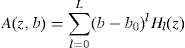
The FIR filters are designed using the Parks-McClellan algorithm for a set of evenly spaced bandwidths within the tunable range, which is then interpolated by an Lth degree polynomial in b , denoting the bandwidth. The variability is achieved by updating the adjustable parameters, which directly depend on the bandwidth. When the multipliers in this structure are quantized, it results in high overall implementation complexity due to the roundoff noise. This could be overcome by adopting a fixed parameter, b 0 (Johansson & Löwenborg, 2004; Löwenborg & Johansson, 2006), along with the variable bandwidth factor, b . The fixed parameter is selected as the mid-point between the desired bandwidths. Thus, the approximate transfer function is written as function of z and b as given below.
 (2)
(2)
where H l (z ) are Nl th order linear phase FIR subfilters (Löwenborg & Johansson, 2006). The error function is defined as the difference between the ideal and approximate frequency responses, A ideal (z , b ) and A (z , b ) respectively and is given by the following equation:
 (3a)
(3a)
where the frequency response, A ideal (e jωT, b ), whose corresponding transfer function for z = e jω is A ideal (z , b ), can be defined as follows:
 (3b)
(3b)
One of the techniques to minimize the squared error, which is widely used along with weights to emphasize certain frequencies, is the weighted least squares design approach. If it is desired to minimize the peak approximation error, it is suitable to use the minimax design. These approximation problems can usually be solved only by iterative techniques, such as linear programming.
The required filter specifications can be stated as the following:
 (4)
(4)
where b ∈ [b l, b u ] is the range of the bandwidths that can be designed. Δ(b ) is half of the transition width. Hence, b − Δ(b ) to b + Δ(b ) is the range of transition bandwidths for each of the value in b . δ c and δ s are the passband ripple and stopband attenuation respectively. The weighted error function is given by,
 (5)
(5)
where W (ωT , b ) is unity for passband and ratio of specified ripples (δ c /δ s ) for stopband. This approximation problem can be solved to have global optimum solution in the minimax sense using linear programming Löwenborg and Johansson (2006). The frequency range and required bandwidths are discretized initially and the problem is restated as
 (6)
(6)
where i , j are the discrete points used for optimization.
3. Proposed methodology using multiplier-less variable bandwidth filter
The aim of the current work is to design a hearing aid that is lighter and has a lesser power dissipation. Multipliers are known to be the power consuming part of any hardware and if they could be replaced by adders, which consume lesser area and power, the overall power consumption and size of the hearing aid can be reduced.
3.1. Canonic signed digit representation of continuous VBW filter
The CSD representation uses a digit set that is ternary and each digit may be either −1, 0, or +l. Adjacent CSD digits are never both non-zero, i.e., b i−1 × b i = 0. This property implies that for an n -bit number, there are at most n /2 non-zero digits. Any infinite precision multiplier coefficient c can be represented using the CSD format as follows:
 (7)
(7)
where l is the word length of the CSD number and the integer R represents a radix point in the range 0 < R < L . Besides, bi ∈ (−1, 0, 1). Hence, by CSD representation, multipliers can be replaced by shifters and adders (Bindiya & Elias, 2012). The number of partial product adders can be decided by the number of non-zero bits in the filter coefficient representation. Hence, reducing the number of non-zero bits in the filter coefficient representation, will reduce the number of adders. CSD is a unique representation for a given filter coefficient, with minimum number of non-zero bits (Hartley, 1996).
3.1.1. Encoding variables in the CSD space
Initially, a look-up-table with four fields, which are, index, CSD numbers, decimal equivalent and the number of non-zero SPT terms, is created. For a given set of continuous coefficients, corresponding CSD equivalent is extracted. For the multiplier-less design example in this paper, an 18-bit CSD representation, with initial 5 bits as unsigned exponent, is selected to represent a coefficient. Only the remaining is available for precision in the fractional part. A typical entry of the look-up-table is shown in Table 1.
3.2. Metaheuristic optimization
The performance of the filter degrades due to the conversion of its coefficients into CSD space. Hence, using a metaheuristic algorithm, the required characteristics of the filter are to be optimized. These characteristics are derived from the prospective solution set and expressed as the fitness function that needs to be optimized using the algorithm.
Two most important characteristics are passband ripple and stopband attenuation of the VBW filter. For each iteration, maximum passband ripple and maximum stopband attenuation are observed considering all the bandwidths that a VBW filter realizes. Thus, these are included as two of the terms in the fitness function. The stopband and passband errors are obtained from the frequency response of a VBW filter as follows:
 (8)
(8)
where,
 (9)
(9)
The term 'b' includes all the variable bandwidths that the designed filter can realize.
It is also required to reduce the number of non-zero signed power of two terms, that leads to the total number of adders required to implement the filter. If n (x ) denotes the average number of non-zero SPT terms in the filter coefficients, the final fitness function turns out as follows:
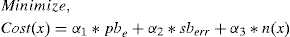 (10)
(10)
where α 1 , α 2 and α 3 denote the positive weighing coefficients that are assigned values according to the importance of the corresponding terms in the fitness function. They can be obtained by trial and error method such that the desired characteristics are obtained.
3.2.1. Evolutionary algorithms
Half the number of CSD represented coefficients of the subfilters are concatenated to form the initial seed of the optimization problem since the filters are designed to have linear phase. Thus, the length of a single individual solution of the optimization problem reduces. The filter coefficients are encoded as the signed indices of the look-up table entries of the nearest CSD equivalent. Since in the current situation, the search space includes integers, classical gradient-based optimization techniques cannot be used (Bindiya & Elias, 2012; Manoj & Elias, 2012; Manuel & Elias, 2013). Hence, in this paper, metaheuristic algorithms are chosen for the optimization, which can provide an optimal or near optimal solution.
Metaheuristics are strategies that guide a search process and the type of metaheuristic algorithms which has a learning process during the search, are often classified as evolutionary algorithms. The basic principle of many variants of evolutionary algorithm is that, given a set of possible solutions, that comprises the population, the process of natural selection retains the individuals with best fit. This improves fitness of the population in the next generation. The process is iterated until a reasonable solution is obtained or when the specified number of computations are reached. An overview of various algorithms used in this paper are given below.
Artificial Bee Colony (ABC) algorithm . A population and swarm intelligence based optimization was introduced by Karaboga (2005) for optimizing multi-variable and multi-modal numerical functions.
This model that leads to the emergence of the collective intelligence of honey bee swarms consists of three essential components: food sources, employed foragers and unemployed foragers. Food sources are selected by evaluating parameters such as closeness, richness of food source and taste, easiness of extracting food by forager bees. An employed forager is employed at current food source and gets and shares the information about the food source. An unemployed forager is of two types. It tries to find a new food source by either randomly or by means of the information given by the employed bee. Former is called a scout and latter, an onlooker.
Two of the most important honeybee colony behaviour is recruitment to a food source and abandonment of a source. Exchange of information among bees related to the quality of food sources takes place with the help of waggle dance. The bees watch numerous dances on the dance floor of the hive and choose to employ themselves at the most profitable source. The sharing of this information and hence the recruitment is proportional to the profitability of a food source. After finding the food source, the bees memorize the location and extract food (nectar) from it, turning into employed foragers. The foraging bee takes a load of nectar from the source and returns to the hive, unloading the nectar to a food store. After unloading the food, the bee has the following options:
i. It stops going to the food source. It then becomes a scout and finds a new food source.
ii. It might dance and recruit more bees before returning to the same food source.
iii. It might continue to forage at the food source without recruiting bees.
It is important to note that not all bees start foraging simultaneously. The experiments confirm that new bees begin foraging at a rate proportional to the difference between the eventual total number of bees and the number of bees presently foraging.
In a cycle, after all employed bees and onlooker bees complete their searches, the algorithm checks to see if there is any exhausted source to be abandoned. In order to decide if a source is to be abandoned, the counters which have been updated during search are used. If the value of the counter is greater than the control parameter of the ABC algorithm, known as the "limit", then the source associated with this counter is assumed to be exhausted and is abandoned. The food source abandoned by its bee is replaced with a new food source discovered by the scout.
Gravitational search algorithm (GSA) . It is based on the law of gravity and mass interactions. Search agents are objects having some specific masses that attract each other by force of gravity. Global movement of objects is towards the objects with heavier mass, which corresponds to good solution. It moves slower that other objects, due to its inertial mass and ensures the exploitation step of the algorithm. Thus, the fitness of agents is evaluated based on mass and velocity. Gravitational constant, G (t ), best (t ), worst (t ) of fitness values and agents' position are updated after sorting the population according to their fitness values, at the end of each iteration.

where α - user defined constant and T - maximum no. of iteration. GSA algorithm is modified to be used for the optimization in the discrete space in Bindiya and Elias (2012). The iteration is continued until the termination criteria is reached.
Harmony search algorithm (HSA) . It is derived based on the musical process of searching for a perfect state of harmony, that is attained by a musician through improvisation (Lee & Geem, 2005). Musician is the decision variable and referred sound pitches are preferred values of each variable.
A good harmony is stored in Harmony memory (HM). Perturbations to the initial harmony vector gives rise to different solutions. An integer multiple of harmony memory size (HMS) is selected initially for better search prospects. The HMS number of solutions are passed on to the next stage after calculating the fitness function. 'Improvisation' increases the possibility for good harmony. Harmony improvisation is based on the following steps:
* Pitch Adjusting Rate (PAR)
* Harmony Memory Considering Rate (HMCR)
HMCR is the probability of creating new vector and lies in the range, 0 ≤ hmcr ≤ 1. The process is continued until termination criteria are satisfied.
Differential evolution algorithm (DE). The DE algorithm is a simple evolutionary algorithm and is introduced by Storn and Price (1997). Here, a new offspring is generated by adjusting the existing vectors using a scaled differential operator. A population of size N is generated by randomly perturbing the initial vector. Selection of individuals with better fitness is replaced with the one with lower fitness in the next generation. The variation method as in a genetic algorithm, such as, crossover and mutation are also part of the algorithm. DE generates new parameter vectors by adding the weighted difference between two population vectors to a third vector. This operation is called mutation and is the new vector vi is given by as,
 (11)
(11)
where xi are the input population for i = 1, 2, . . ., N. r1, r2, r3 ∈ 1, 2, . . ., N are indices of input selected in random and F is the scaling factor ∈ [0, 2] which controls the amplification of the differential variation. In order to increase the diversity of the perturbed parameter vectors, crossover is performed with CR as the crossover ratio.
3.3. Hybrid techniques
Certain characteristics of two algorithms can be combined to make the filter performance even better. The population size is divided into two halves at the beginning of every hybrid iteration. The division of population size can be customized, in a manner so as to have different population sizes for each of the participating evolutionary algorithms. In a single hybrid iteration, the two algorithms run sequentially on the divided population. The fitness is calculated on each population subset and the best of two subsets are combined and randomly re-distributed to the two algorithms involved in the next hybrid iteration. The best solution of the hybrid algorithm can be replaced by the best solution in the current population, for each iteration. The hybrid algorithm used in this paper, is depicted as flow chart in Fig. 4.

The parameters for the all the optimization algorithms used in this application is given in Table 2.
4. Design examples
Three examples are given in this section. Example 1 compares the number of multipliers required for VBW filter (Haridas & Elias, 2015b) with that of the cosine modulated filter banks (CMFBs) (Kalathil & Elias, 2015), for the design of hearing aid for one audiogram. Example 2 covers the design of VBW filters for all the audiograms considered in Kalathil and Elias (2015) simultaneously. Example 3 designs the hearing aid filters of Example 1 without multipliers. All the simulations are done using MATLAB R2013b on an Intel(R) Xeon(R) CPU E5-1620 x64-based processor operating at 3.70 GHz.
4.1. Example 1: Comparison of design of VBW filter with CMFB for single audiogram
Non-uniform cosine modulated filter banks are designed for various types of audiograms in Kalathil and Elias (2015). Here, simple and efficient near perfect reconstruction (NPR) non-uniform cosine modulated filter banks with integer sampling factors are designed by merging the adjacent channels of a uniform CMFB (Lee & Lee, 1995).
To verify the VBW filter method, the matching error and hardware complexity are compared for the audiogram shown in Fig. 1. The selected audiogram for comparison is of the type, mild to moderate hearing loss at low frequencies. For the purpose of comparison, the bandwidths and filter characteristics are maintained the same as those used for CMFB based design in Kalathil and Elias (2015). In the 8-channel uniform CMFB filter bank, they have merged two pairs of bands to obtain 6 non-uniform subbands as shown in Fig. 5(a). The filter parameters and passband edges are as shown in Table 3. The procedure followed to maintain constant parameters while designing for comparison is shown in Fig. 5. Initially, the best match obtained for the audiogram, mild to moderate hearing loss at all frequencies, using 6 band non-uniform CMFB is taken as in Fig. 5(a) Kalathil and Elias (2015). The bandwidths used to obtain this kind of matching is implemented using the Farrow structure based VBW filter, whose response is shown in Fig. 5(b). Shifts and magnitude gain to the frequency bands are given as in Fig. 5(a). The difference between the response obtained in Fig. 5(c) and the audiogram, gives the matching error, as shown in Fig. 5(d).

Table 3 Filter parameters.
| Passband ripple | Stopband attenuation | Passband edges (Hz) |
|---|---|---|
| 0.001 dB | −65 dB | 828.2, 1656.3 |
A 6-subband realization is used to match the given audiogram, for both the methods. It takes 8 filters to be physically implemented in the case of CMFB, due to the merging technique. Total number of multipliers to implement the filter bank is thus eight times that required for the prototype filter. To obtain 6 bands, on the other hand, the VBW filter method requires only 6 filters to be implemented physically, as bank of filters, each having pre-tuned bandwidths of the VBW filter. Thus, the total hardware requirement in terms of multipliers is six times of that required for a VBW filter. This is compared in Table 4, along with the matching error. Total delay experienced due to the filter is estimated to be as low as 1.1 ms and is shown in Table 4. The delay is contributed by two Farrow subfilters of order 35 each, that process the signal in parallel and a single multiplication of b − b 0 . The delay is calculated as 18/16, 000, where 16 kHz is the sampling frequency. It can be observed from Table 4, that a smaller number of multipliers without compromising on the performance of the hearing aid, can be achieved using our design.
Table 4 Comparison of hardware complexity and error.
| No. of bands | Total no. of multipliers | Matching error (dB) | Delay (ms) | |
|---|---|---|---|---|
| CMFB (Kalathil & Elias, 2015) | 6 | 31 × 8 =248 | 2.19 | 1.9 |
| Proposed method | 6 | 34 × 6 =204 | 2.10 | 1.1 |
Similarly, it can be noted from Table 5 that with a different set of bandwidths and spectral shifting of the selected subbands to match the same audiogram, better results are obtained using VBW filter using Farrow structure. The design specifications of the first row gives better matching error with reasonable number of multipliers and those of second row lead to a much higher saving of hardware. More than 100 multipliers are saved in the design as in the second row when compared to the design in Kalathil and Elias (2015), keeping the matching error minimum and with lower delay.
4.2. Example 2: Comparison of designs for all audiograms in Kalathil and Elias (2015)
The design followed in this paper, Haridas and Elias (2015b) is advantageous when done simultaneously, as against any other method considered in this regard. A comparison of this design for all the example audiograms in Kalathil and Elias (2015), is made in this example. The selected audiograms are given in Fig. 6. The variable bandwidth filter designed in this case can realise two bandwidths, 1000 Hz and 1500 Hz variably, which implements it with 36 multipliers. Table 6 gives the number of channels required using our design, as compared to the merged channels of CMFB.

Table 6 Comparison for various audiograms for hardware complexity and matching error.
| Type of hearing loss | Non-uniform CMFB - merging | Our methodc | ||||||
|---|---|---|---|---|---|---|---|---|
| No. of bands | Total multsd | M Ea | Delay (ms) | No. of bands | Total multsd | M Ea | Delay (ms) | |
| Mild to moderate HLb at low frequencies | 8 → 6 | 248 | 2.19 | 1.9 | 6 | 216 | 1.67 | 1.1 |
| Mild HLb at all frequencies | 16 → 9 | 768 | 2.15 | 3 | 6 | 216 | 2.11 | 1.1 |
| Moderate HLb at high frequencies | 28 → 16 | 2464 | 2.49 | 5.5 | 6 | 216 | 2.45 | 1.1 |
| Mild HLb (left ear) | 28 → 10 | 2016 | 2.38 | 4.5 | 6 | 216 | 2.07 | 1.1 |
| Mild HLb (right ear) | 24 → 11 | 1728 | 2.4 | 4.5 | 6 | 216 | 2.13 | 1.1 |
a ME - matching error.
b HL - hearing loss.
c Our method - Haridas and Elias (2015b).
d Total number of multipliers.
The entry such as 8 → 6 for CMFB, denote that the number of filters to be implemented is 8 whereas only 6 subbands are present. The matching errors are seen to be lower in our case and are depicted in Fig. 7.

Total number of multipliers for 6 bands for all the audiograms designed simultaneously is 216 which is lower than the corresponding number of multipliers to implement CMFB, as seen from Table 6. The VBW filter is made of six subfilters of order 36 each. As in Example 1, the total delay estimate is only 1.1 ms. Delay incurred by the CMFB based design for each of the audiograms are provided in Table 6. The same filter is thus sufficient to be used for all the types of audiograms considered in this example, whereas, a different set of prototype filters and varied number of subbands are required for CMFB based design. This shows the reduction in design complexity also, as far as our design is concerned.
Example 3: multiplier-less design
In the previous examples, the Farrow based VBW filter is proved to be efficient compared to the CMFB based design for hearing aid. In the same manner, a comparison is done with that of Haridas and Elias (2015b) and is seen to give better results. In this example, the Farrow VBW designed for the audiograms in Haridas and Elias (2015b), as given in Fig. 8, is made multiplier-less using the technique proposed in this paper. The audiograms considered in this example cover almost all ranges of hearing loss patterns.

The filter specifications chosen for the VBW design and which are obtained using Farrow VBW design are as follows:
To get a minimum matching error with the considered audiograms and lowest possible order of the VBW filter, different number of subbands are investigated. Number of hearing aid subbands tried in this experiment are 10, 8, 6 and 4. For each of these, a different VBW filter design as explained in Section 2.2, is carried out for the bandwidths as given in Table 7a. The transition width in each case and thus the total order of a single filter are also mentioned. The total order is thus the number of subbands multiplied by the order of a single filter. The matching errors using continuous coefficient representation of the subband filters, for all the considered audiograms, are provided in Table 7b.
Table 7 Hardware complexity and matching error of proposed method.
| (a) VBW parameters with 10, 8, 6 and 4-band hearing aid for audiograms | |||
|---|---|---|---|
| No. of bands | Bandwidths (Hz) | Transition width (Hz) | Order of 1 VBW filter |
| 10 | 500, 750, 1000 | 955.52 | 60 |
| 8 | 800, 1000, 1500, 1900, 2500, 3160 | 1244.4 | 147 |
| 6 | 800, 1000, 1600, 2000, 2400, 2800,3700 | 1357.5 | 138 |
| 4 | 1000, 1800, 3000, 5000 | 1991 | 84 |
| (b) Comparison of minimum matching errors with 10, 8, 6 and 4-band hearing aid for various audiograms | |||||
|---|---|---|---|---|---|
| Sl. no. | Type of hearing loss | Number of bands and maximum matching error in dB | |||
| 10 | 8 | 6 | 4 | ||
| 1 | Mild to moderate hearing loss at low frequencies | 1.49 | 1.18 | 1.51 | 2.09 |
| 2 | Mild hearing loss at all frequencies | 1.22 | 1.26 | 1.61 | 1.99 |
| 3 | Mild hearing loss at high frequencies | 1.81 | 2.02 | 2.03 | 2.71 |
| 4 | Moderate hearing loss at high frequencies | 1.85 | 1.97 | 2.60 | 3.09 |
| 5 | Profound hearing loss | 1.76 | 2.67 | 2.87 | 2.89 |
| 6 | Severe hearing loss in the mid to high frequencies | 2.49 | 2.44 | 2.96 | 3.99 |
From Table 7, the design corresponding to 6 subbands is selected. None of the matching errors, in this case is greater than 3 dB and the number of multipliers to implement this is 138. In this VBW filter design, half of the subfilter order is 21 and hence the total delay incurred with six subfilters is approximately 1.3 ms. Two of the notable references in audiogram matching are Huang, Tian, Ma, and Wei (2015) , Wei and Liu (2013). The first one Wei and Liu (2013), uses a multiband-generation block to generate different bands and a subband-selection block to select the required ones by means of masking. A large amount of delay is incurred in this case, as number of stages is more. The second one Huang et al. (2015), uses cosine modulated filter bank to realize uniform bands and then applies transformation technique to convert them to non-uniform subbands. Here, a filterbank to match three audiograms simultaneously are designed. A comparison of 2 common audiograms in these methods with our design is done in Table 8 in terms of matching error and delay.
Table 8 Comparison of proposed method with other methods in literature.
| (a) Comparison for Mild hearing loss at all frequencies | |||
|---|---|---|---|
| Method | No. of bands | Matching error (dB) | Delay (ms) |
| Method I Wei and Liu (2013) | 8 | 4.82 | 29 |
| Method II Huang et al. (2015) | 28 | 1.35 | 7.7 |
| Proposed design | 6 | 1.61 | 1.3 |
| (b) Comparison for Mild hearing loss at high frequencies | |||
|---|---|---|---|
| Method | No. of bands | Matching error (dB) | Delay (ms) |
| Method I Wei and Liu (2013) | 7 | 2.67 | 25 |
| Method II Huang et al. (2015) | 28 | 3.75 | 7.7 |
| Proposed design | 6 | 2.03 | 1.3 |
The canonic signed digit representation of the designed continuous coefficient filter, converts the multipliers in the implementation to adders and shifters. The number of adders in the design relates to the number of signed power of two (SPT) terms, which are 1 and −1. In the current scenario, the value of Farrow subfilter coefficients has a maximum range of 11 (in terms of base 10), which requires 5 CSD bits before the binary point. Hence, for 18-bit CSD, 5 bits are in range and 13 bits contribute to the resolution (precision). Characteristics of the filter designed using filters represented with 16 and 18 bit CSD and for varying number of SPT terms are given in Table 9. The maximum precision representation for 16 bit CSD (8 SPT) attains a maximum stopband attenuation of −47.08 dB only. Thus, better characteristics are obtained when 18 bit CSD is used. Coefficients of the filters having specifications as in the second last row of Table 9 are thus taken as initial values for optimization.
Table 9 Selection of number of bits in CSD representation.
| CSD | Max SPT | Pb rip a (dB) | Sb attn.b (dB) | No. of adders |
|---|---|---|---|---|
| 16 | 8 | 0.0804 | −47.08 | 347 |
| 7 | 0.0804 | −47.08 | 347 | |
| 6 | 0.0801 | −47.15 | 344 | |
| 5 | 0.0774 | −48.62 | 333 | |
| 4 | 0.1122 | −36.59 | 301 | |
| 18 | 9 | 0.0729 | −62.01 | 436 |
| 8 | 0.0729 | −62.01 | 436 | |
| 7 | 0.0729 | −62.01 | 436 | |
| 6 | 0.0719 | −61.46 | 428 | |
| 5 | 0.0678 | −56.46 | 401 | |
| 4 | 0.1157 | −39.19 | 354 |
a Pb rip - passband ripple.
b Sb attn. - stopband attenuation.
The degradation of the characteristics is restored using metaheuristic algorithms as explained in Section 3.2. The cost function is given as per Eq. (10). The resultant characteristics due to various single and hybrid techniques are enlisted in Table 10. It should be noted that the matching error is not affected by changing the coefficients. Thus, the total number of adders can be brought down without affecting the digital hearing aid performance.
Table 10 Optimized characteristics using various algorithms.
| Algorithm | No. of iterations | α 1 | α 2 | α 3 | Pb | Sb | Adder | CPU time (s) |
|---|---|---|---|---|---|---|---|---|
| ABC | 500 | 0.05 | 35 | 0.03 | 0.0772 | −64.24 | 439 | 1153.90 |
| GSA | 500 | 0.01 | 20 | 0.02 | 0.0801 | −65.13 | 425 | 1122.80 |
| HSA | 500 | 0.3 | 30 | 0.001 | 0.0725 | −60.28 | 438 | 349.33 |
| DE | 500 | 0.05 | 30 | 0.05 | 0.0663 | −60.82 | 436 | 593.2 |
| ABC-GSA | 500 | 0.05 | 25 | 0.08 | 0.0689 | −64.58 | 426 | 13,747.45 |
| ABC-HSA | 100 | 0.02 | 25 | 0.01 | 0.0737 | −62.39 | 441 | 14,607.50 |
| ABC-DE | 500 | 0.2 | 25 | 0.001 | 0.0753 | −63.62 | 437 | 10,021.80 |
| GSA-HSA | 500 | 0.01 | 30 | 0.02 | 0.0778 | −65.30 | 437 | 46,969.0 |
| GSA-DE | 500 | 0.05 | 22 | 0.02 | 0.0724 | −65.38 | 426 | 14,041.46 |
| DE-HSA | 500 | 0.002 | 35 | 0.001 | 0.0739 | −64.93 | 439 | 26,467.30 |
The performance of GSA-DE algorithm is seen to be the best among the various optimization algorithms, in this case. It shows better stopband attenuation as well as lower number of adders. Almost −3 dB better than the maximum precision characteristics is obtained with as much as 14 adders less. In the final design, only 426 adders are required in place of 138 multipliers and 275 adders.
4.3.1. Hardware Implementation
To emphasize the extent of low hardware complexity in the structure, it is implemented in a field programmable gate array (FPGA) and information on complexity parameters such as area and power are extracted. For this purpose Xilinx Kintex 7 Xc7k480t FPGA is used. The VBW filter using continuous coefficients and CSD represented coefficients are coded using verilog and simulated using Xilinx ISE Design Suite 13.2. The leakage power is calculated using XPower Analyzer. The register transfer level (RTL) schematic obtained after synthesis is given in Fig. 9. It consists of 7 Farrow subfilters designed using FIR filter structure and a delay module that performs bandwidth variation using the factor b , as shown in Fig. 3. The observed values are for a single band, out of the 6 subbands required for matching the selected set of audiograms. Area and power requirements for both the cases are as shown in Table 11.

Fig. 9 Farrow VBW filter implemented using CSD coefficients using shift and add operations on Xilinx ISE Design Suite 13.2.
Table 11 Hardware implementation complexity analysis.
| Multipliers | Adders | Area | Power (W) | ||
|---|---|---|---|---|---|
| Slice registers | Slice LUTs | ||||
| Cont. coeff.a | 138 | 275 | 4211 | 85,290 | 0.555 |
| Opt. CSDb | - | 426 | 876 | 10,784 | 0.496 |
a Continuous coefficients.
b Optimized CSd coefficients.
It can be observed that the number of slice registers and look-up-table (LUTs) have reduced substantially for the optimized design without multipliers. The power dissipation shown in Table 11, is mostly due to leakage power. As the hearing aid works at 16 kHz clock frequency, the dynamic power incurred is negligible. Thus, only small difference in power dissipation is observed between the two methods shown in Table 11.
5. Conclusion
Low-complexity design of hearing aids using Farrow based variable bandwidth filter is proposed in this paper. Multipliers are expensive units of hardware in terms of area they occupy and the power dissipated. In the design of digital hearing aid proposed in this paper, the multipliers of the reconfigurable filter are reduced to adders and shifters by CSD representation of its coefficients. Meta-heuristic optimization algorithms are used to improve the characteristics of this filter. It is observed from the example that the implementation complexity in terms of number of LUTs required, is reduced by four times. This paper also projects the power of hybrid optimization algorithm. Thus, this paper has two major contributions. The first one is the use of Farrow structures as VBW filter in a digital hearing aid for audiogram matching, which leads to less number of multipliers when compared to that using conventional FIR filters and filter banks. Secondly, the filter is made multiplier-less using CSD technique and the performance is improved using meta-heuristic algorithms. Hybrid GSA-DE algorithm improves all the selected characteristics of the filter, including the number of adders, compared to those obtained with GSA and DE algorithms individually. Further, the VBW Farrow filter based design supplements the total complexity reduction by efficient matching with lower number of subbands. Also, this kind of design is reusable for all the set of audiograms for which it is designed, unlike the existing techniques, which require one set of filters for each audiogram to give the least matching error.

