


 nova página do texto(beta)
 Inglês (pdf)
 Artigo em XML
 Referências do artigo
 Enviar este artigo por email
 Citado por SciELO
  Similares em
SciELO
Similares em
SciELO 
 Permalink
1. Introduction
Terahertz antennas (lithographic antennas) are devices which had opened a new route for the sensing and manipulation of the mid-infrared electromagnetic radiation free in the space, founding in last years applications in the field of infrared image acquisition (Gonzalez, Ilic, Alda, & Boreman, 2005) and solar energy harvesting (Briones, Alda, & González, 2013). Terahertz antennas work by using the wave nature of the THz radiation in order to induce a resonant alternate current along the antennas arms (with the same frequency of the incoming wave) which is exploited to sense or recover the optical energy of radiation.
In imagining applications, these types of antennas have been coupled with success to niobium microbolometers to capture images with infrared cameras containing hundreds of these elements (González, Gritz, Fumeaux, & Boreman, 2002). The presence of current in antennas heats the microbolometers loaded to them, leading to an increase of its temperature what in turns changes the resistance of bolometers, defining this way the detection mechanism (Codreanu, Gonzalez, & Boreman, 2003). In the field of solar energy harvesting, lithographic antennas have been used to capture radiation coming from the sun and to build solar energy panels (Bareisß et al., 2011) when coupled to THz rectifiers based on metal-oxide-metal diodes, allowing the recovering of the optical energy into Direct Current (DC) Power.
In spite of the attractive properties of the THz antennas as thermal devices, the principal reason that they have not been yet employed in commercial applications it is their low performance, arising from impedance matching or energy transfer problems between the THz antennas and the load elements; being a topic of current interest (Krenz et al., 2012; Mandviwala, Boreman, & Lail, 2008; Mandviwala, Lail, & Boreman, 2005). Some coupling methods commonly used with the radio and microwave antennas have recently been scaled to the THz regime in order to better match the diodes to the antennas. In this context, transmission lines have been used as impedance-matching elements between a thermocouple and a bow-tie antenna tuned to absorb in the mid-infrared region, obtaining a substantially increase of its response (Krenz et al., 2012). By the other hand, transmission lines have been employed with success at optical frequencies in order to transmit the optical energy from an emitting dipole to a receiving one (Huang, Feichtner, Biagioni, & Hecht, 2009), showing that the principles of classic transmission lines can be "extra-poled" to high frequencies (where metals are no longer considered as perfect conductors as classical theory of antennas does).
In this work, different types of impedance matchers as transmission line sections, open-circuit and short-circuit stubs, are considered as couplers at THz frequencies in order to improve the energy transfer between a mid-infrared receiving dipole and a niobium micro-bolometer coupled to it. The performance of the impedance matchers is evaluated from a numerical perspective by using the software COMSOL Multi-Physics 3.5a, commercial package based on the finite-element method which allows performing electromagnetic simulations.
2. Method
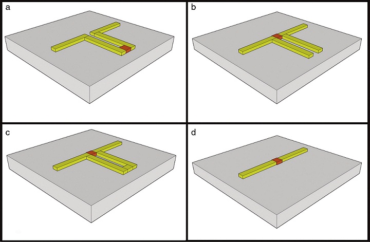
A sketch of the proposed matching structures is depicted in Fig. 1. These consist of (a) a section of transmission line of length l a with characteristic impedance Z 0 , inserted between the load element and the antenna, (b) an open-circuit stub of length l oc and (c) a short-circuit stub of length l sc , both of them in parallel at the feed point of the antenna. Case (d) corresponds to the antenna-coupled detector without impedance matching. In order to evaluate the performance of these structures, a gold dipole tuned to capture the infrared radiation at 10.6 μm was used as a proof of concept (2.9 μm long, 200 nm width and 100 nm thick) and a niobium microbolometer was used as the load element (250 nm with, 250 nm long and 100 nm thick).
The structures were placed on a semi-infinite SiO2 substrate and a 10.6 μm linearly polarized plane-wave was used for far-field illumination (with arbitrary irradiance of 117 W/cm2), with its polarization set to match that of the antenna. The numerical analysis was performed by using the software package COMSOL Multi-Physics 3.5a and the numerical model was built using all the optical properties of materials reported at 10.6 μm wavelength (Au: n = 11.72 + 70.86i , SiO2: ε r = 4.84 and Nb: ε r = 3.8, σ = 6e6 S/m (Palik, 1991).
The power in the microbolometer was measured by integrating the average resistive heating and used as measure of the energy transfer. Scattering boundary conditions were used in the FEM simulations and tetrahedral elements were used to discretize the computational domain. This process was performed considering the three cases of impedance matching structures and a sweep of physical lengths in terms of the wavelength, to determine the one that best matches impedances between the dipole and the microbolometer.
3. Results
As it was mentioned before, three different matching structures were used in this study. In case (a) the matching structure was a section of a bifilar microstrip transmission line between the antenna and the microbolometer. Case (b) was an open-circuit stub connected directly to the microbolometer. Finally case (c) a short-circuit was evaluated. All of the purposed matching structures had their transversal sections as wide as the transversal section of the dipole arms. Different lengths for the three cases were considered in order to evaluate the length that best matches the impedance between the coupled devices. Resistive heating vs the length of the structure for the three cases is showed in Fig. 2.
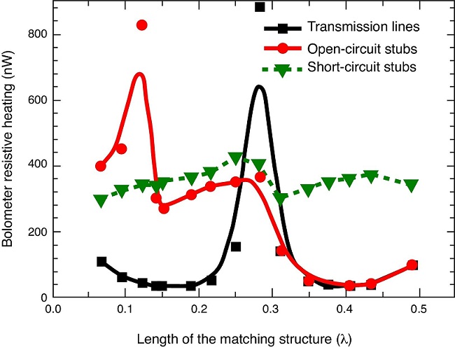
Fig. 2 Comparison of the resistive heating of three matching structures as a function of the length.
It can be noticed that cases (a) and (b) are the cases where the device response is higher. The absence of matching structure is used as a reference mark for the comparison. The case that offers better impedance matching is case (a), where a peak response of 900 nW is presented when length of the matching structure is 0.28λ , which is very similar to what the theory at microwave frequencies sets i.e. 0.25λ . Case (b) offers a maximum response of 840 nW when the length is 0.122λ ≅ λ /8, while case (c) offers a maximum response of 450 nW when the length is 0.25λ . These maximum responses of all the three matching cases are higher than the response without matching technique (250 nW). With these results it is clear that when THz radiation incides on the antenna, electrical current in induced, this electrical current causes Joule's heating. As high as the power is, as good is the antenna-coupled microbolometer response. Finally, it could be noticed by means of computer simulations that in case "a" (transmission line section) which presents the best response (0.28λ , 900 nW), the antenna input impedance is 74.16-103.46i Ω, a very close value to those presented in dipole antennas.
4. Discussion
In classical antenna and transmission line theory it is well-known that a λ /4 impedance transformer, is a component consisting of a length of transmission line or waveguide exactly one-quarter of the wavelength (λ ) long and terminated in some impedance. These matchers are used at radio frequencies of upper VHF or higher up to microwave to match impedances between transmission lines with transmitting or receiving antennas. In this work impedance matchers are purposed to match impedance between lithographic dipole antennas and microbolometers in order to ensure the maximum power transfer from the antenna to the microbolometer. It could be noticed in this work that the structure that offers a better impedance matching between lithographic dipoles and microbolometers is the one that considers the inclusion of a section of transmission line of certain length (case (a)), resulting in a length of 0.28λ which is very similar to a λ /4 impedance transformer used at lower frequencies. This 0.28λ impedance transformer improves the antenna-coupled microbolometer response by 360% compared with the case where no matchers are used. The other matching structures that offer good impedance matching (cases (b) and (c)) are the 0.122λ open-circuit and the λ /4 short-circuit stubs, offering improvements of 336% and 180% respectively. It is noteworthy that cases (a) and (b) are very similar in terms of response but different in terms of structure length (one is about double of the other).

