


 nueva página del texto (beta)
 Inglés (pdf)
 Artículo en XML
 Referencias del artículo
 Enviar artículo por email
 Citado por SciELO
  Similares en
SciELO
Similares en
SciELO 
 Permalink
Introduction
Condensation is a process of scientific and industrial importance, considered in the design of cooling towers, heat exchangers, and absorption towers. It is a process that also has drawn attention for the growth of thin films, as proposed originally by Nelson [1] and now known as liquid phase epitaxy (LPE). LPE is the growth of thin films from metallic solutions on top of an oriented surface, supplied either directly as a liquid [2-4] or formed by condensation of vapors [5]. The solvent can be a constituent of the growing solid or some other low-melting metal incorporated into the solid as a dopant. The solvent contains a small quantity of a solute (such as As in Ga), which is transported towards the liquid-solid interface by diffusive transport. Growth boats are designed such that diffusion perpendicular to the interface is promoted and convection and surface-tension-related transport are suppressed. The suppression of convective and surface tension transport is achieved by avoiding temperature gradients in the solution and ensuring that height and radius of curvature of the liquid film are small compared to the characteristic substrate length. An excellent review explaining in detail the physics behind the growth of semiconductor thin films from the liquid phase can be found in the literature [6].
When LPE is performed by condensing a vapor on a substrate heated above the melting point, many interesting phenomena arise that are not present in the case of the traditional LPE, where the liquid is applied directly to the substrate. Depending on the temperature and pressure, the vapor phase condenses either as a liquid (defined as the stable condensed phase above bulk melting point) or as a solid.
In the case of condensation and melting of materials, extensive information exists for steam and condensable hydrocarbon vapors, but for metallic and semiconductor materials, most references focus only in solid thin film growth, with scarce references regarding their vapor condensation on surfaces with a temperature above melting point. Formation of the liquid can even occur below the normal melting point due to surface melting, capillary condensation, eutectic alloying, among other phenomena [7]. This thin film formation method via condensation of vapor phase into a liquid has also been recently used in the synthesis of ultrathin ionic liquid films [8] and ZnO nanostructures [3,9]. Many unanswered questions arise in the study of this mechanism of film growth due to the vapor-liquid-solid transitions that make the phenomena really complex [10-12]. Not a lot of work has been done on a technique that can be considered a hybridization between traditional PVD (the precursor is the vapor from an evaporating solid) and LPE (the growth of the solid film arises from the liquid that condenses in the substrate).
In nuclear science, condensation studies are important because recently the nuclear fusion community is trying to use liquid metals for walls and divertor on tokamaks reactors. The main metal candidates are lithium and gallium, but some papers reports problems with the use of this kind of liquid metals. For these reasons, it is critical to study the behavior of these metals on different substrates, and study the interaction between the vapor phase and a solid substrate. Most condensation processes are assisted by the presence of a solid surface, where a liquid film can grow from the vapor phase. Since many unit operations in industry rely on condensation processes, plenty of information exist for common vapors such as steam and condensable hydrocarbon vapors [7,13,14]; for the case of these fluids, there are many analytical correlations involving dimensionless groups, such as the Reynolds, Prandtl and Grashof numbers [15]. However, due to the peculiar thermofluid properties of the molten alkali metals, they fall outside the range of validity of most of these empirical correlations. In the case of metallic vapors, most of the experimental work reported concentrates on thin solid film growth via Physical Vapor Deposition (PVD), Molecular Beam Epitaxy (MBE), and sputtering techniques, but much less references have been found regarding the condensation of metallic vapor on solid surfaces above the melting temperature [15]. For the case of alkali metals the situation is even more restricted, with most literature focusing on sodium and potassium due to their use as fast breeder nuclear reactor coolants [4,16]. In the case of metal melting, its understanding is becoming very important to optimize novel treatments like focused energy sources to repair structures [17], or Ta metal refinement using a plasma arc [18]. Some topic areas where the dynamics of condensation of metallic vapors is important, particularly alkali metals, include liquid metal cooled nuclear reactors, in particular sodium/potassium and their alloys [19,20], and magnetic fusion reactors, mainly lithium and some of its alloys [21].
In the particular case of fusion reactors with magnetic confinement, concepts have been proposed involving the implementation of a liquid divertor component in order to avoid permanent damage to the reactor. By using a flowing component, the residence time within the reactor is finite and the energy deposited in this flowing component can easily be coupled to a heat recovery scheme [22]. The transport of evaporated lithium condensed on hot surfaces above the melting point and on evaporative units designed to extract tritium from the lithium stream, are application examples for which data on the condensation dynamics of lithium in hot surfaces has great relevance [23]. The experimental facility described in this paper was tested with lithium to obtain these particular data, but its use is not restricted to this metal.
Description of the experimental facility
Vacuum chamber
Due to the temperature and pressure requirements in semiconductor growth and the reactivity of lithium and other alkali metals, this experimental device is a refined extension of the typical condensation experiments for water and hydrocarbons [24] and previous metal vapor condensation experiments [25]. For the experimental studies planned for semiconductor or metal vapor condensation, a cylindrical stainless steel vacuum chamber was designed and built, with its overall dimensions and port configuration shown in Figure 1a. The chamber is a cylinder with 40 cm height and 40 cm diameter, divided in three parts: a top-hinged lid, the cylindrical chamber body and a bottom bolted lid. The lids are attached to the main chamber by ISO flanges with an o-ring seal. The chamber assembly has a total of 28 metal-seal (Conflat) ports with four different diameters: 1.65, 3.71, 6.12 and 9.93 cm; these ports are used for attaching multiple accessories that allow viewing the interior, permit electric power and signals between the interior and exterior of the chamber, allow internal motion of components, feed gases and generate vacuum. Seventeen ports are on the cylindrical chamber body, seven in the upper chamber lid and four in the lower chamber lid. The vacuum chamber design is versatile, so it can be used for different experiments in addition to the main studies on condensation and melting, such as contact angle measurements, surface passivation by oxidation, surface roughness evolution with non-contact optical techniques, and in general, physical and chemical vapor deposition experiments.
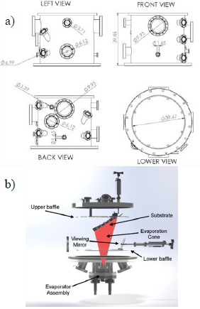
Figure 1 a) Schematic with four views of the vacuum chamber body that houses the experiment, showing the main dimensions. b) Internal view of the vacuum chamber, showing the two internal baffles and their position with respect to the evaporator assembly and the substrate holder.
The chamber has two internal stainless steel baffles to prevent deposition of metal vapors on components such as electrical connectors and/or windows, shown in Figure 1b. The lower baffle has an opening to allow substrate view from the bottom, as well as a rectangular opening calculated to collimate the vapor flux and generate an evaporation cone that will condense mainly on substrate surface. The upper baffle serves to mount the substrate as well as to protect connections.
Evaporator
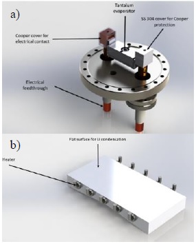
The evaporator assembly is installed on a large port at the bottom lid, as shown in Figure 2a. The main component in this assembly is an evaporation box made of tantalum sheet (model SO-24 from R.D. Mathis Co.), with internal baffles, two compartments with a volume of 22 cm3 each, and a chimney with a diameter of 1.25 cm with an area of 1 cm2 where the vapor escapes. This evaporation box can handle up to 250 A of current and reach a temperature in vacuum up to 1200 °C. The electric current to heat the box is supplied by a 3.2 kW (400 A, 8 V) DC power supply (TDK Lambda Genesys), and fed inside the chamber via two high-current copper feedthroughs capable of handling up to 600 A. The evaporator assembly has two additional ports for a thermocouple with an ungrounded sheet and a rotary feedthrough for a shutter.
Sample holder
The vacuum chamber has a rectangular substrate with a flat surface of 20 × 10 cm, made out of AISI 304 stainless steel, as shown in Figure 2b. The flat surface faces downwards in direct line of sight to the evaporator chimney; on this surface, condensation is expected to occur. In order to condense in liquid phase, the substrate must be heated to a temperature above the melting point of the condensing metal; for lithium, the metal initially to be studied in this facility, the sample holder has to be heated above 180 °C. To reach this temperature, the substrate is equipped with 10 cylindrical cartridge heaters (5 cm long, 0.6 cm diameter, 10 W/cm2 power density), arranged in 5 independent sets of 2 heaters in series, each set heating a zone of the substrate. Each heater set has its own built-in thermocouple and independent PID temperature controller, actuated by an on-off solid-state relay. Since the effect of surface temperature gradients on the condensation dynamics is also to be studied, the substrate was constructed with a V cross section, such that its mass distribution is not homogeneous, hence promoting the appearance of surface temperature gradients.
Diagnostics
Different diagnostics have been installed in the evaporation chamber to measure total pressure, temperature and residual gas composition; however, two diagnostics deserve a detailed description given their importance for the operation of the facility: the deposition monitor and the laser light scattering (LLS) diagnostic. The first is critical to measure the evaporative flux coming from the evaporator and hence estimate the amount of vapor that reaches the substrate; the LLS diagnostic allows the real time monitoring of modifications to surface roughness, homogeneity deposition and curvature radius.
The deposition monitor is based on a quartz crystal microbalance (QCM), mounted on a movable stage that allows moving the diagnostic across the opening of the evaporator. The sensor, which has an exposed area of 0.89 cm2, is located 18 cm above the lower baffle that contain the evaporator. The readout of the sensor when exposed to the vapor gives the deposition rate dx/dt, measured in Å/min. Results from the calibration of this diagnostic are presented in the following section.
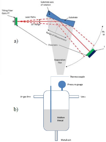
The LLS diagnostic is already built and is under calibration. The conceptual design of this diagnostic is shown in Figure 3a. A fiber optic feedthrough is mounted on a tilting stage that allows ±10° angular sweeping of a laser fed via optical fiber. Thanks to this motion, the laser can be aimed at different locations within the exposed surface, and reflected from it. The amount of scattered light will carry information about the surface, such as roughness and curvature, since scattering from metal and oxidized layers is different [26] [27]. The scattered light is collected by a linear array of detectors, which can rotate on the same axis as the sample holder; this allows the monitoring of scattered light around the main reflected beam, so information about the early stages of film formation and film surface properties can be extracted from the optical signal. If oxidized metal film is optically semitransparent in the visible range spectrum, that would give the diagnostic the ability to measure its thickness in real time [27].
Vacuum goniometer
The internal configuration of the vacuum chamber was modified in order to also make measurements of liquid metal wettability properties over different surfaces. The most common description for the wettability of a solid by a liquid is the equilibrium of a small droplet of liquid (known as a sessile) on top of a flat, homogeneous surface, with the force equilibrium described by the Young equation [28]:
where γ represents the interfacial tension and the subscript indicates its values for the solid/liquid (SL), liquid/gas (LG) and surface/gas (SG) interfaces. The angle θ is known as the contact angle, the tangent to the droplet profile at the point where the three phases (solid, liquid and gas) meet. The Young equation is obtained by minimizing the total surface free energy for a spherical/ellipsoidal cap of fluid of constant volume resting on a flat surface. The shape of the drop is given by the hydrostatic equilibrium between gravity forces and capillary forces, and can be described with the aid of the Young-Laplace equation [29]:
The expression resulting from applying the general form of the Young-Laplace equation, Equation (2), to a sessile drop geometry, results in a special case known as the Bashfroth-Adams (BA) equation. The mathematical derivation of the BA equation (which is a differential equation for the case of an axisymmetric sessile droplet) is lengthy and can be consulted elsewhere [30]; the end result is that the shape of the sessile drop is given by the BA equation, which uses the measured contact angle θ as a boundary condition for its solution. This allows the calculation of the solid/liquid interface energy when combined with Equation (1).
The vacuum goniometer configuration of the chamber, constructed to measure contact angle of liquid metals on different surfaces experimentally, consists of a cylindrical melting tank made of AISI 304 stainless steel, with a total volume of 55 cm3. It is equipped with an internal thermocouple and a vacuum gauge, as well as gas entry and evacuation ports to precisely regulate the pressure on top of the molten metal; an exit tube is placed at the bottom of the tank. The melting tank and its components are shown in Figure 3b. Since the top of the liquid is pressurized and the exit is exposed to the vacuum environment, it is possible to force the liquid out of the melting tank by simply regulating the pressure difference. It is a delicate balance, since insufficient pressure is not able to overcome the capillary force of the metal in the tube (due to the high surface tension in most metals), whereas excess pressure will result in a steady flow of metal out of the melting tank. The melting tank is heated externally using rope heaters connected to an autotransformer and wrapped in fiberglass insulation with a reflective aluminum layer to prevent heat losses.
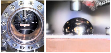
The exit end of the melting tank sits 3 cm away from a heated sample holder, made out of copper and capable of reaching temperatures up to 700 K; on top of the copper surface. The sample holder assembly is located in the middle of the field of view of a 10 cm diameter window in the chamber. Figure 4 shows a full window view and a close-up of a lithium drop deposited in the hot plate.
System performance description
In order to test and calibrate the experimental facility, some preliminary measurements on the different systems were performed, and results are described in this section: evaporator calibration, sample holder thermal behavior, and contact angle as function of temperature.
Evaporator calibration
Experiments were carried out to verify the ability to predict
and control of the evaporation rate on the system. The starting point is the
estimation of the evaporation source strength
Where P is the vapor pressure of the material evaporated, m is the atomic mass, k B is the Boltzmann constant and T is the absolute temperature. In order to use Equation (1) to estimate the evaporative flux, the functional relationship between the vapor pressure and the temperature is required. Typically, the Antoine equation is adequate to estimate vapor pressure as a function of temperature:
The Antoine coefficients A, B and C for lithium were obtained from the literature [32, 33]; they are 4.988, 7918.98 and 9.52, respectively. Substitution of Equation (4) in Equation (3) allows the calculation of the evaporative flux as a function of temperature, shown in Figure 5a for the case of lithium. Since mass is conserved, the following relationship needs to hold:
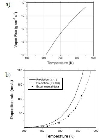
Figure 5 a) Evaporative flux
The right-hand side of Equation (5)
represents the mass flux
where
Equation (7) estimates the
deposition rate as a function of evaporator temperature, and it is contrasted
with actual measurements of deposition rate performed in the experimental setup
using the QCM diagnostic (Table 1). Power
was obtained by multiplying current and voltage from the power supply, and the
temperature was read from a thermocouple attached to the evaporator. Figure 5b shows the predictions of Equation (7) with the actual points
from Table 1, for values of
Sample holder thermal behavior
Another calibration activity on the assembled chamber was the determination of temperature profiles in the sample holder. As mentioned in the experiment description section, five independent heating zones were defined, each with one thermocouple and two heaters. The sample holder was designed in Solidworks and thermally modeled varying the power level on each of two sections of the sample holder. Five temperatures at the position of the heaters were recorded using the internal thermocouple of each heater. By assuming the thermal properties of the AISI 316 stainless steel and considering heat transfer by conduction and radiation, a 2D finite element model was applied to simulate the temperature profile. Double wedge shape of sample holder, facilitates the development of temperature gradients in the surface depending on the power level of each heater. Figure 6 presents the temperature profiles obtained for two different experiment scenarios: the center heater turned on and all others turned off, Figure 6a, and heater in right end turned on, Figure 6b. To estimate temperatures in any distance to the end, an exponential model was used to fit measured discrete temperatures, shown with continuous lines together with discrete temperature measured values. As can be seen in Figure 6b, discrepancies between temperature fittings and thermal simulation (shown with dashed lines for three power values (50W, 100W and 150W) are subject to the magnitude of power employed. The difference is more pronounced for the case of heating with low power. The differences can be attributed to sample holder geometry, and nonlinear behavior between heater power and heat fluxes by conduction or radiation. To verify the experimental measurements, thermal imaging of the heater was taken using a FLIR Model IR camera, with a view of a small section of the holder through a ZnSe window in the vacuum chamber, Figure 6c. Good agreement exists between the thermal imaging and the temperature profiles obtained from thermocouple measurements as can be concluded comparing the image with experimental data for 50 W power in Figure 6d. Temperatures in direction of white arrow are of same order as measured and simulated quantities shown in Figure 6b.
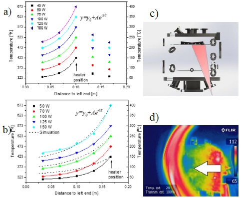
Figure 6 Sample holder temperature measurements with exponential fitting when: a) central and b) right-end heating sections are turned on, respectively; numerical simulations are shown with dashed lines. c) Schematics for the infrared camera line of sight; d) Infrared image of the sample holder heated at right-end at 50 W.
Contact angle as function of temperature
An initial study to test the capabilities involved measuring the contact angle of liquid lithium on tungsten surfaces was held at different temperatures, to compare our measurements with experimental results available [34]. The droplet images obtained from the camera are processed with a Matlab script specifically built to extract the edge from them (see Figure 7 for an example of this process). Once the droplet contour is obtained, mathematical algorithms [35] also programmed in Matlab are used to estimate the contact angle between the lithium droplet and the surface.
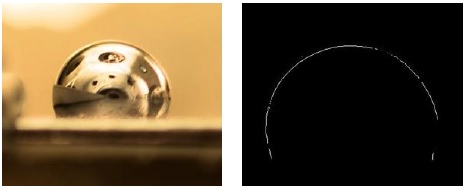
Figure 7 Original still photograph of lithium droplet (left), and the image of droplet resulting from edge extraction algorithm (right).
Results of initial contact angle measurements of liquid lithium droplets on tungsten surfaces with this high-temperature vacuum image goniometer are presented in Table 2, compared with values reported in the literature. There is a large discrepancy between the measurements on this work and the literature; this can be attributed to different wetting properties related to physical (roughness, grain structure) and/or chemical (oxidation, alloying) state of the surface.
Table 2 Contact angle values at different temperatures in the vacuum system including reported contact angles.
|
Temperature (°C) |
Contact Angle (measured) |
Contact Angle [34] |
204 |
73.2 |
130 |
206 |
67.2 |
130 |
244 |
54.2 |
130 |
303 |
54.8 |
130 |
365 |
49.7 |
78 |
The shapes obtained with the Lithium droplets are circular and elliptical depending of surface temperature and/or its roughness (see Figure 8). We worked with liquid lithium on stainless steel AISI 316, and the observations show a good wettability properties at low roughness and high temperature. Further studies regarding the effect of surface physical and chemical states are planned for this facility, in collaboration with other research groups to compare results.
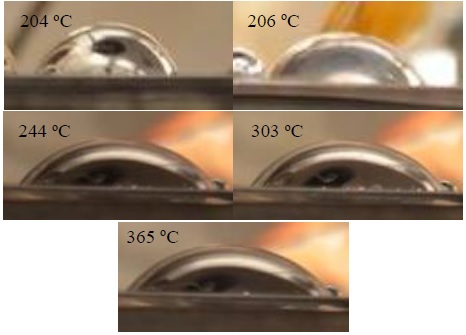
Figure 8 Evolution of the lithium droplet contact angle on the surface of a tungsten sample as surface temperature is increased. Images correspond to temperatures and calculated contact angles are shown in Table 2.
Conclusions
An installation was built to study the interaction of semiconductor and molten metals and their vapor with surfaces of any material subject to a controlled temperature gradient. It has been challenging due to the requirement of high temperatures and enough vacuum to avoid metal surface oxidation. Two goals have been set for this installation: to observe the behavior of condensing vapor in a downward-facing surface held at a temperature above melting point, and the measurement of contact angle of preformed liquid metal droplets in horizontal surfaces.
Regarding the condensation studies, the metal evaporator was calibrated and good agreement was found between actual deposition rate measurements and predictions based on vapor pressure and geometry. In addition, the thermal behavior of the sample holder has been measured and contrasted against 2D finite element thermal simulations. These measurements showed that the thermal gradients achievable in the sample holder are close to those predicted by the simulation, and have been confirmed by both thermocouple measurement and infrared thermal imaging. The first experiments regarding condensation behavior using different kind of substrates (semiconductor crystals, metals and glass) will start shortly in the machine and will be the focus of separate paper contributions.
Additions were made to the vacuum chamber to operate as a high-temperature, high-vacuum goniometer to measure contact angle. A method to generate small liquid metal droplets with no oxidation was successfully implemented, and measurements of contact angle on tungsten as a function of temperature were obtained which show consistency with previously reported measurements. The experimental results demonstrate that it is possible to obtain individual droplets of molten Li, while controlling the substrate surface temperature, in order to study the wetting behavior of the liquid metal. Photographic camera used and post processing algorithms resolve the details of the drop-surface contact to measure the contact angle. In the near future, other experimental parameters to explore include surface type (semiconductors, glass, steel, molybdenum and tantalum), surface roughness and type of liquid metal (ej. Sn/Li eutectic is also of interest in the development of liquid plasma facing components in fusion reactors).

