


Serviços Personalizados
Journal
Artigo
 Inglês (pdf)
 Artigo em XML
 Referências do artigo
 Enviar este artigo por email
Indicadores
-
 Citado por SciELO
 -
 Acessos
Links relacionados
-
 Similares em
SciELO
Similares em
SciELO
Compartilhar

 Permalink
Superficies y vacío
versão impressa ISSN 1665-3521
Superf. vacío vol.27 no.1 Ciudad de México Mar. 2014
Design and simulation of a membranes-based acoustic sensors array for cochlear implant applications
Quiroz G.*, Báez H., Mendoza S., Alemán M., Villa L.
National Polytechnic Institute - Computing Research Center, Mexico D.F., Mexico. *qger@hotmail.com
Recibido: 28 de noviembre de 2013;
Aceptado: 28 de febrero de 2014.
Abstract
In this work we present the design and simulation of an acoustic sensors array for detecting specific frequencies in a range, and allowing their identification from a complex audio signal in order to develop an application for cochlear implants. The sensitivity is obtained when a membrane resonates when stimulated by an audio signal which behaves as a mechanical wave. The structure of each sensor is designed with the concept of MEMS capacitive microphones, formed by a flexible membrane between two rigid backplates. The variation of the distance between the membrane and backplates generates a capacitance change that can pass to an electronic readout circuit. The structure has been designed as a mass-spring system where a set of springs, with the same elastic properties, holds the flexible membrane.
Keywords: MEMS; Microphone; Capacitive; Cochlear; Implant; Simulation.
1. Introduction
The problem of hearing loss is treated with different alternatives, from hearing aids to cochlear implants; the second ones are devices that realize a digital processing of audio signals to separate some frequencies and then, to send electric pulses to an array of electrodes inside the cochlea, stimulating electrically to the cells responsible of detecting the vibrations produced by any acoustic signal [1,2]. In the human ear, the cochlea is the responsible for separating the frequencies that constitute a complex audio signal.
An alternative to the traditional directional microphones used in cochlear implants is to develop a device that can detect an audio signal and at the same time separate and identify the center frequencies. For this, in this work MEMS microphones are used, which began to be used in different applications due to their low cost and integration in signal analysis. They are very practical by not being affected by external acceleration. Capacitive microphones can detect a wide range of acoustic information, its operating principle is already well studied and they are used in different applications.
MEMS microphones are designed and fabricated using different structures, each one with advantages and disadvantages. One of these structures uses a polysilicon membrane which moves when a sound pressure hits on its surface; some structures additionally implement acoustic perforations on the fixed reference membrane obtaining, in the same way, a variable capacitance.
2. Device description and design
2.1. Device design
In this work the SUMMiT V platform design is used. This tool allows to define 4 mechanical layers of polysilicon (MMPoly1-4) fabricated above a thin highly doped polysilicon layer (MMPoly0) and a sacrificial oxide (SacOx) sandwiched between each polysilicon level. The thin sacrificial films define the amount of mechanical play the polysilicon layers can have. An optional patterned metal layer can be applied to the upper polysilicon layer for electrical connections. There is a process to planarize each oxide for the next polysilicon layer, this feature is important for the proper behavior of the microphone.
2.2. Structure description
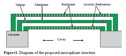
The proposed structure is formed by a movable membrane and two rigid backplates [3,4], forming a structure with two parallel plate capacitors [5]. The movable membrane responds and changes its position when the acoustic pressure hit its surface, producing a capacitance variation between the backplates and the membrane, which in turns produces a current flow proportional to the distance variation between the membrane and the backplates. Before removing the sacrificial oxides, a cavity must be opened from the backside of silicon substrate, below the capacitor structure, here the sacrificial oxides give mechanical support to the polysilicon structures. After the cavity is formed, the sacrificial oxides are removed using a HF solution.
The movable membrane is held by a set of springs, which designs allow modifying the device sensitivity. Acoustic perforations made in the upper and lower backplates allow the passage of the acoustic signal and homogenize it over the whole membrane surface, also they allow an air-exchange with the ambient to prevent abrupt pressure changes. In figure 1 is shown the structure of the presented microphone.
It is proposed an array of 14 microphones, each of them responding to a specific frequency from a defined range. This is precisely the new characteristic shown in this work, the possibility to define the resonance frequencies of each membrane. The analyzed frequency range was selected from 512 Hz to 4.2 kHz, which is where the intelligent information of the voice is contained. Within this selected range, a second division was made, defining three intervals: low (from 537 Hz to 830 Hz), medium (from 1002 Hz to 1642 Hz) and high (from 1905 Hz to 4231 Hz) frequencies.
Taking into account all this considerations, it is also possible to implement the microphones array like a mechanical filters array. It is proposed an application as a complement of the processing done by a DSP in a cochlear implant. Due to the double application of the array, as an acoustic sensor and as a mechanical filter, it is expected a reduction not only in the complexity of the DSP signal processing but also a reduction of the final size of the device. The use of individual membranes to detect specific frequencies results in a greater selectivity of the sampled frequencies.
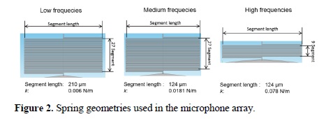
Three different geometries of springs were designed, considering the three frequency intervals, each one with own elastic properties; one reason to different designs is to avoid the overlapping between them. An important consideration is that the minimum number of spring used in each membrane is four. In figure 2 the three different geometries for the springs are shown, indicating the dimensions for each case. The geometries for low and medium frequencies use the same number of segments but different length. On the other hand, geometries for medium and high frequencies use the same length but different number of segments. For each case, there is a value for the elastic constant (k). For each frequency interval, just the defined spring is used and no mixture of them is allowed.
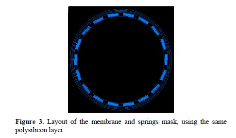
The membrane and the springs are fabricated with the same polysilicon layer, 2.25 µm thick MMPoly3 of the SUMMiT V process. The widths of all segments were established in 1 µm, which is the minimum value defined by the design rules. The figure 3 shows the layout mask used to define the membrane and springs. The 14 membranes of the array have the same diameter, as shown in diagram of figure 4, and depending of the number of springs and its geometrical characteristics the specific frequency at which each microphone responds when stimulated by a complex audio signal can be modified.
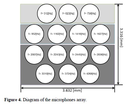
It can be seen that the array has a proper size to be implemented, with complementary electronics, in the audio detection stage of a cochlear implant.
The frequencies at which each device respond have been defined through the center frequencies used in Mel filters, which are commonly used in the field of digital signal processing allowing to calculate the coefficients that represent the human speech based in methods of human auditory perception, this way it is also possible the pattern recognition in audio signals [6].
The number of acoustic perforations in each plate is in function of its size. Acoustic perforations have been reported between 5 to 10 µm of diameter [5,9], being their most relevant functions to allow the incident acoustic pressure to pass through the plates and hit homogeneously the membrane and to promote the total removal of the sacrificial oxide during the wet etching to release the polysilicon structures.
In this work the diameter of the acoustic perforations were defined in 6 µm, taking into account the design rule of SUMMiT V platform [7] that indicates the spacing between the perforation centers must be at least 38 m for the proper fabrication process and for the correct removal of the sacrificial oxides.
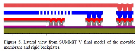
Following the design rules of the Sandia Labs SUMMiT V design platform [7], the thicknesses of each layer that form the membrane and backplates are guaranteed, ensuring then the final dimensions of the structures. The corresponding layers are: MMPoly3 (2.25 µm) for the movable membrane and MMPoly1+MMPoly2 (1 µm + 1.5 µm) and MMPoly4 (2.25 µm) for the rigid backplates. Another advantage of this platform is the flattened layers obtained after processing SacOx3 and SacOx4 (2 µm each). The final modeled structure is shown in figure 5.
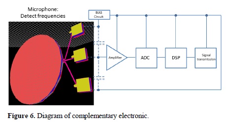
The figure 6 shows a diagram of a complementary electronics proposed to read the behavior of the membrane.
3. Mathematical model
The model that allow to know the membrane oscillation mode was determined using the Lagrangian function, with this the different normal oscillating modes of the system were observed [8]. In this first approach, the mathematical model does not consider all the parameters that have influence on the devices behavior.
The corresponding set of springs are equally spaced, so each spring load an equal part of the membrane. The elastic constant of the system consider the sum of the elastic constants of the springs, due to they are in parallel.
The differential motion equation has a solution given by,

so the first and second derivatives are known, which are necessary to rewrite the equation. Simplifying the expression dividing by cos (ωt) and making the variable change,
an eigenvalues analysis is obtained, now is possible to know the response of the mass-spring system as a function of the movable membrane mass and the springs elastic constant (ks), given by

The next step is to match the frequencies of the human voice bandwidth, relating the equation of simple harmonic movement with the response of the system, which is a function of the number of springs (N) and the elastic constant of a single spring.
3.1. Spring model
The design of the springs is a critical part of the complete design, because the expected way the membrane behaves due to an acoustic pressure stimulus is a function of the value of ks of each spring. On the other hand, it should be taken into account the maximum displacement in the spring, because if deforms more than the air gap between the membranes, they may hit and be damaged. Therefore it is important to take into account the spring elastic properties.
To calculate the geometry of the springs, as mentioned above, it is considered that they are fabricated using MMPoly3 layer, the diameter of the membrane is 700 µm, polysilicon density is 2.3 g/cm3, obtaining a membrane mass of 1.992e10-9 kg. The maximum displacement of the membrane cannot be bigger than 1.5 µm, because of the width of sacrificial oxides (SacOx3 and SacOx4), and the considered pressure on the membrane is 0.02 Pa which is the equivalent of a normal conversation (60dB).
Knowing the membrane area and the pressure on it, the resulting exerted force is F=7.697e10-9 N. From Hooke's Law it is possible to calculate the minimum value for the elastic constant of the springs, because this expression relates the deformation and the spring elastic constant in an inversely proportional way, thereby obtaining the ks minimum, which is kmin = 0.006 kg/s2.
Once knowing the values of ks that will be used for the membranes, it is possible to calculate the number of springs for each system. Table 1 shows the values of frequencies, their corresponding values of spring elastic constant and number of springs used to hold each movable membrane, values are shown in the three defined frequency intervals.
Values on Table 1 show a proper number of springs and also they are distributed over the whole circumference of the movable membrane without overlapping or any interference among them.
4. Simulations
In this work the simulations were made using COMSOL Multiphysics. This is a computational tool for multiphysics analyzes to study and to predict the behavior of one or several structures under specific conditions. One of its versatilities is the possibility of coupling different physical phenomena in the same study. It is possible to obtain analyzes very close to the actual conditions to those the final device will undergo.
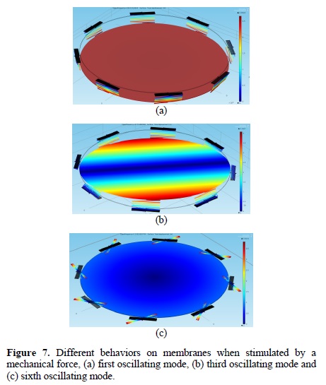
The proper behavior of the membranes was verified by simulations, taking into account different aspects that influence the behavior and actual operating conditions. In this way, it was found that the proposed mathematical model is very close to the expected real behavior of the system. The results show that the theoretically calculated normal modes match the Eigenfrequencies values obtained from multiphysics simulations in the whole proposed frequency range. The behavior of the movable membrane obtained from simulations is shown in the figure 7, where three different normal oscillating modes which behavior is the same in all membranes independent of the geometry of the springs used are illustrated.
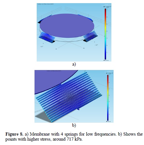
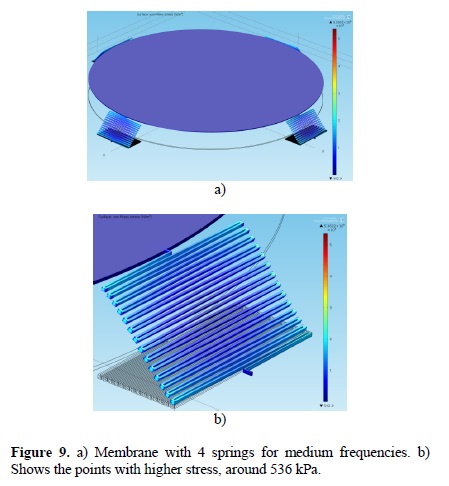
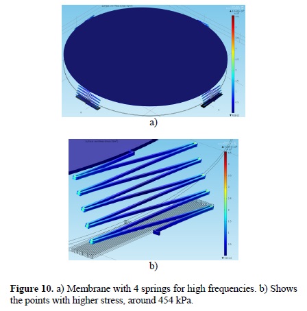
The value of the polysilicon Young's modulus is 160 GPa. Figures 8, to 10 show the stress in the springs. It has been reported that polysilicon rupture stress is between 1 to 4 GPa depending on the accumulated stress in the structure [10,11]. In this work, the maximum stress obtained in springs is 717 kPa, as shown in figure 8, which is below the critical point for causing a rupture.
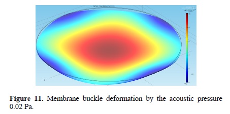
The deformation of the membrane originated by a pressure of 0.02 Pa was studied, and it was observed that the deformation in the membrane is negligible (there is a negligible buckle deformation) compared with the total displacement of the membrane in reference to the rigid plates. The membrane total displacement is about 10-6 to 10-7 m and its buckle deformation is on the order of 10-10 m.
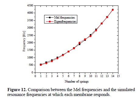
On the other hand, a comparison between the Mel frequencies and the simulated resonance frequencies at which each membrane responds as a function of the number of springs is shown in figure 12. In this comparison it can be observed a perfect match between values in the whole proposed frequency range.
5. Conclusions and discussion
The design and simulation of an acoustic membrane-based sensors array for detecting specific frequencies in a range was presented. Design is based on a MEMS capacitive microphone structure, using a movable membrane between two rigid backplates. Simulations of the membranes behavior when an audio signal hits its surface were done, obtaining values for resonance frequencies which are very close to the Mel frequencies values in the proposed range. Multiphysics simulations were done in order to verify the mechanical properties of the material and oscillating modes in the structure. Simulation results demonstrate that the behavior of the structure is very close to the expected real behavior of the system.
From the equation that shows the behavior of the membrane anchored by springs, and knowing the mass of the membrane, it was possible to define the elastic properties and the number of springs necessary for each membrane, in order to detect specific frequencies from an audio signal. Different spring geometries were proposed to evaluate their elastic properties and to find the closest values to the theoretical analysis. The analysis showed, in some cases, the use of just one spring and, in other cases, a large amount that would result in overlapping; neither of these two results is useful for the correct operation of the device. The solutions was to use three different springs geometries, each of them was used in a different frequency range (low, medium, high) to avoid having inconsistent amounts of spring anchoring the membrane. The final three geometries have elastic constants (k) very close to those proposed in theoretical analysis, thus the number of springs required is determined for each case.
After performing the simulations using, it was observed that the number of springs used in each membrane is appropriate, so that the Eigenfrequencies study showed values corresponding to frequencies to be detected. Hence, the simulations prove satisfactorily that each system has the expected behavior when compared with the behavior described in the theoretical analysis. Each microphone has a custom design with very specific characteristics.
Therefore, the specific frequency identification from a complex audio signal can be used to develop a device widely used in cochlear implants. The final prototype of the device is being fabricated by The Sandia National Laboratories. In future work, the complementary electronics will be designed and implemented in order to measure the device response and compare it with theoretical results.
References
[1] C. Luo, J. H. McClellan, and P. T. Bhatti, Introductory Signal Processing Labs Based on Filterbank Applications, in Proc. of the IEEE Digital Signal Processing Workshop and IEEE Signal Processing Education Workshop (DSP/SPE), pp. 90-94 (2011). [ Links ]
[2] P. Loizou, IEEE Signal Processing Magazine, 15, 101 (1998). [ Links ]
[3] T. Kasai, S. Sato, S. Conti, I. Padovani, F. David, and Y. Uchida, Novel Concept for a MEMS Microphone with Dual Channels for an Ultrawide Dynamic Range, in Proc. of the IEEE 24th International Conference on Micro Electro Mechanical Systems, pp. 605-608 (2011). [ Links ]
[4] C. Chan, W. Lai, and M. Wu, IEEE Sensors Journal, 11, 2365 (2011). [ Links ]
[5] J. Liu, D. Martin, T. Nishida, L. N. Cattafesta, M. Sheplak, and B. P. Mann, Journal of Microelectromechanical Syst., 17, 698 (2008). [ Links ]
[6] T. Ganchev, N. Fakotakis, and G. Kokkinakis, Comparative Evaluation of Various MFCC Implementations on the Speaker Verification Task, (SPECOM-2005). [ Links ]
[7] SUMMiT V Five Level Surface Micromachining Technology Design Manual, version 3.2, October 25, 2012. Sandia National Laboratories, MEMS Technologies Department, Microelectronics Development Laboratory, 2012. [ Links ]
[8] Dare A. Wells, Schaum's Theory and Problems of Lagrangian Dynamics. (Schaum-Publishing Co., 1967). [ Links ]
[9] D. T. Martin, J. Liu, K. Kadirvel, R. M. Fox, M. Sheplak, and T. Nishida, Journal of Microelectromechanical Systems, 16, 1289, (2007). [ Links ]
[10] J. Bagdahn, W. N. Sharpe, and O. Jadaan, Journal of Microelectromechanical Systems, 12, 302 (2003). [ Links ]
[11] W. N. Sharpe, R. Vaidyanathan, and R. L. Edwards, Measurements of Young's Modulus, Poisson's Ratio, and Tensile Strength of Polysilicon, in Proc. of the IEEE 10th Annual International Workshop on Micro Electro Mechanical Systems, pp. 424-429 (1997). [ Links ]

