


Servicios Personalizados
Revista
Articulo
 Inglés (pdf)
 Artículo en XML
 Referencias del artículo
 Enviar artículo por email
Indicadores
-
 Citado por SciELO
 -
 Accesos
Links relacionados
-
 Similares en
SciELO
Similares en
SciELO
Compartir

 Permalink
Superficies y vacío
versión impresa ISSN 1665-3521
Superf. vacío vol.26 no.4 Ciudad de México dic. 2013
Tribological evaluation of plasma nitride H13 steel
Solis Romero J.1*, Medina Flores A.1, Roblero Aguilar O.1, Oseguera Peña J.2
1 SEP-DGEST-Instituto Tecnológico de Tlalnepantla Av. Tecnologico s/n, Col. la Comunidad, Tlalnepantla de Baz, Edo Mexico, 54070. Mexico. *josesolis@infinitum.com.mx
2 Instituto Tecnológico y de Superiores de Monterrey campus Estado de México Carretera a Lago de Guadalupe km 3.5, Atizapán Edo. Méx., 52926 México.
Recibido: 29 de septiembre de 2013.
Aceptado: 2 de diciembre de 2013.
Abstract
The influence of nitriding time and applied load in the friction-wear behaviour of an H13 steel has been studied. Weakly ionised plasma unit and a postdischarge plasma reactor were used for nitriding the H13 die steel with variations of nitriding time from 5h to 9h (at 500 °C). Optical microscopy and microhardness deep profiles of the nitrided layer were obtained for each nitriding time. Standard pin-on-disc wear test were conducted at ambient temperature (18-23 °C) and dry sliding. It was observed that the higher the nitriding time, the lower the friction coefficient variations and wear rate varied as a function of the applied load. Plastic deformation and abrasion wear resulted to be the main wear mechanism for short sliding distances, while for long sliding distances plastic deformation dominated the wear mechanism and to some extent oxidative wear. The compound layer (white layer) was central for wear and load capacity.
Keywords: Plasma nitriding; H13 steel; Wear; Pin-on-disc; Tribology.
1. Introduction
The aim of achieving materials with better lifetime has given impetus to the emergence of new technologies and consequently to developments in the understanding of, among others, tribological properties. These challenges have attracted a considerable number of scientists and engineers. Plasma nitriding has been a successfully surface hardening process employed to enhance the fatigue strength, wear and corrosion resistance of bulk materials [1]. This thermochemical treatment involves diffusional addition of nitrogen into the surface of metallic materials. Two different structures are formed from surface to core, namely, a compound layer (white layer) and a diffusion layer. In the former layer generates as epsilon phase (e-Fe2N, ε-Fe3N), gamma phase (γ'-Fe4N), or mixed phase (ε+ γ') whereas in the diffusion zone, N atoms are dissolved interstitially in excess in the ferrite lattice to give rise to formation of nitride precipitates (CrN) [2, 3]. These compound layers are, generally, hard and brittle but the thin monophase y' produced by plasma nitriding is extremely ductile and wear resistant according to the e phase. Thus, wear characteristics of the compound layer depend on several factors, namely, compound layer composition (ε/ γ'), its thickness, loading type, etc. [4, 5]. From the different nitriding techniques available such as liquid nitriding, gas nitriding and plasma-assisted nitriding; nitriding in the post-discharge flow of microwave generated plasma has proven to reach higher values of nitrogen potential than those achieved in other plasma nitriding treatment [6]. Accordingly, the nitrogen surface concentration can quickly reach the value corresponding to the equilibrium between the atmosphere and the y' or e nitride phases. The process has been successfully applied on H13 steel to improve surface mechanical properties [3].
In particular, although higher hardness levels in shorter nitriding times were obtained respect to other plasma methods, tribological properties were not assessed. It entails the characterisation of tribological properties in terms of friction and wear behaviour.
Wear of extrusion dies has an important technological and economic significance due to cost in order to prevent die failure from thermal cracking, erosive wear, soldering and corrosion or a combination of these processes. H13 die steel is characterised by its high hardenability and toughness, but a relatively low wear resistance. The savings that result from increasing the lifetime of the dies by the enhancements of its tribological properties have motivated researchers to optimise surface treatments suitable to these materials. Therefore, the purpose of the present work is to investigate the influence of a plasma nitriding time on the friction and wear behaviour of H13 steel. To accomplish this undertaken, evaluation of dry friction and wear mechanism at ambient temperature as a function of nitriding time and sliding distance during pin-on-disc wear tests was carried out.
2. Materials and Experimental Methods
Nitriding of an H13 die steel was performed in a dual plasma reactor which incorporates a weakly ionised plasma unit that provides continuous cleaning of the sample by sputtering plus heating by ion bombarding and a post-discharge plasma reactor that supplies a highly reactive atmosphere. The apparatus used for the nitriding treatment is shown in Fig.1.

The substrate of the samples in this study was H13 die steel with the following nominal chemical composition (wt. %):0.32-0.45% C, 0.20-0.50% Mn, 0.80-1.20% Si, 4.755.50% Cr, 1.10-1.75% Mo, and 0.8-1.20% V. The samples with size of 3cm long, 2cm wide, and 2.5 cm thick were first quenched (austenizing at 1020 °C for 2 h, cooling in forced air to room temperature) and two tempering treatments (at 540 °C for 2 h each, followed by forced convection cooling). The hardness of the resulting microstructure was 560 HV0.1. The decarburized layer that formed at the surface during heat treatment was removed by grinding. The surface of the sample exposed to the nitriding atmosphere was polished with silicon carbide emery papers and diamond paste to mirror finish (Ra = 0.1±0.02 µm). Nitriding temperature was 500 °C and the nitriding times were 5 h and 9 h, all selected by virtue of minimum and maximum hardness response, respectively as well as the large variation of these as a function of time, as put forward in previous work [3]. Specimens were obtained for cross-sectional analysis by optical microscope. The samples surface was examined by means of X-ray diffraction (XRD), both with and without the surface compound layer (white layer). The compound layer was carefully removed by controlled polishing with 6 urn diamond paste. For microscopic observation, the microstructures of the case depth and substrates were revealed on polished and etched cross sections in a 2% nital solution.
The pin-slid-on-disc (see Fig.2) wear experiments against AISI 52100 (100Cr6) steel ball with 6mm in diameter, 800±40 HV01 hardness and Ra of 0.013 urn were performed in ambient environment with temperature 20-25 °C, humidity 44±5% and no lubricant. Friction force is determined by direct measurement (with a piezoelectric element) of the tangential force applied on the flexible arm. The friction coefficient is given by the ratio between the friction force and the normal force (applied load). The vertically applied loads at the top of the specimens were selected to 2, 5, 7 and 10N; the sliding speed maintained 0.02m s-1, and the diameter of the wear track circle slightly varied from 12 to 14mm. The experimental procedure was undertaken according to ASTM G99-95a [7]. Wear losses were determined by wear track measurements and by weight-loss method. Volume loss from flat disc was worked out, assuming no significant pin wear, by means of [7]:
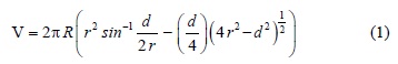
where R denotes the wear track radius; r represents pin sphere radius (3 mm); d the track width.

Analogously, volume loss from a spherical ended pin was determined by:

where  represents pin end radius (3mm) and d is the wear scar diameter.
Disc wear tracks and pin wear scars were measured by image analysis with an Olimpus metallographic light microscope connected to an Image-Pro image analyser. Track widths are the mean values after 12 measurements performed along the pin trails. Mass loss was measured using an electronic balance with precision of 0.1 mg.
For determining the wear rate, typically denoted by K, the Holm/Archard's relationship was used [8]:

where V (mm3) is the worn volume, w (N) is the normal force applied and s (m) is the total sliding distance. For this research, however, the wear volume divided with the sliding distance was defined as the wear rate because the normal force applied was the variable parameter. To identify the wear mechanisms, worn surfaces were observed through the scanning electron microscopy plus energy dispersive X-ray spectroscopy (SEM + EDS) both on top surfaces and also on polished and etched cross sections. The HV0.05 microhardness profiles of the nitrided layers were obtained in the cross section by means of a Shimadzu MMV-2 instrument.
3. Results and Discussions
3.1. Surface hardness and microstructure
The hardness evolution for a choice of nitriding times at 500 °C is depicted in Fig.3. There can be seen a significant increase in both a compound layer and a diffusion zone over the matrix hardness. Maximum hardness of the compound layer reached values on the order of 1100 HV0.1. It is also observed that the maximum hardness of the nitrided layer (1350 HV0.1) was located near to 20 µm below the surface. After these subsurface peaks, hardness exhibited a monotonic decrease in depth, although hardness for 9 h nitriding showed a flatter profile from which the hardness values were as high as 1200 HV0.1 at 180 µm depth. Castro et al. [9] achieved hardness values on the order of 1100 HV0.05 for H13 nitrided in a salt bath activated with sulphur (sursulf nitriding) after 9 h treatment and with a diffusion layer of 110-140 µm depth. For longer nitriding times the surface hardness converged into 1100 HV0.05. There was only a case for the 15 h (190-240 µm) in which a hardness of 1150 HV0.05 was reached. It is interesting to note that whereas for the Castro et al. research no compound layer grew before a nitriding time of 7 h at 580 °C, in this work, such layer growth was observed from nitriding times of 5 h upwards and at 500°C. Their previous heat treatment condition to the nitriding treatment was quite similar to heat treatment condition carried out in the present study, which demonstrates that the present method offers some improvement over other nitriding methods, especially in the attainment of flatter hardness profiles which do not favour the development of residual stresses in the hardened layer.

The microstructure for the 9 h nitriding, shown in Fig. 4a consists of an internal nucleus of tempered martensite and a nitrided layer in the external surface. The nitrided layer consists of a nitrogen diffusion region with fine elongated nitride plates precipitated and a shallow compound layer on the outside part. In the X-Ray diffraction pattern of Fig. 4b it is indicated that the compound layer consisted mainly of e-nitride together with rich γ'-nitride and a mixed phase (ε+γ') on the diffusion zone of the nitrided surface. Below the compound layer, the presence of CrN with a small amount of ferrite appears in the diffractogram of Fig. 4c. Generally speaking, at short nitriding times (5 h), there is not enough of the CrN phase to result in a high value of hardness, however, at intermediate times (8-9 h); there is an optimum amount, size, and distribution of CrN, which after longer times (> 10 h), it coarsens and as a result, a drop of hardness occurs (see Fig. 3).

3.2. Tribological properties
The measurements of the coefficient of friction for plasma nitrided and non-nitrided H13 steel samples as a function of sliding distance/cycles at 2N and 5N sliding loads and 12 mm diameter of the wear track circle are shown in Fig. 5a-b. The friction coefficient variations for a load of 7N and 14 mm diameter of the wear track circle are given in Fig. 5c. The coefficient of friction for the non-nitrided H13 steel for all different loads changed as a function of the distance slid, particularly in the early stages of sliding. It usually exhibited a low initial value (in the range of 0.1-0.2) but rapidly increases until reaching a steady state value. The substantial augment of the frictional force is in turn, a result of the rapid increase in the number of wear fragments entrapped between the sliding surfaces, where some of them, mainly from the disc material, plough such surfaces as can be seen in Fig. 6a. Worn surface consist of ploughed grooves and plastically deformed regions in the sliding direction. These fragments are generated by subsurface deformation, crack nucleation and crack propagation [10]. This can be confirmed by taking a closer look as shown in Fig. 6b. The frictional force is also affected by the escalation in adhesion due to the increase in clean interfacial area as observed by the large variations in the friction coefficient from 0.2 to 0.8 all along the steady state. After a maximum value was reached, the friction coefficient slightly drops to an average value of 0.6 (see Fig. 5). The drop in the friction coefficient is associated with mutual polishing of the mating surfaces and such behaviour results principally when the hardness of the pin is greater than that of the moving disc [10]. Comparable friction coefficient values, and in general, analogous tribological behaviour from pin-on-disc tests with a steel ball dry sliding on a steel disc has been previously reported by H. Czichos et al.[11].


In the case of longer sliding distance, the friction coefficient does not exhibit any substantial change, i.e. an average value of 0.6 is sustained as well as high friction coefficient variations. Nevertheless, while part of the removed material remains in the contact between pin and disc generating the thin abrasion grooves as observed in Fig. 6, some transfer of material from steel counterbody to H13 steel non-nitrided was exhibited in the form of located heaps on the wear track of the H13 steel. Wear rate of steel counterbody for sliding distance of 30 m was 3.69 (mm3 N-1 m-1 x 10⁻⁵), whereas for sliding distance of 100 m was 8.26 (mm3 N-1 m-1 x 10⁻⁵). This substantial ball wear increase suggest that large debris particles might have formed causing thick wear tracks with the evident surface penetration. Majority of the removed particles accumulated were pushed through the worn surface of the wear track and during testing deposited on the side of the wear track in the sliding direction. Therefore, large friction coefficient variations are attributed to hard particles ploughing the sliding pair and to some extent the adhesion between smashed substances coming from the pin.
The nitrided steel, in turn, exhibited a similar friction coefficient pattern for all loads and nitriding times, characterised by the initial running-in period followed by a gradual increase until reaching a gradual steady state. A low initial value of 0.1 was recorded but in this case, there was a gradual ramp up until reaching a steady state value whose range oscillated from 0.4 - 0.5. The initial running-in corresponds to the contact of the disc highest asperities and the ball surface. The gradual increase of the friction coefficient shown in Fig. 5(a-c) can be associated to the real contact between the thin compound layer and the steel ball surface as this leads to an increase of the applied stress on the wear surface and, thus, to the plastic deformation of material. This friction coefficient behaviour also suggests some similitude in hardness both the pin and the disc. On the other hand, for 30 m sliding distances, the compound layer begins to wear out, as seen in Fig. 7. From this figure, the compound layer is being both plastically deformed and partly removed from the wear track. Furthermore, it is observed some degree of compound layer detachment, which can be attributed either the higher contact pressure than the pressure capacity of such layer or the inherent brittleness of such compound layer. In this respect, it is well known the fact that a mixed phase (γ' + ε), typically observed in gas nitriding, can be prone to spalling since it is brittle and breaks down during the early stage of wear tests [12-13]. In addition, the brittleness of the compound layer is influenced by the ε/ γ' phase ratio [5].

A detailed examination of the mildly worn surface of H13 steel nitrided for 9 h is shown in Fig. 8. The higher magnification in Fig. 8 depicts the plastically deformed layer and also it can be seen part of the compound layer underneath this smashed layer. This degraded surface consists of shallow ploughed formations, where a new compacted surface in the valleys can be distinguished as a result of the plastically deformed material and the agglomerated wear debris. The wear rate of steel counterbody at this stage was 1.223 (mm3 N-1 m-1 x 10⁻⁵). It thus appears that small debris particles were formed with faint surface penetration. These observations are consistent with friction coefficient variations of H13 steel nitrided, and in particular for 9 h nitriding and sliding distance of 30 m, since it exhibited the smallest variations as seen in Fig. 5 (a-c). In general, it is observed that plasma nitriding and specifically the compound layer has effect on the friction coefficient variations: the higher the nitriding time, the lower the friction coefficient variations. As expected, dry sliding resulted in larger friction coefficient variations for the non-nitrided H13 steels.

The aforementioned observations are also consistent with the wear behaviour of tested steels, as graphically presented in Fig. 9. From this figure, independently of the non-nitrided alloy results, two major observations are underlined and hence, to be analysed. The first one is associated with the applied load, i.e., it is observed that for a given nitrided time, the wear rate increases as a function of the applied load. This can be ascribed to the mildly removal of the compound layer with the progression of the test. The increment of the normal applied load leads to a rise of the applied shear stress on the wear compound layer resulting in the eventual removal of metal slivers. The second one is related to the nitriding time, i.e., a correlation between surface hardness-appearance-thickness and wear resistance of the compound layer. The H13 steel nitrided during 9 h exhibited the lowest wear rate values clearly manifested at all tested loads, whereas for the H13 steel nitrided during 5 h, higher worn volumes were observed. The local pressures at the points of asperity contacts forge metallic junctions between surfaces. At a given load, friction coefficient (µ) strongly depends on the real contact area which it can be associated with its appearance and surface hardness corresponding to the deformation resistance of the contact area, according to the well known relationship  , where A would be the real contacta area, t the shear strength of the junction, F the applied normal load and H the mean pressure on an asperity or simply the local hardness of the material. The hardness of the compound layer for 9h and 5 h nitrided steels was recorded to be 1100 ±100 HV01 and 850 ±100 HV01 respectively. Shallow wear tracks as well as relatively large wear scars on the steel counterbody (800±40 HV0.1) were also observed. Therefore, it is clear that the harder surface often corresponds to the higher deformation resistance to prevent the particles, adhered to the softer surface, from pressing into it and protect it from being worn out. Thickness of the compound layer, in turn, influences the wear rate behaviour, i.e. thicker compound layer and nitride layer may provide higher load capacity and deformation resistance, which again, prevents the compound layer from being worn out. Wear rate discrepancies in Fig. 9 may also be attributed to shuffling off the compound layer by the trackside. As the test progresses the ball scar grows up due to the large-scale wear and consequently it cuts off the trackside, widening the disc wear track.

In order to reach a clearer insight into the behaviour of friction coefficient for nitrided H13 steel alloys sliding against steel, friction variations of H13 nitrided during 9 h and H13 non-nitrided, tested at 2 N applied load for longer sliding distances were attained as shown in Fig. 10. It was observed that in H13 steel nitrided, large friction coefficient variations took place up to sliding distances above 700 m whereas for the non-nitrided steel, comparable variations were observed at sliding distances of 25 m onwards. These findings reveal that the growth of a compound layer (white layer) on top of nitrided layer (nitrogen diffusion zone), for the actual nitriding process, hinders the generation of hard particles or fragments due to the sliding and therefore, slows down ploughing on the sliding disc. This particular behaviour may be interpreted in terms of the ε/ γ' phase ratio, i.e. the presence of copiously γ'-nitride (Fig. 3b) in the compound layer increases ductility and wear resistant according to e phase [14].

For longer sliding distance and larger applied load, the friction behaviour exhibited the expected features of large plastic deformation followed by a substantial material transfer. Material transfer was mainly observed from the counter-body deposited in the form of patches and to some extent of heaps on the compound layer surface. Those patches and heaps appear as add-on substances both for 2 N and 7 N applied load as shown in Fig. 11. Energy dispersive X-ray analysis (EDS) of the adds-on substances obtained in the worn surface of H13 nitrided for 9h and at 2N described a low percentage of chromium and high percentage of carbon and iron, in addition to silicon and oxygen but no nitrogen. It indicated that the transferred material corresponded to the pin.

On the other hand, the friction behaviour for such longer distances can be appreciated in Fig. 12. A comparison between 2N load and 7N clearly shows the shear and transfer effects. Accordingly, highest friction variations are observed above 700m for 9h steel nitrided subjected to 2N applied load. In the case of the 9h steel nitrided with a 7N applied load, massive friction variations come out early around 70m, however, interestingly in this later case, the tribometer suddenly stopped itself by 95 m sliding distance. Evidently, the machine did not manage to carry on due to the frictional forces arisen as a consequence of the larger load. In this respect, under large enough loads the local pressures at the asperity contacts junctions are sheared and therefore, both the real contact area and the nominal area grow because of plastic indentation, mass flow and metallic transfer. These latter effects have been identified as the basis of catastrophic junction growth mainly caused by shear. Following that large-scale mass flow and metallic transfer, the real contact area is.

This condition was identified and modelled as the wear mechanism of seizure [15]. Thus, the 9h steel nitrided seized at about 95 m under 7N applied load.
4. Conclusions
In the present work, the AISI H13 hot work steel was ion nitrided with a dual plasma reactor and surface analysed to measure the frictional and wear characteristics. Pin-on-disc wear tests have been conducted at ambient temperature and dry sliding in both short and long sliding distances. The following conclusions can be derived from the results. Nitriding of H13 die steel by using a dual plasma reactor offers a substantial advantage over conventional gas nitriding as it provides higher hardness levels in shorter nitriding times.
At short nitriding times (5 h), there is not enough of the CrN phase to result in a high value of hardness. At intermediate times (8-9 h) there is an optimum amount, size, and distribution of CrN which provides the highest hardness values as well as the best hardness profiles. For longer times (> 10 h), CrN coarsens and a reduction of hardness occurs.
The friction coefficient of the nitrided steel under this plasma method increase in the early stage of the wear tests up to a steady state value of 0.4-0.5, regardless the applied load. A steady state friction coefficient of 0.6 for the non-nitrided steel was obtained, also regardless the applied load. At early stages, asperity deformation was identified as the friction-generating mechanism for nitrided steel. For the subsequent stages ploughing showed to be the friction mechanism. Adhesion was significantly increased for long distances, particularly due to the material transfer. The compound layer has effect on the friction coefficient variations: the higher the nitriding time, the lower the friction coefficient variations.
Wear behaviour on the short sliding distance test was characterised by the influence of two wear mechanisms: plastic deformation and abrasive wear. For long sliding distances the wear mechanism controlling the wear rate was the plastic deformation and to some extent, the oxidative wear. Wear rates of 9h nitrided steel were lowest for all applied loads.
For long sliding distances and large applied loads, the contact area of the counter-body eventually equals the worn surface area and, as a result, the condition of seizure ensues. Due to the latter, the frictional force becomes so high that the test is stopped since the device has not got the power to keep the specimen in rotation.The compound layer enriched with gamma nitride and epsilon nitride generated by the nitriding of H13 die steel in a dual plasma reactor hinders the generation of hard particles or fragments due to the sliding and therefore, slows down ploughing on the sliding disc. Therefore, this layer resulted to be beneficial in terms of wear and load capacity.
Acknowledgments
The authors gratefully acknowledge SEP-SES-DGEST-ITTLA and ITESM-CEM, for the support of this research project.
[1]. Mehmet Baki Karamiş, Kemal Yildizli, Gamze Çarkit Aydin. Tribology International, 51, 18 (2012). [ Links ]
[2]. Shi Li and Rafael R. Manory. Journal of Materials Science, 34,1045 (1999). [ Links ]
[3]. O. Salas, J. Oseguera, N. García and U. Figueroa. ASM International, 10, 649 (2001). [ Links ]
[4]. M. Tercelj, A. Smolej, P. Fajfar and R. Turk. Tribology International, 40, 374 (2007). [ Links ]
[5]. P. Psyllaki, G.Kefalonikas, G. Pantazopoulos, et al.. Microstructure and tribological behaviour of liquid nitrocarburised tool steels. Surface & Coatings Technology, 162, 67 (2002). [ Links ]
[6]. J. Oseguera, O. Salas, U. Figueroa and M. Palacios. Surface & Coatings Technology, 94, 587 (1997). [ Links ]
[7]. Standard Test Method for Wear Testing with a Pin-on-Disk Apparatus (ASTM G99 95a 2000). [ Links ]
[8]. Kenneth Holmberg and Allan Matthews. Elsevier Science B.V. ISBN: 0 444 88870 5 (Amsterdam, The Netherlands 1994). [ Links ]
[9]. G. Castro, A. Fernández-Vicente and J. Cid. Wear, 263, 1375 (2007). [ Links ]
[10]. Nam P. Suh and H.C. Sin. The genesis of friction. Wear, 69, 91 (1980). [ Links ]
[11]. Horts Czichos, Susanne Becker and Jurgen Lexow. Multilaboratory Wear, 114, 109 (1987). [ Links ]
[12]. M. B. Karamis. Wear, 150, 331 (1991). [ Links ]
[13]. Yucel Birol, Engineering Failure Analysis, 26, 203 (2012). [ Links ]
[14]. M. Tercelj, A. Smoleja, P. Fajfar and R. Turk. Tribology International, 40, 374 (2007). [ Links ]
[15]. S.C. Lim and M.F. Ashby. Acta Metallurgica, 35, 1 (1987). [ Links ]

